MELSEC process control is a flexible,
highly reliable platform with advanced
functionality designed to cost-effectively
meet the needs of a wide range of industries.
Mitsubishi Electric automation products give users the
flexibility to configure their systems according to their
needs, unlike a distributed control system (DCS), which
is developed by the vender from the initial design phase.
This can greatly reduce initial and running costs.
Designed to handle large numbers of proportional,
integral, and derivative operations (PID loops),
Mitsubishi process and redundant CPUs are well suited
for demanding control applications.
Increase reliability and prevent important processes
from being interrupted by using redundant CPUs and
hardware. In the event of a failure, modules can be hot
swapped.
Reduce costs
Implement sophisticated process control
Maximize system availability
PX De
veloper
&
GX De
veloper
QnPH
Process CPU
QnPRH
Redundant CPU
Q62HLC
Loop contr
ol
module
Easy to use engineering tools
Solid reliability
Fr
om small machines to plant-wide pr
ocess contr
ol
I N D E X
03
05
11
15
31
41
43
44
Needs & Solutions
Application Examples
Lineup
MELSEC Process Control Products
Engineering Environment
Relevant Products
World Wide Support
Product List
GOT1000 GT SoftGOT1000 Process CPU Redundant CPU
Redundant power supply system Fiber optic loop network module (with external power supply function) Multiplexed remote I/O network system CC-Link Master station duplex function Loop control module
Channel isolated analog modules
Similar functionality to a DCS with
high speed operations
Easy to create loop control programs
Reduced system cost (low initial investment,
maintenance, and modification)
Same level of reliability compared to DCS
MELSEC process control provides loop control processing, high speed
analog processing, and easy to use engineering tools. Create fully
redundant systems using two CPUs, two power supplies, etc.
Loop control
Process and redundant CPUs provide high-speed loop
and sequence control with phenomenal reliability. Q
series analog modules have many features including
channel isolation, high accuracy, high resolution, and
the ability to detect disconnections.
Simplified engineering
PX Developer includes as standard, all of the
necessary FBs (function blocks) for loop control. Loop
control programs can be created quickly and easily by
drag & drop operation. (No need for ladder
programming) Additionally, tuning and monitoring each
loop tag is made easy thanks to a standard interface.
Maintenance
Temperature control, analog, I/O, and other modules
may be hot swapped; that is, they can be replaced
while the system is powered on and running.
Redundant system
The redundant system (including the CPU module,
power supply module, base unit, and network module)
can maximize the system uptime. Special programming
is not required, and can be done just like a regular
system.
Solutions
Needs
Design and create a process control system using programmable controllers.
Save on system costs by using MELSEC Q Series
Conventional system
New system
Dedicated Control System (DCS) Engineering software: PX Developer
High-speed sequence and loop control: process/redundant CPU
Programmable controller
�Process CPU Ladder sequence instruction Ladder sequence instruction
FB process instruction
FB process instruction
�Redundant CPU
Initial cost
Maintenance and modification cost
Control performance ···
···
···
Low
Low
Integration of high speed sequence and process automation
· Separate software required for each controller.
· Complicated programming for data communication between controllers.
Program design, modification, and maintenance are time-consuming.
Process control panel
Control panel
A large amount of control panel space is required fit all of the necessary loop controllers and indicators.
Compact control panel, reduced space requirement
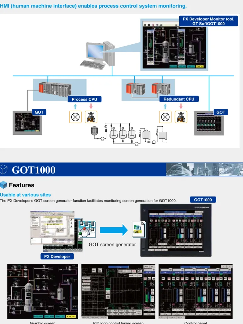
Automatically create GOT process monitoring screens
Preexisting system New system
Execute sequence control and process control simultaneously
Sequence control Process control
Simultaneous
execution
002LICLIC 001
The sequence instructions of the MELSEC-Q
series can be used without any changes.
There are over 50 types of process instructions
available for a diverse range of applications
such as cascade and feed-forward control.
Superior performance compared to DCS
Sequence control
Process control
2 degree-of-freedom
advanced PID generation FBSet point SamplePI BlendPI tuningAuto
Minimize space required for control
panel installation
User friendly operator interface
Easily monitor and operate the system
without a PC
Reduced space requirements
The compact size and modularity of Q Series allows
significant control panel space to be saved compared to
alternative systems.
Enhanced monitoring and operation capabilities
Pre-made GOT screens for alarm list, event list, and
others are available to improve monitoring and
operational capabilities.
Needs
Reduce space requirements and improve operator-friendliness
Solutions
A MELSEC controller and GOT can take the place of many loop controllers and bulky switches, indicators, etc.
There is a demand for an easy to design, modify, and maintain system that supports both loop and
sequence control. (Current system design uses separate controllers)
System scalability: expandable to other applications such as motion control and information control.
Integration of loop control and sequence control
The process CPU and redundant CPU can execute
multiple programs. Therefore, loop and sequence
control can be performed simultaneously at high speed.
Cover multiple control disciplines using a multiple CPU system
Any Q Series module can be used in a multiple CPU system, which
allows great flexibility in system design, construction, and
maintenance. Applications requiring highspeed motion control
(motion CPU), information control (PC CPU), etc. can be combined.
*Redundant CPUs do not support multiple CPU configurations.
Needs
Integrate loop control and sequence control.
Solutions
A single process CPU can execute both loop and sequence control.
Implementing a multiple CPU system is the perfect way to control other applications.
Perform loopcontrol using a programmable
controller
Process CPU:
Application Examples
System configuration
Packing
Production
Automated warehouse
Ethernet
Fine chemical manufacturing
Redundant system
Tracking cable
PC based HMI
(Monitoring)
Production
Packing
Automated warehouse
GOT GOT Redundant
system
Tracking cable
GOT GOT
MELSECNET/H Remote I/O Network Controller Network
Controller Network Controller NetworkController Network
GOT GOT
Food processing
Industrial furnace
GOT
GOT
System configuration
System configuration
Applications previously requiring separate sequence and temperature control can now be controlled using a single
process CPU. When a GOT is used in conjunction with the system, a space-saving, superior monitoring and control
solution can be created.
Mitsubishi Electric products help to provide integrated solutions for process automation and factory automation. Our
process oriented products are well suited for manufacturing chemicals, such as medicines, paint, cosmetics, and
detergent. Initial and running costs can be reduced compared to common alternatives.
Implement process control using a wide variety of high-speed sequence and loop control instructions.
Ethernet
3
Ethernet
Controller Network
Printer PC based HMI
(Monitoring)
MELSECNET/H
Remote I/O Network
Tracking cable Tracking cable
MELSECNET/H
Remote I/O Network
System configuration
Temperature sensor, flow sensor, pressure sensor, inverter, control valve, etc.
Waste incineration
Create the optimal control system to match the scale of operation.
Mitsubishi Electric process automation products are highly flexible and ready to provide the core elements
necessary for a wide range of solutions and applications.
Metering feeder
Inducted draft fan
Stack gas treatment tower
Dust collector
Air preheater fan
Incineration air blower
Stack
Dehydrated cake
Slag Incinerated ash
Drainage Water
Fuel tank
Incinerator
Melting furnace
Cyclone
Redundant
system
Redundant
system
Combustion air preheater
Smoke prevention air preheater
GOT GOT GOT GOT
GOT GOT
Redundant system
Tracking cable
Park
Discharge
Settling basin
Aeration tank
Sludge treatment facility
Advanced treatment facility
Chlorine contact tank
Water treatment
Create sophisticated systems for safe and stable water treatment using highly reliable redundant CPUs.
PC based HMI
(Monitoring)
MELSECNET/H Remote I/O Network
Water tank, coarse filter,
fine filter, water pump
Blower, tank, chlorination
Recycling sludge pump,
final sedimentation tank,
sewage pump
Filtration,
water recycling tower,
pressure pump, adjustment
Switching hub
MELSECNET/H Remote I/O Network
Redundant system
Tracking cable
MELSECNET/H Remote I/O Network
Ethernet
Redundant system
Tracking cable
MELSECNET/H Remote I/O Network
Redundant system
Tracking cable
System configuration
Controller Network
First
sedimentation tank
final
sedimentation tank
GOT GOT GOT GOT
GOT GOT GOT GOT GOT GOT GOT GOT
Controller Network
Controller Network
7
8
PC based HMI
(Information management)
MELSECNET/H
Remote I/O Network
Redundantsystem
Tracking cable
MELSECNET/H
Remote I/O Network
Redundantsystem
Tracking cable
MELSECNET/H
Remote I/O Network
Redundantsystem
Tracking cable
Ethernet
Control in building 1
Control in building 2
Control in building 3
A group control system for each building
Automated warehouse
Building 3
Building 2
Building 1
Alignment equipment
Case dispenser
Face picking crane
Palletizer
Operating sorter
Depalletizer
Material handling
Utilizing redundant systems for material handling applications ensures steady, consistent operation. The end result is a
reduction in loading/unloading delays due to control system issues.
System configuration
GOT GOT GOT GOT GOT GOT GOT GOT GOT
Semiconductor manufacturing
The dependability of purified water and gas supply systems for semiconductor applications can be increased by
implementing a redundant system. Even if one programmable controller happens to fail, the other CPU is ready to
immediately take over control and continue the operation without interruption.
Ultrapure water system
Waste gas treatment
Special gas supply
Semiconductor manufacturing plant
Wastewater treatment
System configuration
Ethernet
PC(Information level monitoring)
PC
(Monitoring and control)
Ultrapure water system
Wastewater treatment system
Gas supply, power supply, boiler, scrubber, etc.
MELSECNET/H
Remote I/O Network
MELSECNET/H
Remote I/O Network
Tracking cable Tracking cable
Controller Network
Redundant
system
Redundant
system
GOT GOT GOT GOT
Controller Network
Flow rate, pressure, concentration Temperature Sensor (i.e., limit switch) Control valve Solenoid valve Motor Pump
Reduce costs by combining FA (Factory Automation) and PA (Process Automation) in the same platform.
GOT
GOT
(Process control FBD software package)Design, debug, modify, and
monitor FBD (Function Block
Diagram) loop control programs.
PX Developer
P.31
(ActiveX® library for programmable controller communication)
Allows user programs (on the
PC) to interface with Mitsubishi
programmable controllers via
the network.
MX Component
P.40
(HMI software)
Enables a PC to function as a
graphic operation terminal using
the same screen design software
available for the GOT.
GT SoftGOT1000
P.42
Process CPU
P.15
GOT1000
P.41
(MELSEC programmable controller programming software)
The primary programming,
debugging, maintenance, and
troubleshooting engineering
tool for process and redundant
CPUs.
GX Developer
P.39
Redundant local I/O system
Process CPU
Redundant power supply system
P.21
Tracking cable
Extension cable
Extension cable
Redundant CPU
P.17
Redundant type
extension base unit
Ethernet
Tracking cable
GOT
Redundant CPU
P.17
PC for monitoring and engineering
Redundant remote I/O system
Remote I/O station
Channel isolated analog module
P.27
Loop control module
P.25
MELSECNET/H
Network System (PLC to PLC network)
Controller Network or
MELSECNET/H
MELSECNET/H
Remote I/O Network
Network System (PLC to PLC network)
CPU (process & redundant)
Modules best suited for loop control
Choose the optimum CPU based on the number of PID loops required and the scale of the application.
Choose from a wide selection of channel isolated analog modules for loop control.
Cost
High
Low
Number of PID loops
(Reference)
5
20
50
100
Q12PHCPU Q12PRHCPU
Q12PRHCPU
Q25PRHCPU
MELSEC-Q Series process CPU lineup
Other companies' loop controllers with program control
Q02PHCPU
Q06PHCPU MODE RUN ERR. USERBAT. BOOT PULL USB RS-232Great for plant
process control
Q06PHCPU
Industrial furnace etc. Plant etc. Food processing etc.
Great for process
control equipment
Q25PHCPU Q25PRHCPU BACKUP CONTROL SYSTEM A SYSTEM B TRACKING Q12PRHCPU MODERUN ERR. USER BAT. BOOT PULL USB RS-232Q02PHCPU
Q06PHCPU
Q12PHCPU
Q25PHCPU
Process CPU Redundant CPU
Process monitoring solutions
Choose a control and monitoring solution that is right for the situation.
Application
Examples
Category Application Solution Feature
GOT1000 Series
· Excellent environmental resistance · Compatible with high resolution (15" XGA) · Create process control and monitoring screens for the GOT1000 series automatically
Combination of PX Developer
Monitor tool and SoftGOT · Use GT Designer2 or GT Designer3 to create GOT screens for the PC
· Graphically represent operations on the shop floor to aid the quick understanding of system status
Commercial SCADA
· Better flexibility and range of functionality · Links to enterprise system
PC based HMI based General monitoring and control Complex monitoring and control
GOT screen generation function
SoftGOT interface
SCADA system interface
GOT screen generation function
GOT screens for monitoring, tuning, etc. can be automatically
generated from programs created using PX Developer. This
feature eliminates the time consuming tasks of assigning
devices and programming GOT screens to substantially reduce
development time. See page 37 for details.
SoftGOT interface
PX Developer monitoring functions can be 'called' or opened
directly from GT SoftGOT1000 screens. Consequently, the
development time for creating GOT screens can be reduced.
SCADA system interface
SCADA systems such as Wonderware InTouch by Invensys
Systems, Inc. can be used to create advanced graphical
displays of the system status. The PX Developer monitoring
tool is designed to interface with SCADA software and its
monitoring functions may be called and opened directly by the
SCADA software.
The company and product names above are trademarked by their respective companies.
PX Developer GT Designer2
Automatically generated
Drop-in loop control interfaces
(ActiveX control)
Easily combine alarms for monitoring
(Alarm consolidation function)
Process control data
Alarms
Select PX Developer's tags in InTouch
(Tag browser)
Directly access process control data
(DDE interface)
Alarms detected by PX Developer +
Alarms detected by InTouch
*For detailed information about each module, please refer to the appropriate user's manual. Q Series I/O modules already being used in other systems can be used with process and redundant CPUs, thereby reducing the number of required spare parts and lowering maintenance costs.
MELSEC-Q Series modules
0 1 2 3 4 5 6 7 8 9 A B C D E F 0 1 2 3 4 5 6 7 8 9 A B C D E F 0 1 2 3 4 5 6 7 8 9 A B C D E F 0 1 2 3 4 5 6 7 8 9 A B C D E F 0 1 2 3 4 5 6 7 8 9 A B C D E F 0 1 2 3 4 5 6 7 8 9 A B C D E F 0 1 2 3 4 5 6 7 8 9 A B C D E F 0 1 2 3 4 5 6 7 8 9 A B C D E F 0 1 2 3 4 5 6 7 8 9 A B C D E F Q62HLC Q62AD-DGH Q64RD-G Q64TDV-GH Q64TD Q64AD-GH Q66DA-G Q66AD-DG Q68RD3-G Q68AD-G 8CH 6CH 4CH 2CH
Current/voltage input Thermocouple RTD
0 1 2 3 4 5 6 7 8 9 A B C D E F Q62DA-FG Current/voltage output
Analog input module output moduleAnalog Loop controlmodule
Q68TD-G-H01 C o s t e ff ic ie n t High functionality
With signal conditioning function (2-wire transmitter connectable)
High resolution High resolution
Load Cell Input Module
· Just configure parameters (no programming required!) · Can continue operating regardless of CPU status (stop, error, etc.)
Q61LD
Q61LD 1CH
3
4
Process CPU
Process CPU
Product name w/ CC-Link IE w/o CC-Link IE connection
connection Q02/06PHCPU Q12/25PHCPU
GX Developer PX Developer
Version 7.20W or later Version 1.00A or later Version 8.68W or later
Version 1.18U or later
Features
· With high-speed loop processing of approximately 400
µs (2-degree-of-freedom PID), control cycles as short
as 10 ms can be achieved. Therefore, more loops can
be executed simultaneously and applications requiring
high-speed control cycles can be satisfied.
High-speed loop control
3
· When an analog or I/O module fails, it can be replaced
without stopping or turning off the CPU.
(Note 1)(GX Developer is required.)
· Output behavior (hold previous state, etc.) in the event
the CPU stops due to error can be set via parameter.
Improved reliability and maintenance features
4
· The MELSEC Process CPU features 52 instructions
dedicated for process control including a
two-degree-of-freedom PID, sample PI, auto-tuning,
and other instructions to support loop control.
Extensive loop control
2
· Create process control programs using PX Developer,
an easy-to-use FBD language engineering tool.
Simple engineering
5
· A single CPU can execute multiple programs
simultaneously, thus loop control and sequence control
programs can be processed at high-speed by the same
CPU unit.
· Process CPUs may be used in multi-CPU systems to
cover different areas of control such as high-speed
motion control (motion CPU), or information control (PC
CPU).
Integrated loop control and sequence control
1
· The process CPU is compatible with all Q Series
modules and is therefore well suited to take on a wide
variety of applications.
Compatibility and expandability
6
· From small machines to plant-wide process control, a
CPU is available to match the application.
Ample CPU lineup
7
· In combination with the high-speed, high-bandwidth
CC-Link IE controller network, operations involving
remote I/O stations and other networked controllers
benefit drastically by improved response time and
overall productivity.
Improved total system throughput
8
Software packages
Note 1) PX Developer is required to write programs using FBD.
Note 2) The processing time is the same even when using indexed devices. Note 3) Up to 124 programs can be executed.
Note 4) Indicates the total number of I/O points on the main base unit and extension base units directly controlled by the CPU module and the number of I/O points controlled as remote I/O via the remote I/O network. Note 5) Indicates the number of I/O points on the main base unit and extension base units directly controlled by the CPU module.
Note 6) Indicates the default number of points. These can be changed via parameters.
Max. 517120 points can be used by block switching in units of 32768 points (R0 to 32767) Max. 1041408 points can be used by block switching in units of 32768 points (R0 to 32767) Max. 1041408 points can be used by block switching in units of 32768 points (R0 to 32767) Max. 1042432 points can be used by block switching in units of 32768 points (R0 to 32767)
517120 points (R0 to 517119), block switching not required 1041408 points (R0 to 1041407), block switching not required 1041408 points (R0 to 1041407), block switching not required 1042432 points (R0 to 1042431), block switching not required Max. 65536 points can be used by block
switching in units of 32768 points (R0 to 32767)
Max. 131072 points can be used by block switching in units of 32768 points (R0 to 32767)
65536 points (R0 to 65535), block switching not required
131072 points (R0 to 131071), block switching not required
2048 points 2048 points 8192 points 16 points 4096 points 256 points 2048 points 2048 points 16 points 16 points 5 points Max. 4 Max. 64 Max. 7 SRAM card (1 MB)
SRAM card (2 MB) Flash card (2 MB) Flash card (4 MB) SRAM card (1 MB) SRAM card (2 MB) Flash card (2 MB) Flash card (4 MB) Standard RAM
Standard RAM Timer [T]
Retentive timer [ST] Counter [C] Data register [D] Link register [W] Annunciator [F] Edge relay [V]
File register
[R]
[ZR]
Link special relay [SB] Link special register [SW] Step relay [S]
Index register [Z] Pointer [P] Interrupt pointer [I] Special relay [SM] Special register [SD] Function input [FX] Function output [FY] Function register [FD]
Number of mountable CPU modules Number of mountable modules Number of extension base stages
(Note 6)
Input module Output module I/O composite module Analog input module Analog output module Temperature input module Temperature control module Channel isolated pulse input module
No restrictions
Version C
Product name Restrictions
Note 1) Online module change function (Function version restrictions)
Note 2) To be compatible with the CC-Link IE network module, the first five digits of the CPU module's serial number must be 10042 or later.
Sequence program control method Refresh
Ladder, list, ST, SFC Process control FBD (Note 1)
34 ns 102 ns 782 ns 400 µs 350 µs Sequence
instruction (Note 2) Process instruction (loop process time) Processing speed
Program language
Program capacity
Built-in memory
Number of steps Number of programs Standard RAM Standard ROM
Process control instructions Control cycle
Main functions
Sequence control language Process control language
LD instruction MOV instruction Floating point addition 2 degree of freedom PID Basic PID
Item
Control method I/O control mode
Internal relay [M] Latch relay [L] Link relay [B]
Number of I/O device points (Note 4) Number of I/O points (Note 5)
Specifications
Ethernet
GOT
Monitoring Station Monitoring Station Process CPUPX Developer is used together with GX Developer.
The following software versions are required for
programming the process CPU.
52
10 ms or more/control loop (setting available per loop)
2 degree of freedom PID control, cascade control, auto-tuning function, feed forward control 8192 points 4096 points 8192 points 8192 points 8192 points 2048 points 0 points 1024 points 12288 points 8192 points 2048 points 2048 points Q12PHCPU Q25PHCPU Q02PHCPU Q06PHCPU
124 k steps 124
496 k bytes
252 k steps 252 (Note 3)
1008 k bytes 28 k steps
28
112 k bytes
60 k steps 60
240 k bytes 128 k bytes
Loop control specifications
256 k bytes
or MELSECNET/H
controller network
or
MELSECNET/H
controller network
15
16
Redundant CPU
Redundant CPU, network, and power supply systems are provided to support various system configurations
specific to application requirements.
Redundant local I/O system
The CPU directly accesses I/O modules. Ideal for systems requiring high-speed response.
Approximately 50 ms
(Local I/O response time)
· Standby CPU tracking data acquisition time
· CPU switching time: Min. 32 ms (without signal flow tracking)
System switching time (Reference)
Ideal for distributed systems with multiple remote I/O stations.
Approximately 800 ms
(Remote I/O response time)
· Standby CPU tracking data acquisition time
· Output holding time of remote I/O station during control system switching: 700 to 800 ms
· CPU switching time: Min. 21 ms (signal flow without tracking)
Redundant remote I/O system
System switching time (Reference)
Monitoring Station
Monitoring
Station MonitoringStation
Switching hub
Switching hub Monitoring Station
Ethernet
Tracking cable
Extension cable
Extension cable Redundant type
extension base unit Control system CPU
Standby system CPU
Redundant power extension base unit
GOT
Tracking cable
Monitoring Station
Switching hub
Switching hub Monitoring Station Monitoring
Station
Monitoring Station
Control system CPU
Standby
system CPU
Ethernet
Remote I/O station Remote I/O station
MELSECNET/H
Remote I/O Network
GOT
GOT
or MELSECNET/H
controller network
or
MELSECNET/H
controller network
3
4
Features
Sequence instruction (Note 2)
Redundant function Process instruction (loop process time)
Tracking execution time (extended scan time) LD instruction MOV instruction Floating point addition 2 degree of freedom PID Basic PID Item Processing speed Program language Program capacity Built-in memory
Internal relay [M] Latch relay [L] Link relay [B] Timer [T]
Retentive timer [ST] Counter [C] Data register [D] Link register [W] Annunciator [F] Edge relay [V]
File register
[ZR] [R] Number of I/O device points (Note 4) Number of I/O points (Note 5) Control method
I/O control mode
Link special relay [SB] Link special register [SW] Step relay [S]
Index register [Z] Pointer [P] Interrupt pointer [I] Special relay [SM] Special register [SD] Function input [FX] Function output [FY] Function register [FD]
Number of device tracking words Number of mountable CPU modules Number of mountable modules Number of extension base stages Number of remote I/O points
Specifications
Product name Model Serial No. or Version
MELSECNET/H master module CC-Link IE Controller Network module
Redundant CPU
First five digits of the serial number are 09012 or later (when the redundant type extension base unit is used); First five digits of the serial number are 10042 or later (when the CC-Link IE Controller Network module is used)
MELSECNET/H remote I/O module
MELSECNET/H interface board
CC-Link interface module
MES interface module Web server module Ethernet interface module
Version D or later No restrictions
First five digits of the serial number are 09012 or later Note 3) Use the following serial No. or version for the redundant system.
The following functions are not available for the module mounted on the extension base unit. · Intelligent function module dedicated instructions
· Interrupt pointer
Note 2) When the redundant type extension base unit is used, I/O modules on the main base unit cannot be replaced while online.
· The basic system, including the CPU module, power
supply module, base unit, and network module, can be
configured with redundancy.
· Networks can be configured with redundancy. When
the network module fails or cable disconnection is
detected, the standby system continues control and
communications.
Basic system/network with redundancy
1
· With the redundancy of the basic system, the standby
system takes over the control to continue the system
operation when the control system fails. (Hot standby)
· By replacing the failed module or entire system, the
redundant system can be recovered quickly.
· When an I/O, analog I/O, temperature input,
temperature control, or channel isolated pulse input
module on the redundant extension base unit or remote
I/O station fails, it can be replaced without stopping or
turning off the CPU.
(Note 1, 2)(Operation on GX
Developer is required.)
· When the CPU module is replaced while the system is
operating, the parameters and programs can be copied
to the new CPU by transfer instruction from GX
Developer.
Improved reliability and maintainability
2
Loop control and sequence control in one CPU
3
· A single CPU can execute multiple programs
simultaneously, thus loop control and sequence control
programs can be processed at high-speed by the same
CPU unit.
· The Q Series modules, such as I/O, intelligent function,
and network modules, can be used without any
changes.
(Note 3)Employs existing Q Series modules
5
· In combination with the high-speed, high-bandwidth
CC-Link IE controller network, operations involving
remote I/O stations and other networked controllers
benefit drastically by improved response time and
overall productivity.
Improved total system throughput
6
· GX Developer offers simple engineering environment for
redundant system settings with the original operability.
· PX Developer facilitates creating loop control programs
using FBD language.
· Writing parameters and programs is simple using GX
Developer regardless of the system status (control/
standby).
Simple engineering
4
Redundant CPU
Software packages
PX Developer is used together with GX Developer.
The following version or later is required for programming
the redundant CPU.
Note 1) The following modules on the extension base unit or remote I/O station can be replaced while online.
Q12PRHCPU Q25PRHCPU QJ71GP21-SX QJ71GP21S-SX QJ71LP21-25 QJ71LP21S-25 QJ71LP21G QJ71BR11 QJ72LP25-25 QJ72LP25G QJ72BR15 QJ71E71-B2 QJ71E71-B5 QJ71E71-100 Q81BD-J71LP21-25 Q80BD-J71LP21-25 Q80BD-J71LP21S-25 Q80BD-J71LP21G Q80BD-J71BR11 QJ61BT11N QJ71MES96 QJ71WS96
Sequence control language Process control language
Standard RAM SRAM card (1 MB) SRAM card (2 MB) Flash card (2 MB) Flash card (4 MB) Standard RAM SRAM card (1 MB) SRAM card (2 MB) Flash card (2 MB) Flash card (4 MB) (Note 6)
Number of steps Number of programs Standard RAM Standard ROM
Process control instructions Control cycle
Main functions
Sequence program control method Refresh
Ladder, list, ST, SFC Process control FBD (Note 1)
34 ns 102 ns 782 ns 400 µs 350 µs
48 k word device memory: 10 ms 100 k word device memory: 15 ms
52
10 ms or more/control loop (setting available per loop)
2 degree of freedom PID control, cascade control, auto-tuning function, feed forward control 8192 points 4096 points 8192 points 8192 points 8192 points 2048 points 0 points 1024 points 12288 points 8192 points 2048 points 2048 points 2048 points 2048 points 8192 points 16 points 4096 points 256 points 2048 points 2048 points 16 points 16 points 5 points Max. 102400 points 1 (multiple CPU system not available)
Max. 63 Max. 7
8192 points (max. 2048 points/station)
Max. 131072 points can be used by block switching in units of 32768 points (R0 to 32767) Max. 517120 points can be used by block switching in units of 32768 points (R0 to 32767) Max. 1041408 points can be used by block switching in units of 32768 points (R0 to 32767) Max. 1041408 points can be used by block switching in units of 32768 points (R0 to 32767) Max. 1042432 points can be used by block switching in units of 32768 points (R0 to 32767)
131072 points (R0 to 131071), block switching not required 517120 points (R0 to 517119), block switching not required 1041408 points (R0 to 1041407), block switching not required 1041408 points (R0 to 1041407), block switching not required 1042432 points (R0 to 1042431), block switching not required
Note 1) PX Developer is required to write programs using FBD.
Note 2) The processing time is the same even when using indexed devices. Note 3) Up to 124 programs can be executed.
Note 4) Indicates the total number of I/O points on the main base unit and extension base units directly controlled by the CPU module and the number of I/O points controlled as remote I/O via the remote I/O network.
Note 5) Indicates the number of I/O points on the main base unit and extension base units directly controlled by the CPU module. Note 6) Indicates the default number of points. These can be changed via parameters.
Loop control specifications
Q12PRHCPU Q25PRHCPU
124 k steps 124
496 k bytes
256 k bytes
252 k steps 252 (Note 3) 1008 k bytes
First five digits of the serial number are 06052 or later (when it is mounted on the main base unit)
Product name
w/o CC-Link IE connection w/ CC-Link IE connection Redundant type extension
base unit not used Redundant type extension
base unit used
GX Developer PX Developer
Version 8.18U or later Version 1.06G or later Version 8.45X or later
Version 1.14Q or later Version 8.68W or later
Version 1.18U or later No restrictions
Version C or later
Analog output module Temperature input module Temperature control module Channel isolated pulse input module
Version C or later Input module
Output module I/O composite module Analog input module
Product name Restrictions Product name Restrictions
19
20
Redundant power supply system
The redundant power supply system can be configured to back up the system in the event of a power failure.
Redundant power supplies supporting all CPUs
1. Even if one power supply module fails, the other one supplies the power to the system.
2. A failed power supply module can be confirmed by a "power failure detection function" or "LED indicators", allowing for
quick replacement. This ensures system backup.
3. The power supply module can be replaced while online.
4. Q64RP (AC input) and Q63RP (DC input) can be used together. Creating two power supply systems (AC and DC) further
enhances system reliability.
External power supply prevents the system from being affected by a power failure
Even if a power failure occurs at more than two stations in a loop system, a station in between can continue data link. This
function also prevents loopback in the system. The link scan time can be stabilized, ensuring steady system operation.
The external power supply function enables the system to continue data link when the power supply module fails.
Fiber optic loop network module
with external power supply function
Specifications
Item
Q38RB, Q68RB, Q65WRB
8.5 A 9.35 A or more
5.5 to 6.5 V 65% or more
ERR contact 24 V DC/0.5 A
5 V DC, 1 mA
OFF to ON: 10 ms or less, ON to OFF: 12 ms or less Mechanical: 20,000,000 times or more
Electrical: 100,000 times or more at rated switching voltage and current No
No Applicable base unit
Input power supply
Input frequency Input voltage distortion rate Maximum input apparent power Maximum input power Inrush current Rated output current Overcurrent protection Overvoltage protection Efficiency
Allowable momentary power failure period Application
Rated switching voltage/current Minimum switching load Response time
Life
Surge suppressor Fuse
Contact output
Q64RP
24 V DC (+30%, -35%) (15.6 to 31.2 V DC)
N/A N/A N/A 65 W 150 A, 1 ms or less
10 ms or less (at 24 V DC input) 100 to 120 V AC/200 to 240 V AC (+10%, -15%)
(85 to 132 V AC/170 to 264 V AC) 50/60 Hz ±5%
Within 5% 160 VA
N/A 20 A, 8 ms or less
20 ms or less
Q63RP
Specifications
Features
Features
Q64RP
or
Q63RP
Q64RP
or
Q63RP
Power supply slot 1*
* Either Q64RP or Q63RP can be mounted on the power supply slot 1 and 2.
Also, in the event of a power failure, the power supply module can be replaced while online.
Power supply slot 2*
Item Controller Network module
QJ71GP21S-SX
MELSECNET/H network module QJ71LP21S-25
0.28A 0.20A
External power supply
20.4 to 31.2 V DC
M3 R1.25-3 0.3 to 1.25 mm2 0.42 to 0.58 N·m 1 ms (Level PS1)
By noise simulator of 500Vp-p noise voltage, 1µs pulse width, and 25 to 60Hz noise frequency Voltage
Current Terminal screw size Applicable solderless terminal Applicable wire size Tightening torque
Allowable momentary power failure time Noise immunity
Control station (Station 1) Normal station (Station 2) Normal station (Station 3)
Control station (Station 6) Normal station (Station 5) Normal station (Station 4)
24 V
Not disconnected from network
With external power supply function
Control station (Station 1) Normal station (Station 2) Normal station (Station 3)
Control station (Station 6) Normal station (Station 5) Normal station (Station 4)
Loopback
Loopback
Disconnected because it is located between two failed stations.
Normal but disconnected
Without external power supply function
Power failure
Power failure
Power failure Power failure
External power supply
24 V
External power supply
24 V
External power supply
24 V
External power supply
24 V
External power supply
24 V
External power supply
When a power failure occurred in two stations:
Controller Network or
MELSECNET/H
Network System (PLC to PLC network)
Controller Network or
MELSECNET/H
Network System (PLC to PLC network)
4
Multiplexed remote I/O network system
Redundant system with superior cost effectiveness by using highly reliable, high-speed network.
Facilitating the multiplexed remote master station and multiplexed remote sub-master station on one remote I/O network
system enables the multiplexed remote sub-master station to control the remote I/O network system instead when the
programmable controller CPU in the multiplexed remote master station becomes faulty.
The multiplexed remote master station can return to normal and to system operation as a multiplexed remote sub-master
station, even during the remote I/O network system control by the multiplexed remote sub-master station, thus preparing
itself for a multiplexed remote sub-master station.
The CC-Link Master station duplex function enables the data link to continue working by switching the control to the standby
master station (meaning a backup station for the master station) automatically if system down occurs in the master station due
to a malfunction in the programmable controller CPU or power supply.
The master station can return to normal and to system operation as the standby master station, even during data-link control by
the standby master station, thus preparing itself for the standby master station system down.
Cost-saving redundant system by using open field network.
CC-Link Master station duplex function
Features
Features
�
Usable CPU is Process CPU (QnPHCPU).
�
The redundant system configured with QnPHCPU + MELSECNET/H (remote I/O network).
(Note 1)�
The multiplexed remote function enables the multiplexed remote sub-master station to continue the I/O working when the
multiplexed remote master station becomes faulty due to a malfunction in power supply, etc.
�
The redundant system can be configured in CC-Link network regardless of the CPU types of the master station, standby
master station.
(Note 2)�
The CC-Link Master station duplex function enables the standby master station to continue the data link working when the
master station becomes faulty. The master station can return to normal and to system operation as the standby master
station, even during data-link control by the standby master station.
System configuration
System configuration
Multiplexed sub-master station
Remote I/O station
Remote I/O station Multiplexed
master station
Switches the master function
Continues the data link
Remote I/O station Remote I/O station Remote I/O station
Ethernet
Ethernet
MELSECNET/H (Remote I/O network)
Monitoring station Monitoring station
MELSECNET/H remote master
MELSECNET/H remote sub-master
QnPHCPU QnPHCPU
700 to 800ms
(when connecting 4 remote I/O stations)
· Changed by sequence scan time, link scan time.
System switching time (reference time)
220 to 1500ms
· Changed by baud rate of CC-Link, sequence scan time,
link scan time.
System switching time (reference time)
Master station
Standby master station
Data server Monitoring server
Standby
master station I/O station I/O station Master station
Switches the master function
Continues the data link
(Note 1) When tracking is needed, the communication module (Ethernet, etc.) to communicate the tracking data and the creation of the user program for tracking is required. Note 2) When tracking is needed, the communication module (Ethernet, etc.) to communicate the tracking data and the creation of the user program for tracking is required.
23
24
Loop control module
Ideal for fast response control such as
Features
Specifications
High-speed PID control
1
The Q62HLC loop control module performs a continuous
PID control and supports thermocouple inputs,
microvoltage inputs, voltage inputs, current inputs, and
current outputs. These features make the Q62HLC ideal
for fast response control.
Program control function
4
Control program profiles can be specified where set
values (SV) and PID constants (Proportional band,
Integral time, Derivative time) are automatically changed
at specified times.
Cascade control function
5
Cascade control can be performed with channel 1 as the
master and channel 2 as the slave.
Connectable to thermocouples complying with
major international standards
2
Thermocouples complying with the JIS, IEC, NBS, and
ASTM standards are supported.
Supports a variety of input ranges
3
The use of an input sensor (microvoltage, voltage, and
current inputs) enables analog value measurements in
the ranges shown below.
M Thermocouple Tank Heater Control output Control output Temperature input
Flow rate sensor Flow rate sensor input
Q62HLC Thyristor
· Rapid temperature increase control in flip chip bond IC manufacturing
· Drying oven cooling temperature control on freeze drying machines
JIS Standard
R, K, J, S, B, E, T
IEC Standard
R, K, J, S, B, E, T, N
NBS Standard
PL
ASTM Standard
W5Re, W26Re
Items complying with any of these can be used
Resin nozzle temperature control
Microvoltage
0 to 10 mV 0 to 100 mV -10 to 10 mV -100 to 100 mV
Voltage
0 to 1 V 1 to 5 V 0 to 5 V -1 to 1 V -5 to 5 V -10 to 10 V
Current
4 to 20 mA 0 to 20 mA
Q62HLC
SV Program control using 16-segment program profile Time Control output Master (CH1) Slave (CH2) Thermocouple Heater Thermocouple Extruder
CH1
CH2
Number of analog I/O points
Number of input points
Specifications Item
2 channels/module
Analog input specifications Analog output specifications
2 points (2 channels) Number of output points 2 points (2 channels)
Analog input See (2)
K, J, T, S, R, N, E, B, PL II, W5Re/W26Re
Digital input 16-bit signed binary
Digital output 16-bit signed binary Analog output Current
Usable thermocouples – –
Input characteristics See (1) Output characteristics
Maximum resolution See (1)
See (2) (a) See (2) (b)
Maximum resolution 4 µA
Ambient temperature: 23°C ± 2°C Indication accuracy
Cold junction temperature compensation accuracy
Full scale x (±0.2%)
Ambient temperature: 0°C to 55°C Full scale x (±0.4%)
Ambient temperature: 23°C ± 2°C ±0.5°C
– –
Ambient temperature: 0°C to 55°C ±1.0°C
Conversion speed (constant regardless of the number of channels used)25 ms/2channels Conversion speed (constant regardless of the number of channels used)25 ms/2channels
25 ms/2channels
(constant regardless of the number of channels used)
Sampling period (constant regardless of the number of channels used)25 ms/2channels Control update time
Absolute maximum input Microvoltage: ± 12 V, voltage: ± 15 V, current: ± 30 mA Allowable load resistance 600 Ω or less Input impedance Thermocouple, microvoltage, voltage: 1 MΩ, current: 250 Ω Output impedance 5 MΩ
Ambient temperature: 23°C ± 2°C Output
accuracy Ambient temperature: 0°C to 55°C
Digital input value: 0 to 1000 (0 to 4000 when using simplified analog output)
Output range: 4 to 20 mA
Note 2) Accuracy is calculated as follows: [Accuracy] = [Indication accuracy] + [Cold junction temperature compensation accuracy]
Thyristor
(1) Usable input sensor types, measurement ranges, and data resolution
(2) Indication accuracy
(a) At ambient temperature of 23
±
2°C
(b) At ambient temperature of 0 to 55°C
K
T
Input range Input
-200 to 400°C
J -200 to 1200°C
-200 to 1372°C
S -50 to 1768°C
R -50 to 1768°C
N
W5Re/W26Re 0 to 2300°C Thermocouple
0 to 10 mV
Microvoltage
-1 to 1 V Voltage
-5 to 5 V -10 to 10 V
Current 4 to 20 mA
0 to 20 mA 0 to 1 V 1 to 5 V 0 to 5 V 0 to 100 mV -10 to 10 mV -100 to 100 mV
0 to 10 V
E -200 to 1000°C
B PL II
0 to 1800°C 0 to 1300°C
0 to 1390°C
Digital value Resolution
-2000 to 4000 -2000 to 12000 -2000 to 13720
-500 to 17680
-500 to 17680 0.1°C
0 to 23000
0 to 20000
-10000 to 10000
0 to 20000 0 to 20000 -10000 to 10000
-2000 to 10000 0 to 18000 0 to 13000
0 to 13900
0.5 µV 5 µV 1 µV 10 µV 0.05 mV 0.2 mV 0.25 mV 0.5 mV 0.1 mV 0.5 mV 1 mV 0.8 µA
1 µA
Error
Item
500°C or more -100 to less than 500°C
Less than -100°C
S, R, N, W5Re/W26Re K, J, T, E, PL II
-50 to less than 1000°C 1000°C or more
Voltage Full scale x (±0.1%)
Thermocouple
B 400 to less than 1000°C 1000°C or more Less than 400°C
Microvoltage
Current
± [Indication value x (0.1%) + 1 digit]
± 0.5°C
± 1.0°C
± 1.0°C
± [Indication value x (0.1%) + 1 digit]
± 1.0°C
± [Indication value x (0.1%) + 1 digit]
± 70.0°C
Error
Item
500°C or more -100 to less than 500°C
Less than -100°C
S, R, N, W5Re/W26Re
-50 to less than 1000°C 1000°C or more
Voltage Full scale x (±0.2%)
Thermocouple
B 400 to less than 1000°C 1000°C or more Less than 400°C
Microvoltage
Current
± [Indication value x (0.2%) + 1 digit]
± 1.0°C
± 2.0°C
± 2.0°C
± [Indication value x (0.2%) + 1 digit]
± 2.0°C
± [Indication value x (0.2%) + 1 digit]
± 140.0°C
Staggering 25 ms sampling and control update time,
industry's fastest.
Supports sensor types, such as thermocouple,
microvoltage, and current input ranges.
Continuous PID control by 4 to 20 mA current output
results in highly stable and accurate control.
K, J, T, E, PL II
Segment 16 Segment 15 Segment 3 Segment 2 Segment 1 Set v alue (SV1) Execution time
PID constants Program pro
file
Accuracy
(Note 2)
Channel isolated analog modules
Item
Isolation method
No. of occupied I/O points External connections
32-bit Analog input
±71.4 ppm/°C (0.00714%/°C)
16 points (I/O assignment: Intelligent 16 points) 18-point terminal block
0 to 64000 0 to 5 V DC, 1 to 5 V DC, 0 to 10 V DC;
0 to 20 mA DC, 4 to 20 mA DC -64000 to 64000 (-10 to 10 V DC)
0 to 32000 0 to 5 V DC, 1 to 5 V DC, 0 to 10 V DC;
0 to 20 mA DC, 4 to 20 mA DC -32000 to 32000 (-10 to 10 V DC)
Q64AD-GH Temperature coefficient Reference accuracy 16-bit
Between I/O terminal and programmable controller power supply: Photocoupler Between analog input channels: Transformer
±0.05%
Digital output value (32-bit): ±32 digits Digital output value (16-bit): ±16 digits
Channel isolated high resolution analog
input module
Channel isolated analog input module
8 points (8 channels)
0 to 5 V DC, 1 to 5 V DC, 0 to 10 V DC, -10 to 10 V DC, user range
±15 V, ±30 mA
±0.1%
High resolution mode (0 to 10 V, -10 to 10 V): ±16 digits High resolution mode
(other than the above ranges): ±12 digits Normal resolution mode: ±4 digits
No. of occupied I/O points External connections
32-bit Check terminals
16 points (I/O assignment: Intelligent 16 points) 18-point terminal block
0 to 64000 0 to 32000
Yes
16-bit
Between I/O terminal and programmable controller power supply: Photocoupler Between analog input channels: Transformer
Between external power supply and analog input channel: Transformer
Channel isolated high resolution analog
input module
(with signal conditioning function)
Channel isolated analog input module
(with signal conditioning function)
Accuracy (accuracy to max. digital output value) High resolution mode Normal resolution mode Check terminals
±71.4 ppm/°C (0.00714%/°C) 10 ms/channel
Transformer
16 points (I/O assignment: Intelligent 16 points) 40-pin connector
Digital output
0 to 12000
0 to 4000 Yes Temperature coefficient Reference accuracy Sampling cycle Isolation method No. of occupied I/O points External connections
±0.1%
High resolution mode: ±12 digits Normal resolution mode: ±4 digits
High dielectric withstand voltage
A wide selection of channel isolated analog modules are provided to meet requirements for process control and
high-accuracy control.
External signal converters are not required.
Electric disturbances such as current and noise can be isolated.
Standard analog input module Channel isolated analog module
Isolated with a transformer
Warning and error detection functions
Analog modules monitor analog input signals and notify
warnings and errors.
Upper upper limit
Upper lower limit Value of CH 1
Warning cleared
Warning cleared Warning cleared
Time Digital output value
Warning occurred Warning occurred
Warning occurred
Warning output range
Value of CH 2 Lower upper limit
Lower lower limit
Outside of warning output range
Specifications
Features
Disconnection detection function
When the analog output range is 4 to 20 mA or the user range
setting of current, disconnection is detected by monitoring output
values.
Cost and space requirement reduction (multi-channel type)
Online module change (hot swap)
Even if the analog module fails during operation, it can be
replaced without stopping the system.
Scaling function
(Q68AD-G, Q66AD-DG, Q66DA-G, Q68TD-G-H02)
A value input from an external device can be converted to an
arbitrary value. This function eliminates the need for a ladder
program that converts A/D conversion data to an actual physical
value.
Control panel
Signal converters
Sensor 2-wire transmitter
Without channel isolated analog module
Sensor 2-wire transmitter
With channel isolated analog module
Control panel
Warning occurred
No. of analog input points 4 points (4 channels)
Absolute max. input ±15 V, ±30 mA
Current 0 to 20 mA DC, 4 to 20 mA DC, user range Voltage 0 to 5 V DC, 1 to 5 V DC, 0 to 10 V DC,-10 to 10 V DC, user range
Item Q62AD-DGH
10 ms/4 channels Conversion speed
±0.05%
Digital output value (32-bit): ±32 digits Digital output value (16-bit): ±16 digits Reference
accuracy
±71.4 ppm/°C (0.00714%/°C) Temperature
coefficient
10 ms/2 channels Conversion speed
Q66AD-DG
Item Q68AD-G Item
0 to 20 mA DC, 4 to 20 mA DC, user range
0 to 16000 (0 to 10 V DC),
0 to 12000 (0 to 5 V DC, 1 to 5 V DC; 0 to 20 mA DC, 4 to 20 mA DC), -16000 to 16000 (-10 to 10 V DC),
-12000 to 12000 (user range) 0 to 4000 (0 to 10 V DC, 0 to 5 V DC, 1 to 5 V DC;
0 to 20 mA DC, 4 to 20 mA DC) -4000 to 4000 (-10 to 10 V DC, user range)
±71.4 ppm/°C (0.00714%/°C) 10 ms/channel
Transformer
16 points (I/O assignment: Intelligent 16 points) 40-pin connector
Isolation method
Input specifications
Power supply specifications
No. of analog input points
Reference accuracy No. of analog input points
Absolute max. input Voltage Current High resolution mode Normal resolution mode Temperature coefficient Sampling cycle Isolation method No. of occupied I/O points External connections Accuracy (accuracy to max. digital output value) Digital output Analog input
26±2 V DC Supply voltage
24 mA DC Max. supply current
Yes (limit current: 25 to 35 mA) Short-circuit protection
6 points (6 channels)
2-wire transmitter connection
Input specifications
Power supply specifications
4 to 20 mA DC (input resistance: 250 Ω), user range
(0 to 20 mA DC without 2-wire transmitter) No. of analog input points
(no. of 2-wire transmitters)
Analog input Accuracy
(accuracy to max. digital output value)
Accuracy (accuracy to max. digital output value) Digital output Digital output
2 points (2 channels)
Analog input
2-wire transmitter connection
Supply voltage
Max. supply current
Short-circuit protection
26±2 V DC
24 mA DC
Yes (limit current: 25 to 35 mA) 4 to 20 mA DC (input resistance: 250 Ω),
user range
With multi-channel modules, more cost effective and small
footprint systems can be configured.
Control
panel
Control
panel
Reduced
wiring, cost,
and space
requirements
Input range setting: 0 to 20 mA, 4 to 20 mA (Q68AD-G, Q66AD-DG)
0 4 20
Analog input Current (mA) Scaling lower limit
Scaling upper limit Analog output value (Scaling value)
Input range setting: -10 to 10 V (Q68AD-G)
-10 0 10
Analog input Voltage (V) Scaling lower limit
Scaling upper limit Analog output value (Scaling value)
GX Developer
System in operation
Replace the module Perform "Online
module change."