Compatibility of Reduced Activation
Ferritic/Martensitic Steel with Liquid Lithium
Xu, Qi
Doctor of Philosophy
Department of Fusion Science
School of Physical Sciences
The Graduate University for Advanced Studies
2008
.
Abstract
Development of breeding and structural materials for blankets is the key issue of fusion reactors. Fe-Cr-W based RAFM (Reduced Activation Ferritic/Martensite) steels are widely regarded as promising blanket structural materials, because of its low activation properties, radiation resistance and industrial maturity. Blanket concepts with liquid lithium (Li) breeder/coolant provide attractive options for high tritium breeding ratio, high efficiency and simplicity of blanket system.
One of the critical issues for RAFM/Li blanket is the compatibility of RAFM steel with liquid Li. As to the corrosion of ferritic steels in Li, only studies on conventional Fe-Cr-Mo are available. In those studies, however, investigation on microstructure and micro-chemical processes are quite limited. Any data are not available for RAFM (Fe-Cr-W) steels yet.
The purpose of the present study is to examine the compatibility of RAFM steels with liquid Li with respect to corrosion rate and the degradation of mechanical properties and to classify the underlying mechanism based on the element transfer and change of microstructure during the corrosion process.
In this study, the compatibility of JLF-1(Fe-9Cr-2W-0.1C), a RAFM steel developed in Japan, with static and flowing Li was investigated. The coupon specimens (16×4×0.25mm) were exposed in an isothermal pot for static tests and thermal convection SS316 (Fe-Cr-Ni) loop for flowing tests. After exposure, the corrosion characteristics were examined by fine scale weight measurement, SEM/EDS (Scanning Electron Microscope/Energy Dispersive X-ray Spectrometer), TEM (Transmission Electron Microscopy) and Vickers hardness test.
In the static test, the weight loss of JLF-1 specimens increased with temperature. After exposure at 700ºC for 100h, JLF-1 specimens suffered severe corrosion and the corrosion rate was 0.18mm/yr. The kinetics of weight loss at temperature of 500ºC and 600 ºC showed that the corrosion of JLF-1 became saturated with the exposure time. This is possibly due to the formation of saturated layer of dissolved elements in liquid
lithium near the specimen surface. In the corrosion test in a thermal convection loop, the corrosion rate at 500ºC for 250h was significantly larger than that obtained in the static test in an identical condition. After Li exposure, the phase transformation from martensite to ferrite was found on the samples. This is the first time that the phase change from martensite to ferrite is observed after Li attack. The chemical analysis results and the depletion of carbides suggested that the phase change should be caused by the depletion of carbon. At the same time, selective depletion of other alloy elements, such as Cr and W, was detected by EDS on the surface. Vickers hardness results showed that obvious softening occurred on the surface of the specimens after Li exposure and the depth of the softened region was consistent with that of the phase transformation. The flowing Li enhanced the weight loss, phase change and reduction of hardness due to the mass transfer effect.
The influence of alloy composition on the corrosion was investigated by comparing the corrosion behavior of JLF-1, binary Fe-Cr and pure iron at 700°C for 100hr. The corrosion of JLF-1 is more significant than that of Fe-9Cr and pure iron at 973K. The selective dissolution of Cr, W and C into lithium seems to enhance the corrosion. Significant phase transformation from martensite to ferrite to the depth of 100μm was observed on the JLF-1 specimens after exposure in Li at 700°C for 100h. The phase change resulted in drastic hardness drop from 250 to 140Hv. For the Fe-9Cr, the softened layer (~5μm) was found on the surface of the specimen after Li attack due to the depletion of Cr and W. This was verified by the EDS line scan on the cross section of specimens. No mechanical change was observed on the pure Fe specimen before and after exposure.
To study the influence of container materials, the coupon specimens of JLF-1 were exposed in Mo, SS316 and Nb crucibles separately at 600°C for 250h. The corrosion characteristics in different crucible were compared. After exposure, the specimens exposed in Mo and Nb crucible lost weight, while the specimens in SS316 crucible gained weight due to the precipitation of Ni dissolved from crucible materials. The
crucible (~20μm) and Mo crucible (~10μm). No phase change was found in the case of SS316 container. The phase change caused a corresponding reduction of hardness on JLF-1 samples in depth. It is clear that the Nb container enhanced the depletion of carbon and the phase transformation by trapping C and achieving a very low C concentration in Li.
Analysis of the experimental results was carried out based on the thermodynamic and kinetic modeling. The results showed that the driving force of corrosion is the level of Fe and Cr in Li. Saturation of those elements in Li results in the suppression of corrosion. However, production of compounds of N, Li and alloy elements was shown to determine the level of Fe and Cr in Li. The loss of C leads to the phase change. The driving force of decarburization is the level of C in Li. The trapping of C by the container materials can enhance the phase transformation. The diffusion of C in the martensite controls the extension of phase change region.
In conclusion, expected influences of Li attack to RAFM steel are the loss of materials by dissolution of the constituent elements and the degradation of mechanical properties caused by phase transformation from martensite to ferrite as the result of dissolution of C. Based on the data obtained, the compatibility of RAFM steel in Li seems not to be a serious issue once the level of N in Li is kept low. The phase transformation will be reduced by avoiding the use of materials which has high affinity with C.
CONTENTS
CHAPTER 1. Introduction ……….… 1
1.1 Fusion reactors and blanket systems ……….. 2
1.2 Candidate structural materials for blanket ……… 10
1.3 The concept of Li/RAFM steel blanket and compatibility issue ……….. 15
1.4 Research status of the compatibility of structure materials in Li ………. 19
1.5 Objectives of the present study ………. 26
CHAPTER 2. Experiment ………. 27
2.1 The composition and pretreatment of specimens ……….. 28
2.2 Specimen preparation and experiment system ……….. 29
CHAPTER 3. Comparison of corrosion behavior of JLF-1, pure Fe and Fe-9Cr in static liquid Li ………. 35
3.1 Experimental condition ……….. 36
3.2 Results and discussion ………... 37
3.3 Summary ……….... 43
CHAPTER 4. The compatibility of JLF-1 in static and flowing Li………... 45
4.1 Experimental parameters ………... 46
4.2 The corrosion characteristics in static and flowing condition ………... 49
4.3 Discussion ……….. 56
4.4 Summary ……… 58
CHAPTER 5. The effect of container materials on the corrosion behavior in Mo, Nb and SUS316L container ………. 59
5.1 The experiment in different containers ……….. 60
5.2 The investigation on container effect ……….... 61
5.3 The role of container materials in decarburization ……… 66
5.4 Summary ……….... 68
CHAPTER 6. Discussion and modeling of corrosion behavior of JLF-1 in Li ……... 71
6.1 Effect of N on corrosion ………... 72
6.2 Dissolution of Mo ……….. 78
6.3 Depletion of C and phase change ……….. 84
6.4 Behavior of Ni in corrosion system ………... 92
6.5 Summary ……… 94
CHAPTER 7. Comparison to previous data ……….. 95
CHAPTER 8. Conclusion ……….. 99
REFERENCES ……… 101
LIST OF PAPERS AND PRESENTATIONS ……… 105
ACKNOWLEDGEMENTS ……… 107
Chapter 1
Introduction
1.1 Fusion reactor and blanket system
1.1.1 The energy crisis and fusion
Energy is essential in modern society. It was used everywhere, lighting, heating transport, industry and agriculture. At present, around 80% energy is produced by burning the fossil fuels, some come from the nuclear fission, and a few amount come from the renewable energy source, such as hydro, solar and wind.[1]
Following the growth of the world’s population and the rising of living standards in many developing countries, the worldwide energy demand will increase in the coming decades. However, the burning of the fossil fuel releases CO2, which is pointed out to result in global warming and climate change. The nuclear fission faces the problem of the radioactive waste with long half time. The development of renewable resources cannot meet the demand of energy. Furthermore supplement of fossil fuels is limited. It was predicted by Donald L. Klass [2] that oil reserves will be used up within 20-70 years at an annual growth rate of 2.3% in consumption and 30-70 years for the natural gas at an annual growth rate of 3.2%.
The depletion of worldwide resources will inevitably lead the political instability and conflict. The global warming caused by emission of green house gases could lead to environmental disaster. Sustained development of human being requires a safe and long term energy resource. The controlled fusion seems to be a promising answer to these demands. [3-5] The advantages of the fusion reactor include:
• The basic fuels (deuterium and tritium) are abundant everywhere;
• No greenhouse gas emissions;
• Day-to-day operation of a fusion power station does not require the transport of radioactive materials;
• Fusion power stations can be made inherently safe. "Runaway" or "meltdown" accidents are impossible; and
1.1.2 Fusion reaction
Nuclear fusion is a process where two or more nuclei combine to form an element with a higher atomic number (more protons in the nucleus). Fig.1.1-1 shows the reaction between deuterium and tritium. Fusion of light elements (the reactants) into heavier elements (the products) releases energy, (as does fission of heavy elements into lighter elements). For fusion, the energy release occurs when the total mass of the fusion products is smaller than the reactants. The difference between the total masses of all the protons and neutrons of a nucleus and the mass of the nucleus itself can be expressed in terms of the binding energy. The energy released is proportional to the difference in the masses as predicted by Einstein's famous equation,
E=mc2. (1.1-1)
where E is energy, m is mass and c is the speed of light (3×10⁸m/ sec. ).
Fig.1.1-1 The D-T fusion reaction, is the most efficient reaction known in terms of energy released (from ITER homepage)
There are many kinds of fusion reactions, practical ones for energy nowadays are shown in Fig. 1.1-2.[6] The figure indicates that the most effective reaction occurs between deuterium (D) and tritium (T), at the lowest ignition temperature, because D-T
reaction has the largest fusion cross-section among the reactions.
Fig. 1.1-2 Different fusion reactions require different temperatures and have different energy yields
To achieve a fusion reaction, it is necessary to bring the reactants so close together that nuclear forces become important and "glue" the reactants together. But, the distance of interaction of the nuclear force is very small (10-15 meters), and the reactants (positively charged nuclei) repel each other because of the electrostatic force. For these reasons fusion most easily occurs in a high density, and high temperature environment.
On Earth, nuclear fusion was reached first in the explosion of the Hydrogen bomb. In a non-destructive manner, fusion has also been reached in different experimental devices aimed at studying the possibility of producing energy in a controlled fashion. The D-T reaction is presently the best candidate for implementing a controlled fusion power station in the near future.
There are several experiments worldwide where the conditions for nuclear fusion reactions have been achieved in a controlled manner. The two main methods are being explored are Magnetic Confinement Fusion (MCF) and Inertial Confinement Fusion (ICF). [7]
1) In MCF, a (Deuterium-Tritium) plasma is kept confined (typically within a doughnut shaped container) by a strong magnetic field and heated up to temperatures where the fusion reactions start to occur at a significant rate. 2) In ICF, high-energy lasers impact and compress a solid (frozen)
Deuterium-Tritium pellet producing an implosion that eventually raises the temperature of the pellet (that has become plasma) enough to trigger nuclear fusion reactions.
These two methods are quiet different in the standpoint of physics or engineering. Here only the research works on MCF are introduced.
1.1.3 Fusion reactor
To realize the MCF, several devices were developed, such as Tokamak, Stellarator and Magnetic Mirror etc. In a Tokamak device, the magnetic field confines the plasma within a torus vessel and keeps the high-temperature plasma away from the vessel wall. The research on Tokamak principle have been performed widely and got many achievements, such as TFTR in the U.S [8,9], JET in Europe [10] and JT-60U in Japan [11], et al. Now a great effort is being made on a Tokamak type International Thermonuclear Experimental Reactor (ITER).[12,13] Fig. 1.1-3 shows the cutaway of ITER.
The function of parts or system in ITER is:
1) First wall
First wall directly faces the plasma and protect other components, such as blanket and vacuum system. It suffers from the high flux of heat and neutron. Because the impurities produced by sputtering of plasma poison the plasma, the choice of first wall materials is still a concern. The candidates for first wall are low Z materials C and high Z materials W.
Fig. 1.1-3 ITER Tokamak cutaway (from ITER homepage)
2) Divertor
The function of divertor is to remove the impurities and fusion product helium. These particles are guided by the magnetic field to divertor. After neutralization, the fusion wastes are derived out by pump. Considering the high heat flux, the W may be the most promising candidate materials for divertor. The concepts of liquid metal divertor were proposed [14], but it still faces some technical problems.
3) Vacuum vessel
Vacuum vessel provides high vacuum boundary for the plasma and the first line of confinement against radioactive release within the vessel. Very high vacuum is achieved to prevent the impact of plasma. At the same time, vacuum system should be strong enough to support the first wall, blanket and divertor inside.
4) Superconducting magnet systems,
Superconducting magnet system include the toroidal field (TF) coil, poloidal field (PF) coil and central solenoid (CS) coil, produce a strong magnetic field to confine the
Toroidal Field Coil
Poloidal Field Coil
Blanket Module
(Li, Li-lead, Flibe)
Vacuum Vessel
material is Nb3Sn. [15]
5) Cryostat
The Cryostat is used to ultra-low temperature to superconducting magnet.
6) Blanket
In real fusion reactor, the 80% heat is released by neutron after the D-T reaction. The blanket transforms the neutron energy to heat and transports the heat to the outside. Furthermore, the fuel to fusion reaction, tritium, is produced in blanket. To achieve the above purposes, the blanket consists in breeder, coolant, neutron multiplier. The structure materials of blanket are the main concern of this work. It will be discussed in detail later. ITER will have only “shield blanket”. DEMO blanket concept will be tested in ITER as ITER Test Blanket Module (TBM).
The ultimate goals of ITER are to demonstrate ignition and extended burns of D-T plasmas with steady-state and serve as a test facility for advanced components such as blankets [16]. ITER is just an experimental reactor with the fusion power of 0.5-0.7GW. The power is much lower than the fusion reactor (3-4GW) in the future [17]. Also the lower neutron wall load in ITER has much lower fusion power and neutron wall load. This allows the application of traditional steels, such as SS316 as structural materials. In the future, the neutron wall load would be high up to 3 MW/m2,[17] and hence advanced structural materials should be used.
1.1.4 Blanket system
The blanket is located between the plasma and vacuum vessel and provides the main thermal and nuclear shielding to the vessel and other components. The blanket also works as tritium producer and thermal generator in the fusion reactor. To realize these goals, many different concepts were proposed. All of the DEMO concepts could be classified with regard to the breeding materials into two categories [18-23]: solid
ceramic and liquid breeders with the options of self-cooled or separately cooled versions. These concepts also depend on development of structure materials and the design parameters, such as thermal exchange ratio, neutron flux and Tritium Breeding Ratio (TBR). The main functions of blanket are:
(1) The recycle of tritium
As mentioned before, the D-T reaction is the most effective fusion reaction. There is abundant deuterium on earth. The concentration of deuterium in sea water is around 160ppm. However the natural tritium does not exist. The economical way of tritium production is to generate tritium during the operation of fusion reactor bases on the following equations:[24]
3 - 1.1 2.47MeV -
n T He n
Li
2 - 1.1 78MeV .
4 T He n
Li
7 4 6 4
+ +
⎯→
⎯ +
+ +
⎯→
⎯ +
Figure 1.1-4 the cross section of 6Li and 7Li [25]
The percentage of Li isotopic, 6Li and 7Li is 7.42% and 92.58% on earth
reaction of 1.1-2 dominates tritium production in most case, according to the Fig. 1.1-4. On the other hand, the space for blanket is so small in fusion reactor, that the neutron absorbed by Li is limited. So the neutron multiplier is necessary in some blanket designs. Usually the beryllium (Be) or lead (Pb) is involved to achieve the purpose:
5 - 1.1 7MeV -
Pb 2n
n Pb
4 - 1.1 2.5MeV -
He 2 2n n
Be
1 - A A
4 9
+
⎯→
⎯ +
+
⎯→
⎯ +
Another concern related to the recycle of tritium is how to transport and extract tritium generated in the blanket. Nowadays the most promising method is to bring the tritium out using flow of the coolant or by arranging a separate gas flow for purging, then extract the tritium outside the reactor. The inventory of tritium in coolant and the penetration of tritium should be evaluated before this method is selected.
(2) The neutron shield
Another important function of blanket is to slow down the neutrons and protect the vessel and other components, especially the magnet. The irradiation with neutrons heats up the coil of magnet and results in the failure of superconductivity. Long time irradiation also leads to the degradation of superconductivity and reduces the life time of structural and insulating materials in the blanket system.
(3) The generation and transport of heat
The irradiation of neutron heats up the blanket system. To protect the blanket and transform the energy to electricity, the coolant is involved in the blanket. The potential candidates of coolant are helium, water or liquid metal, etc. The choice of coolant depends on the energy exchange efficiency and the concept of blanket design.
1.2 Candidate materials for blanket
1.2.1 Structural materials
It has been recognized that the development of blanket structural components is the key issue to the successful attainment of safety, environmental and economical advantages of fusion power system. It is essential that the materials satisfy requirements on basic physical and chemical properties which allow a reactor design with high power density, high power conversion efficiency, high availability and attractive safety and environmental attributes. [26]
1.2.1.1 The requirement for structure materials
The structural materials of first wall and blanket in D-T tokamak reactor suffer from:
· High surface heat flux causes mechanical and electromagnetic loading and alternating thermal stresses.
· High energy (14.1 MeV) fusion neutrons produce displaced atoms and helium, hydrogen, and solid transmutation products, leading to changes in bulk properties.
The blanket systems are large systems with combined thermal, hydraulic and mechanical loading, irradiation, corrosion etc. The requirements for fusion structural materials are [27]:
1) The material could withstand high neutron wall loads under temperatures and coolant pressure conditions necessary to drive efficient thermodynamic cycles in a blanket;
2) The lifetime of structural material must be long enough to minimize the necessary replacements of near-plasma components;
3) The material should be of low activation in order to achieve the ultimate
Among them, the “low activation” is highlighted because of the rising concern on the environment. Different from fission reactors, no high level radioactive nuclides will be produced from fusion reactors. The concerns of activation mainly focus on the induced radioactivity of the structural materials. By careful selection of the alloy elements, the amount of long half-life radioactivity of the structural materials can be reduced to the point that the materials can be recycled after 50 or 100 yr decay period. The comparison of recycle ability among different candidate materials is shown in Fig.1.2-1.[28] In fact, reduction of the impact on environment is another attractive advantage of fussion comparing to fission reactor.
Figure. 1.2-1 Comparison of recycle potential of different materials
1.2.1.2 Candidate structural materials for blanket
(1) Reduced activation Ferritic Steels (RAFM) [26]
RAFM steels have the most advanced technological base relative to other candidate materials. They are a modified composition of conventional Fe-(8-12)Cr-(1-2)Mo steels by exchanging Mo, Ni and Nb with W, V and Ta for the
purpose of obtaining low activation characteristics. Since the Fe-Cr-Mo steels were widely used in many fields, the experience of manufacture, heat treatment and welding can be used for the development of RAFM. Furthermore, Fe-Cr-Mo steels were candidates for cladding materials in LMFBR, and extensive irradiation database is available. The optimum composition of Cr was reported to be 8-9%, based on a series of irradiation tests [29,30]. The advantage of RAFM steels is the high resistance to irradiation, while the disadvantage is the limit of application temperature. The strength of RAFM steels decreases when the temperature is over 600ºC. This limits the operation temperature of blanket. The RAMF steels were developed world wide, such as EUROFER97 in Europe, F82H and JLF-1 in Japan, etc. The compositions of the RAFM are presented in table 1-1.
Table 1-1 Chemical composition of RAFM steels [61]
wt.% C Si Mn Cr W V Ta Mo Ni Nb
F82H 0.09 0.13 0.16 7.7 1.95 0.16 0.04 – 0.04 –
JLF-1 0.09 - - 8.92 2.0 0.2 - - – –
EUROFER 97 0.1 0.05 0.44 8.8 1.15 0.2 0.07 0.003 – 0.002 Optifer Ia 0.11 0.06 0.57 8.5 1.16 0.23 0.07 0.005 0.005 0.009
ClAM 0.11 0.01 0.40 8.98 1.55 0.21 0.15 - - -
(2) Vanadium Alloys
Vanadium alloys have been identified as one of the leading candidate materials for fusion applications to fusion first-wall-blanket. Certain vanadium alloys exhibit favorable safety and environmental characteristics, such as good fabricability, high temperature and heat load capability, good compatibility with liquid metals and resistance to irradiation damage effects. On the other hand, the vanadium alloy is sensitive to the impurities, such as oxygen, nitrogen, carbon and hydrogen. The existence of these impurities in vanadium alloys leads to degradation of mechanical
with lithium would be enhanced by the impurities. Comparing with RAFM steels, the R&D on the vanadium alloy is still limited and progress in the data base of vanadium alloys is necessary.
Efforts have been made recently in National Institute for Fusion Science to produce new V-4Cr-4Ti heats (NIFS-HEATs) with improved purity [33]. The efforts on vanadium alloy development have been focused on characterizing V-4Cr-4Ti, which is regarded as a reference material, to establish performance limit and operation window, and exploring new alloys by changing composition or applying new fabrication processes. The efforts of characterizing V-4Cr-4Ti include improvement of the alloy properties by optimization of thermal and mechanical treatments, evaluation of low temperature and high temperature mechanical properties with and without irradiation, and interaction with environmental impurities.
(3) SiC/SiC Composites
SiC/SiC composites have been developed for aerospace applications and fossil power generation plants because of their high temperature strength, strength to weight ratio and high corrosion resistance. The application of SiC/SiC composites as materials for blanket structural component can significantly increase the upper operation temperature with the advantage of high thermodynamic efficiency. However, some issues are remaining, such as fabrication of massive components, hermetic joining, radiation induced swelling and creep, and radiation induced degradation of thermal conductivity [34]
1.2.2 The candidates for breeder
The breeder materials are classified into two types, the solid ceramics and liquid breeder. They have own advantages and disadvantages. Usually the ceramics containing Li is called solid breeder, such as Li2TiO3, Li2O, Li2ZrO3 and Li2SiO4. They have less corrosion problem with structure materials, but the irradiation damage and the extraction of tritium are still the concern. A coolant such as gas or pressurized water is
necessary to be introduced in addition to the tritium extraction lines from system. The liquid breeder includes liquid Li, Li-Pb and LiF-BeF2. They exhibit several features that make them attractive candidates for both near-term and long-term fusion applications. The properties of these liquid metals are list in Table 1-2
Table 1-2 The properties of liquid metal breeder [24]
Candidate Li Li-Pb Flibe(2LiF-BeF2)
Density (g/cm3) 0.48 9.0 2.0
Heat conductivity ratio (W/m/K) 42 14 1
Melting point (K) 453 508 732
Thermal capability (J/g/K) 0.50 0.17 2.3
Resistance(Ω cm) 2.9×10⁻⁵ 1.3×10⁻⁴ 0.65
Reaction with water Strong reaction Reaction No reaction
Tritium recycle Difficult Easy
Difficult (TF) Easy(HT)
Tritium inventory High Low
Easy(HT) Difficult(TF) MHD concern High (self-cooled) Normal low
1.2.3 The proposal for blanket system
The breeding blankets need to satisfy some requirements such as tritium breeding ratio, heat removal efficiency, neutron shielding capability and safety characteristics. A number of options are explored for materials and structure of the blanket to satisfy the demands.
The ITER blanket is operated at a low temperature (423-523 K) and lower integrated wall loading (0.3-1 MW/m2). Type 316LN austenitic steel was selected as the main structural materials for the ITER vacuum vessel and components (shielding blanket, divertor cassettle body) mainly because of the engineering maturity. However, for DEMO and future reactors, the irradiation dose and operation temperature are much
power density blanket because of its low thermal conductivity. Furthermore, the safety and environmental demands require the use of low activation materials for the structural components of DEMO.
Several fusion reactor blanket concepts for DEMO are being developed and are proposed as ITER test module (Table 1-3). All of them can be classified with regard to the breeding materials into two categories: solid ceramic and liquid metal breeders with the options of self-cooled or separately cooled versions
Table 1-3 Proposed ITER test module
TBM Country Structure materials Breeder Multiplier coolant
HCSB
China,EU, Japan, Korea
RF,US
F82H or Eurofer
Li4SiO4 or Li2TiO3
Be or Be12Ti pebbles
He
WCSB Japan F82H Li2TiO3 or others
Be or Be12Ti pebbles
H2O
DFLL China CLAM Pb–17Li - He
HCLL EU Eurofer Pb–17Li - He
DCLL US F82H Pb–17Li - He
HCML Korea Eurofer Li - He
SCLi RF V–4Cr–4Ti Li Be -
1.3 The concept of Li/RAFM blanket and the compatibility issue
1.3.1 Li/RAFM blanket
Liquid lithium is regarded as an attractive breeding material because of its high tritium-breeding rate, high thermal conductivity and so on. Vanadium alloys have mainly been proposed as structural materials for lithium blanket.[36] However, use of Fe-Cr-W based reduced activation ferritic-martensitic steels (RAFM) was proposed
recently as an alternative concept for lithium blanket.[37]
The RAFM is more industrial matured materials relative to vanadium alloys, because of the long application history of Fe-Cr-Mo steels. The experience of manufacture, heat treatment and welding on Fe-Cr-Mo can be transplanted on the development of RAFM. Furthermore, the irradiation database of Fe-Cr-Mo is available, during the research on the cladding materials of LMFBR.[29, 30] But the maximum operation temperature of RAFM is limited because of their strength at high temperature.
Li has several advantages comparing to other breeder candidates.[38] Li is more competitive than solid breeder because:
(1) Immunity of liquids to radiation damage;
(2) Potential for tritium self-sufficiency without a beryllium neutron multiplier. Beryllium is an expensive material and the resources are limited.
(3) Tritium extraction can be performed outside the blanket. Since a liquid can be circulated, it is not necessary to remove the tritium with additional circulation flow for purging tritium.
(4) Low-pressure operation.
(5) Attractive heat transfer and heat removal; without burnout limit like water coolant
Comparing to other liquid metal breeders (Li-Pb and Flibe), Li has: (1) High TBR( tritium breeding ratio), multiplier is not necessary (2) Good thermal conductivity and low viscosity
On the other hand, the concerns on the Li/RAFM blanket concept are remaining such as MHD problem, the safety issue due to high reactivity of Li with water and the compatibility with structural materials. Nowadays, some advantages are being made on developing insulatator coating to solve the MHD problem. The safety issue was investigated in the development of fast neutron fission reactor in which the coolant is
1.3.2 The compatibility issue for blanket
The application of a liquid breeder and structure material for blanket requires assessment of their compatibility. The two major compatibility concerns arising from the use of liquid metals are:
(1) Corrosion and mass transfer;
(2) Degradation of mechanical properties of the containment material.
Corrosion results in (a) significant wall thinning/wastage and (b) deposition of corrosion products that may cause flow restrictions and excessive accumulation of radioactive material in unshielded regions. The former consequence results in a loss of mechanical integrity and the latter could increase requirements for pumping power, decrease the energy conversion efficiency, and complicate system maintenance. The severity of the corrosion and mass transfer problem varies for different combinations of containment material and liquid metals and depends on many material and process variables.
Degradation of the mechanical properties of structural materials can be caused by the influence of the environment itself and the effects of microstructural and compositional changes that occur in the material during long-term high-temperature exposure to the liquid metal environment. Liquid metals can influence the surface-active properties of the material through liquid metal embrittlement (LME), oxidation, nitridation, or carburization-decarburization phenomena, all of which can alter the near-surface deformation behavior and thus affect mechanical properties such as fatigue crack propagation, creep ductility, etc.
Actually, since the RAFM is relative new materials, the corrosion data about the RAFM steel in Li is quite limited. The previous compatibility researches mainly focused on the corrosion behavior of Fe based steel, such as austenite steels and convectional ferritic steels.
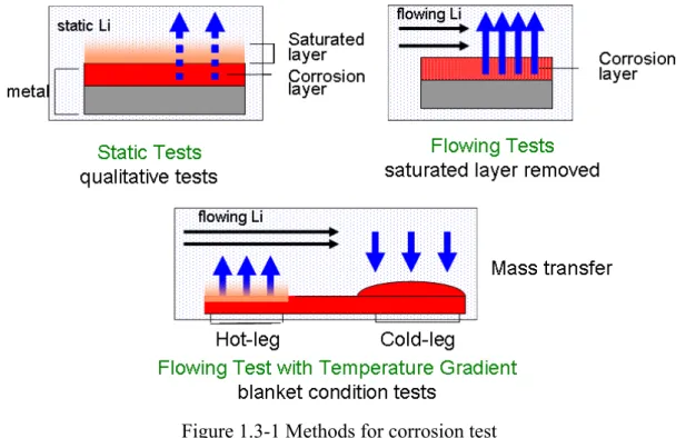
1.3.3 The methods for testing corrosion performance of materials in Li
The corrosion behavior can be studied from static isothermal liquid-metal in vessels or capsules as well as from circulating systems such as thermal-convection loops (TCLs) and forced circulation loops (FCLs), as shown in Fig. 1.3-1.
Exposure to static lithium systems have been carried out to investigate the characteristics of the various reactions between the environment and the material and to study the exposure condition and material variables on the interactions. Exposure to flowing lithium in a loop test has been carried out to investigate the dissolution and mass transfer behavior of structural materials. TCLs, with low flow speed, were used to study the corrosion behavior and mass transfer under temperature gradient. On the other hand FCLs with pump can makes the velocity of Li flow controllable. The corrosion behavior in FCLs is more similar to self-cooled blanket systems.
Figure 1.3-1 Methods for corrosion test
1.4 Research status of compatibility of iron based materials in Li
1.4.1 Corrosion
Several studies have been conducted to evaluate the influence of material and system parameters on the corrosion behavior of austenitic and ferritic steels in liquid lithium environment. The principal mechanisms of corrosion of materials in a liquid metal environment are dissolution, intergranular penetration, interstitial-element transfer, and mass transfer due to thermal and concentration gradients.
Table 1-4 the corrosion data of ferritic and austenitic steel in liquid Li
Metal Materials Temp. (ºC) Flow rate Exposure time (h)
Estimated corrosion depth (μm/year )
Reference
Fe-9Cr-Mo 372 1 L/min 6000 0.05 [56] Fe-12Cr-1Mo 372 1 L/min 6000 0.09 [56]
Fe-9Cr-Mo 427 1 L/min 7000 0.15 [41] Fe-12Cr-1Mo 427 1 L/min 7000 0.17 [41]
Fe-9Cr-Mo 538 1 L/min 3500 0.6 [56] Fe-12Cr-1Mo 538 1 L/min 3500 0.7 [56] Ferrite
steels
Fe-12Cr-1MoVW 600 0.025m/s 7000 3.3 [40] Fe-17Cr-13Ni-2Mo- 427 1 L/min 7000 6.3 [41] Austenite
steels Fe-14Cr-16Ni-2Mo 427 1 L/min 7000 9.5 [41]
The corrosion rate of ferritic and austenitic steels in Li was presented in Table 1-4. According to previous results, the corrosion rate of the ferritic steels in lithium is more than one order of magnitude lower than that of austenitic steels. The corrosion behavior of ferritic steel, Fe-12Cr-1MoVW, was investigated by P.F.Tortorelli in a convection loop made by the same materials. [39, 40] The N concentration was controlled to 30~100Wppm by a cold trap. The dissolution kinetic of ferrite steels in Li obeyed linear
law, as shown in Fig. 1.4-1. O.K.Chopra’s experiment agreed that the weight loss of ferrite followed a linear increase with the exposure time.[41]
Figure 1.4-1 The weight loss versus exposure time for Fe-12Cr-1MoVW in Li[40]
The dissolution rates for austentic stainless steels reached steady-state (time-independent) values after an initial period of 1500 to 3000h [42-44] This type of dependence was described in Fig. 1.4-2. The initial stage (stage A) of high dissolution rates corresponds to the formation of a ferrite layer which results from preferential dissolution of nickel from the surface of the austenitic steels. The steady-state regime (stage B) is characteristic of the dissolution of an austenitic stainless steel having a ferritic surface layer that is depleted of nickel.
Figure 1.4-2 corrosion of austenite steel in Li [39]
It was also reported that the 9Cr-steel (Fe-9Cr-Mo) showed better resistance than the HT-9(Fe-12Cr-Mo) by O.K.Chopra.[41] The average dissolution rates for both HT-9 and Fe-9Cr-1Mo steels are 6.3 and 0.15μm/yr at 427ºC, respectively, when N concentration was lower than 100wppm. In another experiment [45], these values of dissolution rates obtained in a cold-trapped forced-circulation lithium loop are consistent with the rate of 0.5μm/yr observed for HT-9 alloy in a lithium thermal convection loop at 460ºC. The N concentration in lithium in the latter test was reported to be < 100 wppm.
1.4.2 The effect of impurities in Li
The impurities, such as N, O, H, in Li affect the corrosion behavior of steels in liquid Li. The solubility of transition metals is enhanced by the presence of dissolved non-metals. Among them, the strong impact of N was highlighted. Experimental results showed that austenitic and ferritic steels were very sensitive to the N concentration in both flowing and static condition.[41,46-48] Chopra pointed out that when the N content increases from 100ppm to 300ppm, the dissolution rate increase by factors of 1.5 to 3 in a lithium FCL system operating at 360 to 482ºC[41] A nitrogen-alloyed Cr-Mn steel exposed to static lithium at 873 K formed a Li-Cr-N compound at the grain
boundaries.[49] A ternary nitride, Li9CrN5, was found on the surface of Type 316 SS that was exposed at 475°C to nitrogen-saturated lithium.[50,51] These could lead to possible selective dissolution of Cr when the structure materials are exposed in Li containing high level of N.
The C transfer between the steel and Li has a strong impact on the mechanical properties of structural materials. The carburization or decarburization phenomena are caused by the difference in chemical potential of C in Li. The chemical reaction between N and C in Li could enhance the C dissolution from the steels. The chemical reaction of N in Li was investigated by R.J. Pulham[51]:
4 Li3N + Li2C2 = 2 Li2NCN + 10 Li 2 Li3N + Fe = Li3FeN2 + 3 Li 5 Li3N + Cr = Li9CrN5 + 6 Li
1.4.3 The influence of steel composition on corrosion in Li
Because of different solubility of alloy elements in Li, the composition of steel influences the weight loss and corrosion rate of materials in Li. Without the effect of impurities, the solubility of elements in Li dominates the corrosion behavior of steels. The solubility values of the major steel elements are shown in Fig 1.4-3 [52-53].
Figure 1.4-3 the solubility of main alloy element in Li The N concentration: 50~100ppm [52]
As shown in the figure, the solubility of element in liquid metal increases with the temperature. So the increase of temperature generally enhances the corrosion. The different solubility of various alloys elements is the main reason for the selective dissolution during the exposure in liquid metal. The high solubility of Ni indicates that the corrosion rates increase with an increase in the nickel content of the material.[54,55]
The selective dissolution of alloy element causes not only weight loss, but also microstructure change and degradation of mechanical properties. The microstructure of 316SS after exposure to lithium at 600ºC for 8000h was presented in Fig. 1.4-4.[39] A porous ferrite layer was observed on the surface of specimens. It was reported that loss of Ni was the main reason caused the phase change from austenite to ferrite. The ferrite layer was very weak because of the high porosity, and it can easily spall under high liquid velocities, thermal transients, or cyclic straining. The formation of a porous ferrite layer has a significant effect on the mechanical behavior of the structural components made by austenitic stainless steels.
Figure 1.4-4 316 stainless steel exposed for 8000h in flowing Li at 600ºC
1.4.4 Compatibility of RAFM with Pb-Li
Studies were carried out on compatibility of RAFM steels with flowing Pb-Li. The past data are summarized in Table 1-5.[57–61] At 480ºC, the evaluated corrosion rate of RAFM steels is less than 100μm/yr in Pb-Li, although the test periods changed from 4500h-12000h. It indicates that the weight loss of RAFM increases linearly with the exposure time. It should be noticed the corrosion rate significantly increases with increasing the test temperature: 700μm/yr at 550ºC. [58] As for the flow rate effect, high flow rates resulted in a high corrosion rate, indicating that the flow rate needs to be suppressed to reduce the corrosion rate.
Table 1-5 corrosion data of RAFM steels in Pb-Li
Materials Temp. (ºC) Flow rate Exposure time (h)
Estimated corrosion depth (μm/year )
Reference
EUROFER 97 480 0.3 m/s 12000 90 [57] EUROFER 97 550 0.3 m/s 1000 700 [58] Optifer, MANET1,
F82H-mod.
480 0.3 m/s 6000 100 [59]
EUROFER 97 480 0.01 m/s 4500 40 [60]
It was reported that it took time for Pb-Li alloy to wet whole surface of specimen during exposure. The wetting issue could result in an apparent low corrosion rate at the first stage of experiment because the corrosion might only occur in the section where the steels contacted with Pb-Li. The period of wetting depends on the temperature [57] and surface condition of specimen, such as original oxide layer [62]. Fig.1.4-5(a) and (b) shows the metallographic observations of EUROFER 97 after typical corrosive Pb-Li attack for different exposure time. As shown in 1.4-5(a), the surface of sample was all covered with the Pb-Li alloy, indicating that the specimen was completely wetting with Pb-Li alloy after exposure for 1500h. In Figs.1.4-5(b), the SEM micrographs obtained on the cross-section of the 3000h tested samples are reported. As presented in the figures, a layer about 1 μm thick seems to detach from the surface of the steel. At the interface between the layer and the bulk material, voids could be observed, and the EDX analysis indicated that the layer was Cr depleted. The experiment in other system also proves that the dissolution of Cr and Fe from RAFM in Pb-Li is the major mechanism.
1.4-5 Cross section of Eurofer97 after exposure in Pb-Li [60]
The corrosion of different RAFM in Pb- Li was compared by Konny.[58] A summary of the maximal corrosion attack result from MANET I, Optifer IVa, F82H-mod. and EUROFER 97 was given in Fig.1.4-6. The lines for each alloy type were inserted by optical fitting to illustrate the time dependency. According to figure, the corrosion line of Eurofer97 is 10-20% lower than other RAFM steels. This cannot be explained by the chemical dissolution of alloy elements, because these alloys have very similar alloy composition. Probably the minor alloy elements, such as Ti and N, or low impurity level in steel are responsible for the difference. It is also influenced by
1μm
initial oxide layer on the surface of specimens. It was reported that the initial oxide layer delayed the onset of corrosion.[62]
Figure 1.4-5 comparison of RAFM steels in Pb-Li
1.5 The object of this work
1) The purpose of the present study is to examine the compatibility of RAFM steels with liquid Li in static and flowing conditions with respect to :
- Corrosion rate
- Mass transfer and compositional change - Microstructure
- Mechanical properties
2) Based on the experimental results, mechanism of the compatibility will be explored, including model analysis
3) Feasibility, critical issues and emphasis in the development of RAFM-Li blanket will be discussed
Chapter 2
Experiment
The compatibility issue of structure materials RAFM steel with liquid Li was studied in several aspects,
1) Comparison of different materials to investigate the influence of alloy elements 2) Static experiments to explore the kinetic weight loss of RAFM steel in Li
3) The corrosion behavior of RAFM steel in flowing Li
4) The compositional effect of the container materials on corrosion behavior of RAFM steel in Li
2.1 The composition and pretreatment of specimen
In this study, Fe-Cr-W based RAFM steel, JLF-1, was selected as the test material. The composition of JLF-1 is listed in table 2-1. For comparison, pure Fe and Fe-9Cr were also used in this experiment. Their compositions are presented.
Table 2-1 the composition of materials (EDS analysis, wt %)
Fe Cr W
JLF-1 balance 8.9 2.0
9Cr balance 9.11 0.11
Pure iron 99.99 - -
JLF-1 specimens were heat-treated at 1050ºC /3.6ks/air cooled (normalizing) and 780ºC /3.6 ks/air cooled (tempering). Pure Fe and Fe-9Cr were rolled, annealed at 700 ºC. All materials were prepared as coupon specimens. The size of coupon specimens was 26×5×0.25mm, as shown in Fig. 2-1. The surfaces of the specimens were mechanically polished with No.180, No.40 and No.600 sand paper before the experiment.
Figure 2-1 the size of coupon specimens
2.2 The procedure of the experiments
2.2.1 The application of Li
The high purity Li was ordered from market. The composition provided by company is showed in table 2-2. It is well known that the Li is very sensitive to air and water. Li can strongly react with water in room temperature and absorb O2 and N2 to form compounds. Especially, the N has a strong impact on the corrosion behavior of steel in Li.[48-50] To suppress the effect of impurities, the preparing work of experiment was carried out in glove box filled with argon whose nitrogen level was less than 1ppm., as shown in Fig. 2-2.
Table 2-2 Chemical composition of Li (wppm)
Na Ca Fe K Si N
Li 40 40 10 10 50 40
After the experiment, flowing water was used to remove the Li adhere to the specimens and the experiment systems. As the result of strong reaction between H2O and Li, heat and irritant gas was released during the cleaning. The cleaning with water not only removes Li, but also dissolves probable corrosion products formed on the specimens. It was reported that the corrosion products, such as Li9CrN5 and LiFeN2, may play an important role during the Li exposure.[49] The corrosion product layer can
isolate the metal substrate from liquid Li and prevent the development of corrosion. To investigate the effect of the corrosion products, some specimen was cleaned by dry ammonia to reserve the corrosion products. The Li dissolves in ammonia and form a dark blue solution and the corrosion products remained on the surface of specimen.
Figure 2-2 The glove box
2.2.2 Expsoure to static Li
After Li was melted, the coupon specimens were doped into the Li in a container. Holders or wires were used to fix the specimen to prevent them from attaching with each other. In most cases, the static exposure experiments to liquid Li were carried out in a Mo container which was placed in a stainless steel autoclave. Fig.2-3 shows the Mo container, holder and autoclave. For each experiment, 10 specimens were exposed in 100ml Li, and the ratio of Li volume VLi (cm3) to total surface area of specimens S (cm2) was around 4 (cm).
Figure 2-3 the Mo container, holder and autoclave
2.2.3 Exposure to flowing Li
The corrosion behavior in flowing condition is different from that in static condition. The corrosion process, such as erosion and mass transfer in flowing Li, are closer to the reality in reactor. In this work, Flowing tests were carried out in a thermal convection Li loop facility, which was made of SS 316L stainless steel and was composed of the loop, a Li tank and a heating system. The detail of the loop was reported in a reference.[24] A schematic diagram of the facility is shown in Fig. 2-4.
Container (Mo)
3cm
Specimen holder (Mo)
10 JLF-1 Specimens for each experiment
Glove box and experiment system The pot and Mo container
Figure. 2-4 The thermal convection loop
The inventory of Li in the loop was 200ml and the estimated flowing velocity was 0.05 m/s. The loop was divided into four regions by the temperature difference: hot-leg region 3; cold-leg region 1; transition temperature parts, region 2 and region 4. Specimens were fixed by Mo wires at each position. The impurity concentration in the loop test was expected to be comparable with the static experiment because of the similar preparing procedure. The size and surface condition of the specimens were common to those for the static exposure. After Li exposure for 250h, liquid Li drained away from the loop to the drain tank. The loop was disassembled and Li remained on surface of the specimens and the loop interior was cleaned by water.
The velocity of loop was given by following equation[24]:
∑ − ∑
−
+
= −
ζρ
ζρ
ρ
ρ
μ
μ 2 ( ( T ) ( ))
v
2 12 m
m
gh T
Li flow
350mm 26mm Specimen
tank
Heater
Region 1 400ºC
Region 4
Region3 500ºC
Region 2
92mm
115mm
77mm
μm — the loss of friction g — the gravity
h — the height of vertical part
ρ(T1) — the density of Li in high temperature ρ(T2) — the density of LI in low temperature ζ — the loss of shape of loop
:
2.2.4 The methods of analysis
Many analytical methods were applied to characterizations of corrosion. The change of weight before and after exposure was measured by the electro-balance with accuracy to 0.01mg. The microstructure and composition were analyzed by transmission electron microscopy (TEM), electron diffraction (ED) and scanning electron microscopy (SEM) with energy dispersive X-ray spectroscopy (EDS). The change of hardness was detected by Vickers hardness meter with a load of 10gf. The contents of C and N in JLF-1 alloys at various conditions were analyzed by chemical method. The surface of specimen was analyzed by X-ray diffraction (XRD) to identify the structure of corrosion product.
Chapter 3
Comparison of corrosion behavior of JLF-1,
pure Fe and Fe-9Cr in liquid Li
In this study, the compatibility of RAFM with lithium was investigated including comparative examinations using binary Fe-Cr alloy and pure iron.
3.1 The experimental condition
JLF-1(Fe-9Cr-2W-0.1C), a pure iron and a Fe-9Cr binary alloy were used for the experiment. The facility for static experiment and the pretreatment of specimen and were introduced in chapter 2.
The experimental conditions were listed in table 3-1. Pure iron, Fe-9Cr and JLF-1 were exposed to lithium at 700ºC for 100h (test A) to study the influence of alloy elements. Another group of JLF-1 specimens were exposed in lithium for 100h at 600 ºC and 700 ºC (test B) to study the influence of temperature.
Table 3-1 The experimental condition
Group A Group B
Materials
JLF-1 Fe-9Cr Pure Fe JLF-1
Temperature 700 ºC 700 ºC 700 ºC 600 ºC 700 ºC
Exposure time 100h 100h 100h 100h 100h
Clean method NH3 NH3 NH3 NH3, H2O NH3, H2O
The specimens in group A were cleaned by ammonia after the exposure in static Li followed by surface analysis. In group B, the specimens were cleaned by ammonia and water in turn and the weight change was measured after each step. In addition, JLF-1 as received was annealed in vacuum for 100h at 600 and 700ºC to examine the effects of thermal history.
3.2 The results and discussion
3.2.1 Weight loss and selective dissolution
The weight changes during the tests at 600ºC and 700ºC for 100h are shown in Table 3-2. After exposure for 100h, pure iron and Fe-9Cr gained weight, while JLF-1 lost weight. This indicates that faster corrosion took place at JLF-1 during lithium exposure. Small corrosion occurred on JLF-1 specimen at 600ºC. The corrosion rate after water cleaning is 0.0046mm/a. (Note that constant dissolution rate is assumed for the estimate). In the present experiment, water cleaned specimen had higher weight loss than ammonia cleaned ones, due to removal of the surface corrosion products by water.
Table 3-2 Weight loss and the surface composition of specimens exposed to Li for
* Constant weight change rate during the immersion was assumed
** This seems to be the result of Cr deposition from Li during the cooling period (A) JLF-1, pure iron and 9Cr were exposed in the same lithium pot
(B) Only JLF-1 was exposed in lithium pot
The surface composition change derived by EDS measurement from the normal direction to surface is listed in Table 3-2. As shown in Table 3-2, depletion of chromium
Ammonia cleaning
Water cleaning
Surface composition (EDS result) Materials/exposure
temp. Weight loss (g/m2h)*
Weight loss
(g/m2h)* Fe Cr W C JLF-1/bef.experiment − − 89.0 8.9 2.0 0.1
Fe/ 700ºC -0.021 Not available 96.4 1.7** − − Fe-9Cr/ 700ºC -0.0075 Not available 92.1 6.3 − − JLF-1/ 700ºC(A) 0.0075 Not available 93.5 5.4 1. − JLF-1/ 700ºC(B) 0.0327 0.1667 90.7 7.5 0.8 − JLF-1/ 600ºC(B) -0.065 0.0041 92.1 6.8 0.7 −
and tungsten was observed on the surfaces of all specimens exposed in liquid lithium except pure iron. Increase in Cr on the surface of the pure iron seems to be caused by the deposition from lithium during the cooling period. The depth of Cr depletion was about 5μm according to EDS line scan as shown in Fig. 3-1. The selective dissolution of both Cr and W is thought to enhance the weight loss of JLF-1 relative to that of Fe-9Cr and pure iron.
Figure. 3-1 Cross section EDS line scan on JLF-1 (Test A) and Fe-9Cr after exposure to Li at 700ºC for 100h
3.2.2. Phase transformation and hardness reduction
The surface morphology of JLF-1 (ammonia clean) exposed at 700 ºC is shown in Fig. 3-2. Clear grain structure was observed on the surface of the specimen exposed in Li for 100h at 700ºC. Spongy corrosion product layer covered the surface of the specimen after cleaning with ammonia. XRD was carried out to find out the composition of the corrosion products, as shown in Fig. 3-3. XRD result showed that the surface corrosion products were mainly composed of Li2CO3. Triple compound Fe-Mo(W)-C was also detected on the surface of specimens These corrosion products disappeared during cleaning with water. It is clear that phase transformation occurred at the surface of JLF-1 with martensite structure changing into a ferritic phase. This phenomenon was not found on the specimen that was annealed in vacuum at the same temperature for 100h, as shown in Fig. 3-2. No phase transformation was observed on JLF-1 after exposure at 600ºC.
(a) (b)
a. JLF-1 exposed in Li at 700ºC for 100h b. JLF-1 annealed in vacuum at 700ºC for 100h
Fig.3-2. SEM micrographs of JLF-1
Figure 3-3 XRD result of corrosion products on the surface of specimen exposed at 700ºC for 100h
The phase transformation has also been observed inside the specimen. Fig. 3-4 (a) and (b) are the cross section SEM pictures of JLF-1 exposed at 700ºC in test A and test B respectively. The phase change from martensite to ferrite was observed in both A and B situation. Especially in test B, the phase transformation depth reached 100μm after exposure in Li at 700 ºC for 100h. The martensite structure only remained in the center of specimens as seen in Fig. 3-4 (b). The phase change from martensite to ferrite was supported by TEM results. Fig.3-5 (a), (b) and (c) showed the TEM picture of JLF-1 before exposure, after annealing in vacuum at 700ºC for 100h and after exposure in Li
at 700ºC for 100h (Test A) respectively. It is clear that the microstructure change occurred on JLF-1 specimen exposed in Li 700ºC for 100h. The fine lath structure converted to ferritic structure in the TEM picture. Furthermore, the carbide almost disappeared in the area of phase change area. On the other hand, the annealing in vacuum led almost no change on the microstructure of JLF-1. This indicated that the phase change from martensite to ferrite was not caused by heat treatment, but by the Li attack.
a. Test A b. Test B
Fig.3-4. Cross section SEM and TEM images of JLF-1 exposed Li at 700ºC for 100h for the two tests.
Figure 3-5 TEM picture of JLF-1 (a) as received (b) annealed at Annealed at 700ºC for 100h (c) after exposure in Li at 700ºC for 100h
a. As received b. Annealed at
700ºC for 100h
c. Li exposure at 700ºC for 100h
Martensite
Ferrite
1μm 1
μm 1μm
3.2.3 Degradation of mechanical properties
Figure 3-6 shows hardness change with depth before and after exposure to lithium. The hardness reduction occurred on JLF-1 and Fe-9Cr at 700ºC. For Fe-9Cr, the softening seems to be caused by Cr depletion because the softening depth is close to Cr depletion range of 5μm. In JLF-1, phase transformation played a dominant role for the hardness. The depth of softening is consistent with the phase transformation depth. By the carbon dissolution and phase change, the hardness decreased from 250 to 140Hv. In the case of test B (700ºC), the hardness of JLF-1 at the area where the phase change occurred was close to that of Fe-9Cr.
Fig.3-6. Depth dependence of hardness
This implies that W has small impact on hardness in single ferritic phase. The fact that the hardness at the center of the specimen in test B is between that of the martensitic and ferritic phase implies that the phase at the center is mixture of the two phases. For pure iron, hardness was kept constant because neither phase transformation nor selective
a. b.
c.
dissolution of alloying element occurred. Almost no hardness change was detected on JLF-1 exposed at 600ºC.
The chemical analysis of JLF-1 was carried out and the result is listed in Table 3-3. Two third of carbon in JLF-1 (test B) dissolved into liquid Li at 700ºC for 100h. Martensite can be converted to ferrite when carbon is removed. Thus, the loss of carbon is expected to be the major reason for the phase change in this experiment.
According to thermodynamics graph in Fig. 3-7,[8] the order of stability of these compounds is at 700ºC is V2C > VN > Li3N > L2C2 > Fe3C. It indicates the tendency that V should get C and N, while Fe should lose C during lithium exposure.
Table 3-3. Chemical analysis result (wt %, JLF-1 specimens in test B)
Materials C Cr W
Before exposure 0.09 8.92 2.00
Li 700ºC 100hr 0.03 8.88 1.95
Li 600ºC 100hr 0.10 8.89 1.99
-2 50 -2 00 -1 50 -1 00 - 50 0 50
0 50 0 10 00 1 50 0 20 00 2 50 0 30 00
① em pe rat ur e( ºC )
Gibbs free energy (kJ/mol)
L i2C2
③ N Fe3C
③2C Li3N
Fig.3-7 Thermodynamic data of several compounds in Li[8]
3.3 Summary
At 600ºC, relatively small corrosion occurred on JLF-1 exposed to lithium. Neither phase change, nor carbon depletion was found. On the other hand, JLF-1 was largely influenced by the exposure at 700ºC, including depletion of carbon and chromium and resulting phase transformation from martensite to ferrite. Hardness reduction was caused by the phase transformation and element dissolution
The corrosion of JLF-1 is more significant than that of Fe-9Cr and pure iron at 700ºC. The selective dissolution of Cr, W and C into lithium seems to enhance the corrosion.
Chapter 4
The compatibility of JLF-1 in static and flowing
Li
The corrosion behavior of the RAFM steel, JLF-1, in a static Li was investigated preliminarily in chapter 3. The corrosion of the JLF-1 was summarized as selective dissolution of C, Cr and W, and phase transformation from martensite to ferrite because of C depletion. The depth of the phase transformation was estimated to be 100μm for JLF-1 exposed in Li for 100h at 700ºC, while no phase change occurred at 600ºC for 100h. The structure change was considered not to be the result of thermal history effects but the chemical effects, because no phase change was observed on the specimen after a vacuum anneal with the same temperature history. However, the corrosion and the depth of the phase change in the static experiment can be underestimated because saturation could be formed around the specimen, which might suppress further corrosion in the static test condition.
The purpose of the present study is to investigate further the corrosion characteristics and phase transformation phenomena of JLF-1 in blanket relevant conditions. Various static experiments were carried out at 500 ºC and 600 ºC for longer exposure time and a corrosion test for JLF-1 in flowing Li in a thermal convection loop was performed at 500 ºC.
4.1. Experimental condition
The detail of the static test facility was introduced in chapter 2. The surfaces of JLF-1 specimens were mechanically polished before the experiment. Static exposure experiments to liquid Li were carried out in a Mo container with Mo specimen holders, which were placed in a stainless steel autoclave. The experimental conditions are summarized in Table 4-1.
Table 4-1. Experiment condition
Static exposure Flowing exposure
600 ºC 500 ºC 500 ºC

![Figure 1.1-4 the cross section of 6 Li and 7 Li [25]](https://thumb-ap.123doks.com/thumbv2/123deta/6157844.103689/16.892.171.645.539.1007/figure-cross-section-li-li.webp)
![Table 1-2 The properties of liquid metal breeder [24]](https://thumb-ap.123doks.com/thumbv2/123deta/6157844.103689/22.892.126.775.305.731/table-properties-liquid-metal-breeder.webp)

![Figure 1.4-3 the solubility of main alloy element in Li The N concentration: 50~100ppm [52]](https://thumb-ap.123doks.com/thumbv2/123deta/6157844.103689/31.892.273.616.135.536/figure-solubility-main-alloy-element-li-concentration-ppm.webp)


