NII-Electronic Library Service Mmto:ns or SiGxx:
INeT:TvTs or TrctNoLoGy
Vor.
IS,
Ne. 1,19s4OiFHydraulic
Servo
System,
Design
andAnalysis
Sadao
ISHIHARA'
Preface
This
paperis
a part of the manuscriptfor
the symposiumheld
by
The
Scientists
&
Engineers
Society
in
Republic
ofChina
onNov.
23,
1982.
1.
Introduction
Some
fundamentals
whichhave
much concerns to the following paragraphs areex-plained
here.
1.1
Types
ofServo
System
andStationary
Error
Type
of servo systemis
classified by a number oflfs
in
openloop
transferfunction.
For
example,if
the transferfunction
canbe
writtenin
following
form,
nis
called thetype number.
K
G(S)=
s.(1+Ts) , n=O, 1,2, etc..
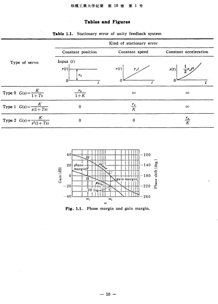
Stationary
errorhas
a close relation to the type number, and isgivenin
Table
1.1.
In
oil-hydraulic servo system, type 1is
most popular,because
hydraulic
actuatoris
essentially anintegrating
unit.1.2
Stability
Stability
is
animportant
factor
for
a servo system, and issometimes inconsistenttothe stationary error which ismentioned above.
Integration
improves
accuracy,but
on the contrary, itcontains a phase lag of 90degree,
so
it
has
tendency to reduce stability.
There
are many ways tojudge
stability, such asRouth,
Hurwitz,
and Nyquist. Butin
thispaper,Bode
plot
is
usedfor
a practical purpose.Phase
margin and gain marginare shown
in
Fig.
1.1.
There
are rnany ways to increase stability, such as phase lead network, rate feedback,and so on.
1.3
Nichols
Chart
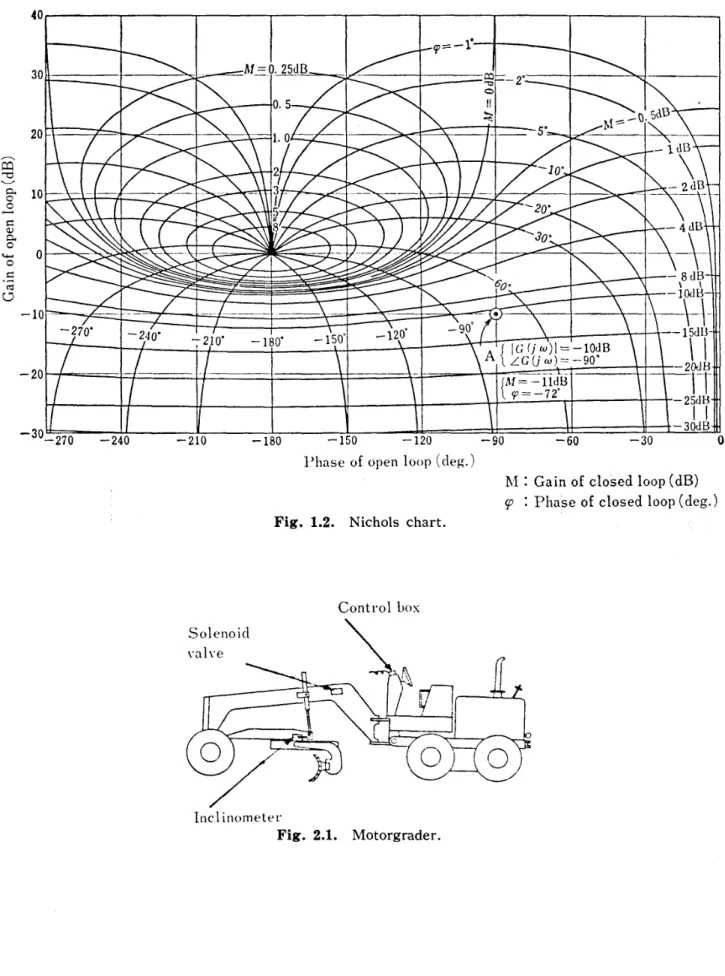
Open
loop
data
and closeddata
canbe
changed reciprocally to each otherby
Nichols
chart as shown
in
Fig.1.2.
2.
Semi-Automatic
Blade
Centrol
Deviee ef Motorgrader 2.1General
Descriptien
Motorgrader
is
akind
of construction machinery, which main purpose are road finish,ground surface finish,snow-removing, etc..
Operation
is
alittle
cornplicated, andit
is
diMcult
for
an unskilled operator.Motor-grader equipped with semi-automatic
blade
controldevice
is
shownin
Fig.
2.1.
This
device
is
composed of controlbox,
solenoid valve andinelinometer.
By this device, operation*
diutII:\"
tyN
198349A 6 Hectt
Shonan Institute of Technology
NII-Electronic Library Service ShonanInstitute ofTechnology
ie
ecI#
]k\aff
M
18#
ag
1e , -.-.・ ,.・..rt. t /.t tt . it .
t
-becomes
easier, and accuracy of roadfinish
is
improved
very much.2.2
Blade
Control
Device
Hydraulic
eircuitis
giVenin
Fig.
2.2,
vvhereO
controllever-
oflefti
cy]inder,@
left
cylinder,
@
controllever
of right cylinder,@
right cylinder,e
blade,
@
inclinometer,
¢ control
box,
e
solenoid valve,@
flow
control valve.
The
blade tiltingangle iscontrolled automatically at a preset value by thisdevice,
so that ]evellingoperation can easily
be
accomplishedby
theleft
blade
controllever
only.An
operator needs only to watch and control the blade height of leftend.It
makes not onlyblade
conyrol easier,but
alsoimproves
finishing
accuracy two times cornpared toordinary manual operation.
Considering
cost and maintenance, solenoid vatveis
used, so the controlis
essentiallyON-OFF
control.To
avoid a bad effect ofON-OFF
control,PWM
(Pulse
WidthModula-tion)
is
applied, and the system canbe
considered approximately equivalent to proportionalcontrol.
2.3
Analysis
ef theSystem
Block
diagram
is
givenin
Fig.
2.3.
Symbols
are asfollows.
c:
input
angle of controlbox,
Sinx1oo%
{V)
e:
output angle ofinclinometer,
Sinx1oo%
(V)
e: error signal, e=c-0
(V)
K,: gain of
OP
amp,PWM
i:
current to solenoid valve
Q:
flow
rate of solenoid valve(cm3i's)
pt]
cylinder stroke(crn)
A:
cylinder area(cm2)
T: time
lag
of solenoid valve(s)
K2: gain of
blade
(radlcm)
e:
blade
angle(rad)
K5:
gain ofinclinometer,
Sinx100%
(V!rad)
Characteristics
ofPWM
andON-OFF
control rnay not be easy to be understood.So
it
is
better
tobe
transformed equivalentlyinto
more understandableform.
Principle
ofPwu
is
shoWnin
Fig.
2.4.Error
signal(e)
decreaseS
with the time(t).
Hacksaw
wave, which periodis
T
andmaximurn
height
is
eMis
super-imposed on the error signal.During
eis
greater than e..,solenoid
is
continuouslyON,
and pulse width tw.is
equal t'oT,
tw.=T.When the error signal across the
hacksaw
wave, where error signalis
e., pulse widthtw.
becomes
Txe./e,..
That
is,
for each period ofT,
pulse Width(tw.)
is
proportional toerror
(en)・
Mean
flow
rateQ
is
asfollows.
Q=Qtw./T==(QfeM)e.
Kl'
=Q/eMis
equivalent gain ofPWM
andON-OFF.
Equivalent
blockdiagram
isshownin
Fig.
2.5.
There still remains a non-linearfunc-tion,of saturation,
but
it
is
more easier to be under:stood than the .former.2.4
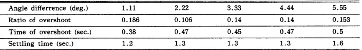
Result
Indicial
responseis
given
in
Fig. 2.6.Curve
presentslst
order lag, and the mosteffective
factor
is
time cpnstant ofinclinometeg.
.(T). ..,.... . .Test
resultis
givenin
Fig. 2.7. By the help of thisdevice,
accuracy of roadfinish
NII-Electronic Library Service
Oil-Hb,drauiicServo
System,
Design and Analysisis
improved
satisfactory.two
timescompared with a ordinary manual operation,and the testresult
is
3.
Synchre
Servo
3.1
General
Description
This
is
a rernote control system which will control automatically the angular motionof a
heavy
load
in
response to the synchro signalfrom
a controller.Schematic
is
shownin
Fig.
3.1.
The
centroller sends a comrnand signal by two speeds synchro, coarse signal of1speedand
fine
signal of18
speed.Two
signals areinterchanged
at6
degree
of coarse signal.
Synchro
differential
motor(5DM)
drives
a stroke control assmbly composed of pilotvalve and cylinder and speed error corrector.
The
cylinder controls the variabledisplacement
purnp, andhydraulic
motordrives
the]oad, and then angle of load
is
fed
back
to switching relay and differentialmotor.
This
systemhas
only oneintegrating
unit of hydraulic motor, andis
type1
servo.In
general, asit
is
explainedbefore,
type1
servohas
a stationary error at constant speed,but
in
thiscase, speed error corrector eliminates the above error.
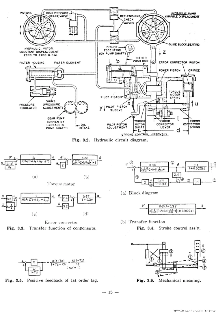
Hydraulic
circuitis
shownin
Fig.
3.2.
3.2
Analysis
of theSystem
(1)
Diferential
synchro torque motor
e,:
command signalfrom
fine synchro5Gl
e,:
feedback
signaHromfine
synchro5G3
0t: error angle, e'==ei-e,
(1)
e: rotation of rotor
J:
moment of inertiaof rotor'D: viscous
drag
coeMcient of rotor
T:
torque of rotor shaft
k,:
torque coeMcient of rotor shaftu: position of error corrector piston
d:
distance
between
torque motQr shaft and error correctorpiston
le,i:spring coeMcient of torque motor spring
Equation
of motion
T=k,(e,-e)+le,,("--d・e)d
ld2o,r'dtt+Dde,fdt=k,(e'-e)+k,,(u-d・e)d
Transfer
function are shownin
Fig.
3.3
(a),
(b).
(2)
Pilot valve and aylinder x:displacement
of pilotpistony: displacement of pilotpiston sleeve z:
displacernent
ofpower
piston a: length of link
b:
length
of Iinkc: length of torque motor arm '
kh:
valve cylinder coeMcient-kn
is
obtained frorn the following equation. ,(rad)(rad)(rad)(rad)O.OO08
(kgf・cm-s2)
O.3
(kgf・cm・s・rad-t)
(kgf・cm)
1.2(kgf・cm・rad-i)
(crn)
8(cm)O.3
(kgf・cmLi)
(2)(3)
(cm)
(cm)
1
(cm)
5.1
(cm)
6.4
(cm)
2.5
(cm)
'510
(s-i)
-3-NII-ElectronicShonan Institute of Technology
NII-Electronic Library Service ShonanInstitute ofTechnology Nff-* rk#rept eg188 ij1 e
h,=XV
P-EiA
A:
P:
F:
a: g: at: r:R:
&:
Thus
2+-2-
×le2Rxe'
'effectiye area of cylinder supply pressure
ayerage
load
of power pistonflow
coeficient of pilotpistongravity acceleration
equivalent width of circular port
specific weight of oil
resistance of pipe
line
(neglected)
input
amplitudek-aa'
V
2,g(4)
6.9
(cm2)
10.5
(kgf・cm'2)
16
(kgf)
O.8980
(cm-s"2)
1.46
(cm)
O.88
×107S
(kgf}cm"3)
(cm>
x==ce y=(a/b)zd2!dt=k,(x-y)==kh(ce-az!b)
(5)
<6)
(7)
Transferfunction
becomes as follows.Z(s>e(s) bcta
3.1
b1+
ale, S1+O.oo25
s
(8)
(3)
speed
error corrector
i:
length of error corrector lever
l:
distance
of error corrector pistonfrom
error correctorlever
hinge
k,2:
spring coeMcient of error correction springM':
mass of error correctorpiston
D':
viscousdrag
coethcient of error corrector pistonEquation of rnotion Mt(d2u/dt2)+D'(dut'dt)=k,,(de-u)+k,2(l21i"U)
2
(cm)
5.3
(cm)
1.2
(kgf・cm-i)
2
×10Jli
(kgf・cmJ'・s2)
O.45
(kgf・cmJi・s2)
(9)
Transfer
functions are shownin
Fig.
3.3
(c),
(d).
(4)
Tbrque motor and strcke control assemblyBlock
diagram
is
build
upfrom
Fig.
3.3
and equation(8>,
and isshownin
Fig.
3.4
(a).
This
contains a positivefeedback
oflst
order lag, and isapproximately transformed into(b).
Positive
feedback
of lstorder lag isexplainedin
Fig.
3.5.
If
KH
is
equal to 1,itwill bephase
lead
network with integral.
In
this application,it
changes a type1
servointo
type2
with phaselead,
soit
im-proves system performance as long as itisstable.
Mechanical
meaning isexplained inFig.
3.6.
Number
in
circleis
same as Fig. 3.4. An error angle(1)
makes the retation angle(2),
and then piston movement(3)
and error corrector lever movement(3')
follow.
These
NII-Electronic Library Service
Oil-Hlv,drauiicServo
System,
Design and Analysismake piston rnovement
(6)
by
springforces
(4)
and(5).
Spring
force(7)
is
fedback
posi-tively to the torque motor shaft.
Even
an error anglediminishes,
springforce
(7)
keeps
the rotation angle
(2),
so that the system can work without constant speed error.(5)
HZydrosratic
transmission
Q.:
flow
rate of variabledisplacement
pump(cm3-s-i)
S.:
flow
coeMcient ofPV
540
(cm3・s-i・cm-i)
Q.:
flow
rate offixed
displacement
motor(cmB・s-i)
ei:
flow rate of leakage(cm3・sLi)
Q,:
fiow
rateby
compression of oil(cm3.sui)
d.:
displacernent
of motor per radianO.8
(cmS)
O:
rotation angle of motor<rad)
1':
equivalent moment ofinertia
on motor shaftO.oo5
(kgf・cm・srr2)
P:
workinghydraulic
pressure(kgf・cm-2)
L:
leakageflow
coeMcientO.15
(cm5・s-i・kgf-i)
As
the purnp and motor are assernbledintegra]ly
in
one casing, oil passages are veryshort, and oil compression can
be
neglected.
Q,=O
Q.:=:S.・z=Q.+Qt
(10)
Q,.
=d.
dd9tr
(11)
1,
d20
P=
(12)
dm dt2Q,-L・P-f,'.`
d,"',e,
(i3)
Then
dip
,Ll,
d2p
Spa=dmdtTd.
dt2
(14)
Transfer
function
is
asfollows.
¢
(S)u
Sp/dm - 675Z(S) Us(1+
dL.J.L'
s) -s(1+O,Ol s)<15)
(6)
Totalsystem
Gear ratio from
hydraulic
motor to finesynchro isO.05.Block diagram of total system ismade from equation
(1),
Fig. 3.3,Fig.3.4
andequa-tion
(15),
andit
is
shownin
Fig.
3.7.
Bode
plotis
shownin
Fig.
3.8.
3.3 Experiment
(1)
,FVequenay resPonce
System
is
testedin
closedloop
condition,frequency
and arnplitude of sinusoidalinput
are changed. Measurement
is
done
by
potentiorneter and osciliograph.An
exampleis
shown in Fig. 3.9.
-5-Shonan Institute of Technology
NII-Electronic Library Service ShonanInstitute ofTechnology
in
e,(s)It
is
(3)
,.Static
3.4The
This
and they are
4.
30oo
ton 4.1GeneraE
This
sure vessel condition1
3
5
79
11
Slide
13
15
Test
17
4.2(1)
(3)
.(5)
(7)
(9)
(11>
(13)
(15)
(17)
(19)
re
st
=*)c4re
et ca 18#
ngClosed
1oopdata
are changed to openloop
data
by
Fig.
3.8,
Table
3.1
andTable
3.2.
(2)
indicial
responseIndicial
responseis
asfollows.
20.6(1+O.3s)
le
Nicholschart,andthey
are .glven
(16)
s[20.6{1+O,3 s)+s2I(-ig6ri)2+2xO.4 ×
(
lg6
)+1)(1+O.oo25
s)](1+O.Ol s)approximately changed
into
timefunction.
e,(t)=1+1.36
e-3i26' sin(3.59
t-O.832)(17)
Experimental
record isshownin
Fig.
3.10
andTable
3.3.
Static
accuracyacguracy
is
givenin
Table
3.4.
Conclusionmost significant
feature
of this systemis
the speed error corrector.system
is
very stable, and phase marginis
60
degree
andgain
marginis
20dB,
proper values
for
a seryo system.
Fatigue
Tester
Description
machine
is
a specialbig
fatigue
tester to test a thick platefor
boiler
andof neuclear plant.
It
can testthefull
size test piece underlow
cyclefatlgue
(Fig.
4.1).
Frame,
cylinder side2
Frame,
shaft side
Cylinder
piston4
Column
Large
shaft6
Nut
Spherical
washer8
Spherical
washerLocking
washer10
Rotating
device
base
12
Rolling
ball
Rotating
device
14
Shaft
supportpiece
16
Piston
connection
Hydraulic
cylinder18
Intensifier
Specification
is
shownin
Table
4.1.
Hydraulic
Cireuit
andCentrol
Sehematie
Hydraulic
circuit and control schematicis
shown inFig.
4.2.
Pressure
transducer(2)
Bridge
circuit
Arnplifier
(4)
Differential
transformerAmplifier
(6)
Amplifier
Differential
transformer(8)
Bridge
circuit
Amplifier
(10)
Servo
amplifier
Program
controller(12)
Funetion
generator
(14)
Hydraulic
cylinder
Arbitrary
function
generator
Servo'valve
・(16)
Flow
control valve
Accumulator
(18)
Intensifier
Solenoide
valve(20)
Pilot
operated valve
NII-Electronic Library Service
Oii-H),draulicServo
System,
Design and- Analysis
(21)
Pilot
operated valve '(22)
Solenoid
valve .(23)
Solenoid
valve(24)
Throttle valve
(25)
Trottle
valve(26)
Unload
vale
(27)
Relief
valve(28)
Zero
voltagedetector
(29)
Accelometer
(30)
Acceleration
sensor
Two
kinds
of control are available, one isadisplacement
control, and the otheris
aload
control, and they are selectedby
switchSl.
In
displacement
control,displacement
of both top and bottom sides of the testpieceare
detected
by
differential
transformers, and signals are sent to a bridge circuit andam-plifier,and their mean value isfed back to the servo amplifier.
In
load
control,pressure
atboth
sides of the cylinder are picked up by the pressuretransducer, and their difference is fed back to the servo amplifier,
because
Ioad force isproportinal to the
pressure
difference
of both sides of the piston.
In
the fatigue tester,ifthe btoken surfaces' of the test piece arepushed
against eachother, their surfaces will
be
damaged
and notgood
for
electronic microscopeinspection.
In
this machine, the broken pieces are separated imediately after breakage.
The
acceleration sensor pick up shock ofbreakage,
and the accelometer actuates thesolenoid valve
<22).
Oil in the left side of the cylinder(14)
goes through the solenoidvalve
(22)
and the throttlevalve・・(24), and entersin・the
tank.So
the piston movesleft-ward, and the broken test pieces are separated at once.
Wave
form
ofinput
signalis
selected by the switchS2.
Sinusoidal or triangular wavecomes from the function generator of
low
frequency
type, and arbitrary repeated waveform
comesfrom
the arbitraryfunction
generator.4.3 Hydraulic Systera . ..,.
Specification
is
shownin
Table
4.2.
High
pressure of 5ookgflcm!is
usedin
this system to makelarge
force
of quickresponse.
The
intensifier
makeshigh
pressurefrom
mediumpressure of175kgfXcm2.
It
works automatically by combination of two limit switches, the amplifier
(6),
the solenoidvalve
(19),
the pilotoperated valve(20)
andfour
check valves.
The
accumulatoris
also a kind ofintensifier,
andit
supplieshigh
pressure only whenthe
intensifier
ehangesits
movingdirection.
To
controllarge
hydraulic
power, combination of the servo valve and the largeflow
control valve is
dsed.
Minor
loop, which iscomposed of fiowcontrol valve, thedifferential
transformer
(4),
the amplifier<5),
the servo amplifier(10),
and the servo valve, makesflow
control very stable.
4.4
Control
Circuit
(1)
Block
diagram
Block
diagrams
of two control systems are shownin
Fig.
4.3 andFig.
4.4.
Definition
of symbolsare as
follow,
e:
input
signal to the system(V)
e,:
input
sigrial to the minorloop
(V)
i.:
input
current to the servo valve(mA)
x.: spool
displacement
of servo valve(cm>
eqr:spool
displacement
offlow
control valve(cm>
y:
displacement
ofpiston
<cm)
R:
load
pressure of piston(kgf!cm2)
Standard
premise condition ofdesign
is
asfollows,
-7-Shonan Institute of Technology
NII-Electronic Library Service ShonanInstitute ofTechnology
reecI* rt#reut eg18 8 or1 -e
Test
piece:2,OOOmm
length,1,OOOmm
width,1oomm
thicknessSpring
coeMcient of frame: 5.13× 10⁶kgf/cm
(2)
TVansfer
.ftenctionof
mtijor comPonents and synthesisof
thesystem
(a)
Amplifier
ofdisplacement
controlKl=54
(1)
(b)
Servo
amplifierG.
This
amplifier contains phaselead
network toirnprove
performance.
Kiai(TDs+1)
Ga(S)=
(2)
ai71Ds+1
Where,
KL=850,
cr,r-O.1,T.=O.Ol19
(c)
Servo
valve
XL(S)
-kv'tov2
(3)
Gn(S)
:4(s)
- s2+2C.to.s+to.2
Where,
to.=1oo radls,C.=O.7,
le.==O.oo133
cm!mA
(d)
Flow
control valve
Xf<S)
-lef..f2
Gi(s)=
(4)
XL(s)
-(1+T,s)(s2+er,bl,s+to,2)
Where,
Tlt:=O.77s,
tof=960rad/s,
gf==O.033,
kf=535
(e)
Hydraulic
cylinder(displacement
control)lectoc2
(5)
G,(s)
=
(1+TLS)<S2+2C;e(veS+cve2)
Where,
to.==38rad/s,Tl,==10s,
C,=O.O06,
k.=2.0
(f)
Differential
transforrnerKli==1.66Vfcm
(6)
(g)
Differential
transformerKl=O.333Vfcm
(7)
(h)
Minor loop
Closed
loop
plot of rninor loopis
shownin
Fig.
4.5.
(i)
Bode plot ofdisplacement
control system
Bode
plotis
shownin
Fig.
4.6.
Gain
marginis
about5dB,
and phase marginis
90
degree.
(j)
Amplifier
G,
To
increase
stability athigh
frequency,
G,
has
galn adjusmentby
low
passfilter.
G,(s)
=(1
+3
.2,,
),
(s)
Where,
tot=5radfs(k)
Hydraulic
cylinderG.'(s)
k.t(S2+?12
>toc2
Gc'(S)=(i+TL;)(s'W+'2c,6,s+w.2)
(9)
Where, k,'=1,OOO
(kgflcm2)/cm,
to,=17.6radls, w.=38radfs,T,=10s,
C,=O.O06
NII-Electronic Library Service
Oil-H),draulicServo
S},stem,
Design and Analysis
(1)
Bode
plot ofload
control system
Systern
can be adjustedin
many points of electric circuit.
A
typical characteristicsis
shownin
Fig.
4.7.
(m)
Accuracy
of waveform
Wave
form
is
pretty good as shownin
Fig.
4.8,
Strain
of test pieceis
also recordedfor
a purpose of material tester,but
it
is
not explained before, because itis
eutside ofthis servo system.
4.5
Conclusion
This
high pressure oil-hydraulic servo system satisfies the specification of thefatigue
tester,and
it
works very good.
Good
control performances are obtainedby
thehelp
of phaselead
network, minorloop,
low
passfilter,
and so on.
References
1) Sadao Ishihara: Analysis of a Hydraulic Servomechnism. Autornatic Control. Vol. 8, No.4, 1961.
2) Sadao Ishihara: Operating Force of Axial Plunger Pump. Measurement and Automatic Centrol,
Vo]. 1, No. 7, 1962,
3) Sadao Ishiharaancl I$ao Sugioka: Study on the ControlForce of a RodlessType VariableDelivery
Axial Plunger Pump.
Journal
ofJ.S.M.E,,
Vol. 29, No. 198, 1963.4) Sadao Ishihara: Multistroke RadialPistonMotor.
Journal
of J.S.M.E.,Vol. 74,No. 628,1972.5) Tornoo Ishihara, Sadao Ishiharaand Takeshi Takagi: Designof FluidPowerTransrnission.
SHA, 1967.
6) Sadao Ishiharaand Kazuo Uehara: Energy Saying in Hydraulic System of Hydraulic Excavator.
Journalof
J.S.M.E.,
No. 780-1,1978.7) Sadao Ishihara: Applicationof Oil-hydraulicsand Pneumatics inConstructionMachinery.
Journal
of Hydraulics and Pneurnatics Society,Vol. 3,No. 1,1972.
8) Sadao Ishihara and Mutsuo Shino: Application of ReliabilityTheory on Oil-Hydraulics,(1).Journal
of H.P.S,,Vol. 8, No. 3, 1977. Sadao Ishihara and Satoru Sasano: Application of Reliability
Theory on Oil-Hydraulics,
(2).
Journal
of H.P.S.,Vol.8,No. 4, 1977. Sadao Ishiharaand HiroshiShirnamura: Application of ReliabilityTheory on Oil-Hydraulics,(3).
Journal
of H,P.S., Vol. 8,No. 5, 1977.
9) Ryuji Itoand Sadao Ishihara: Applicationof Hydraulic and Pneumatic Servomechanism on
struction Machinery. Journalof H,P.S., Vol. 9,No. 3, 1978.
10) Sadao Ishihara: PistonPumps and Motors, Theory and Practice. OHM-SHA. 1979.
Shonan Institute of Technology
NII-Electronic Library Service Shonan 工nstitute of Teohnology
相模工業 大学 紀要 第 18 巻 第 1 号
Tables
andFigures
Table 1,1. Stationary error of unity feedback syste 皿
Kind of stationary error
Constant position Constant speed Constant acceleration
Type of serve lnput (’)
r(t) 0 ’ ) ’ ( 7 0 t r(t) 0
去
・・」
;2 t K Type O G(s}= 1十 Ts ro1 十K oo QQ KT
夕pel G(s}= s(1+ Ts) 0 彑 K ○ ○ K Type 2 G(s)= s2(1+Ts) 0 0 彑 40 20 霞 ε .E O8 −20 −−40 ω l Fig 。1。1.1
B’111
1
phase 鹽 ma 「91n総
o1
; }c’ 川li
它1
.gam,出・ ・幽L
… 幽 易1ll
田 c 呂 2010 αilI1i
I
ω ωユ 一100 驚 .−1408 ζ 憎一 180 暢 $ −220 2 氏 一260Phase rnargin and gain margln .
「
一 10 畄
NII-Electronic Library Service
Oit-ll),draulicServoSystem, Designand tAnatvsis
40 30 20
disg
losEg-. oo.ENo-10 -20 -30 -270 M=O.25dB g=-1' -t .5age11.si.
H-2' ' 5e .b."ts5dSxp 'LO tloe 1dBx"2aB - t--...-" .t.-- L '' 2:l--'u5B -20' 30' tt ..-. -x / -4dB.-...-8dBNt-]ouB ' ff0eH
. ut....].t ...-...t..t..-.t.r . --270'-24e' -15Q'-120d t"'--90 -180' A{](;rJ'a,)I=,--1edBZCCiill}=--90' --15dBu2oaB ...--L tt '{"'L==1i,iSB
1-l'-2suB"-3ouB
' -240 -210 -180 -150 -12e}'haseof open loop
(deg.)
Fig.1.2.Nicholschart.
-90 AI:9:
-60 -30
Gainef cleSed loop
(dB)
Pha'seof closed loop
(deg.)
o Controll)ox
Solenoid
valveo
A-s>
Nv
ri''
co)o Inclinometev Fig.2J.Motorgrader.-11-Shonan Institute of Technology
NII-Electronic Library Service Shonan 工nstitute of Teohnology
相模工 業大 学 紀 要 第 18 巻 第 1 号
山
Fig .2.2.Blade control device.
Inpntanglec (V) ÷ Error e (V} OP amp . i(A) So】enoid va ]ve
Q
(cm3 /s) 」 κ1 fPWM Cylinder y(cm ) Bla(】e Q ε 一 E eON −OFF e−「sAs Kz θ(rad ) Inc]inometer θ’{V〕 K31 十TsFig.2.3, Block diagram of blade control device.
一 12 − 一
NII-Electronic Library Service Oit-H),draulicServoS)'stem,Designand Analysis k --o esk=k tnm 'ase trxi9-es di=s )dim"Pvttu di=e -v"=lr
g--pt
6
gokkooj Time t Fig.T2.4.2'r3TPrinciple4TofPWM. ime t Timet cCV) e(V)ProportienalSaturation Kl-Qe,u Q(cm:ls) y(cm) e(rad) Q(? E,eLr e 'T-g.As K, e・(v,) K,1r7-sFig.2.5.Equivalentblockdiagrarn ofblade control device.
(i'1'[L,,.i
[I==
--.OlFig.
2.6234. Indicialt(sec)response.
-13-Shonan Institute of Technology
NII-Electronic Library Service Shonan 工nstitute of Teohnology
相模工 業 大 学 紀 要 第 18 巻 第 1 号 mm ±30 い O J: 台.9 ±
20
田ε羹
±1。 123456k ・!
b
.、 Con 七roU ,er Coarse 呂yllchro genera 七〇r 弸 Y:
ー
盆
1 Speed signa1 Fig.2。7。 Vehicle speed ..1
』. Test result , , MachineCoarBe synchro motor
Fiコユesynehro gener ユ七〇r 183peed
5M
signal ヒ L 一 Response 一 signal ノ ! , ! 「6 0 _ _ _! Fin6 庵 1Coarse l l I ’ 5Dr・1 .丶 、 b 7 「 聖 8 @1 i Coarse _fi rel3peed eでror correc 七
vFine reSPQn3e sig
1 iFig .
DL
C 〔 )arse
re3ponse si alSchematic of synchro se o. 工 o 一 Ele オc へ Hydr lj .cMec ica1 一14 一 N工工一Eleotronio LibraryNII-Electronic Library Service
Oil-HZydra"licServoSystem,Design and Analysis
"STowS-cbqtwe}
・...・;Nt . tt s t HtGH PRESSURE REUEtVALYE, xy-W LUt9!9mR GONSTANT OISPLncEMENrZERO TO 27eO R.P.U.FILTER
ELEMENr ]i''i' ・fR:l-.=-REPLENtSHIua CH[CKVALYES
---t-=""-/'Li=qm-t`
1Ecec"E"rJET"R" DITHERsH Rooigliz timaAULR2UttE MLAeua orsuLACtmettT ERROR t'' SLDE eLDCKpmttt3 FILTERHOU51NG PR!5REGU PVMP SHAFT) M・ER,(l
IEkl.lv
CORREeTOR PtSTON plsTONX
: v rr LNTAKE TORQUEMOTORSPRiNG Ail--ORtFteE"-iii
L
/
PrLOT PtSTON ADJUSTMENTTCROUMOTORSbSJIFTc -LC'tt?u COHRECTOR LEY[Ht t:TmosE aNtReASCEX LYd Fig. 3.2.Hydraulic diagram.ERftC"l
ffljilSPRVtG
ECTOR clrcult e' +atleEnE"sd ht "jS,.Ds-Cts+hsld2)e iila) eJ+ ao6e u+(dir+2iaKigS)+i 2 '1'oi'que motoril.b'i e'9 O.06 @e 3.1 z@ +'riJ,)52xO.4(ii")+1 1+O.O025s m 2.4 a-g.6[L ,.O,CD3.2o
2-1+O,3s ot ez +"d +!s2t 1 Mts'+Dls+(hpt+hs2)u '[cltt e+ a67u 2,4+1+O.3s z3,2 d/(a)
Blockd]agram e' O,61(1+C.3s) Z slGif)'-2so.4(et)+il"+o.oo2ss) Fig.3.3. Em'-v ('oi'i'eetovTransfer functionof conponents.
/'b'/ 'Fransferfunction ,t1Fig. 3.4.Strokecontrol ass'y. + Fig.3.5. +KH1+TsPositive .-tK" ±-LE.L(1T}.-ttC"±[lst.") d+Ts-KH Ts (KH=d)
feedbackof lstorder lag.
pK6
eFig.
3.6.q[]6
/P
..,.i-6-t-vEg ,-"Mechanical 'meanmg.-15-Shonan Institute of Technology
NII-Electronic Library Service Shonan 工nstitute of Teohnology
相 模工 業 大 学 紀 要 a61Cl+O.3S) Z 第 18 巻 第 1 号 ) 1 ( nO “ aUqE ) a ( e「 5〔(
th
),卜2属aヰく歯〕+1}く1+aoO25s〕Stroke control as5 ’y
9 675 φ
5 (1+0.015 )
(b)e’+
Total system
Fig .3.7. Total system .
4Q 密 2。 ε .E む ¢ . o
−20 Hydrostatic transm鳳ssm
轡
Gear ratio θ・+ 一 20,6(零+ O.35} θ。 52脚 2 ・2・α・愉 )・1}(1・α 。。蕊51〔1… 。1S〕 1 10 ω こr・cレ5ec ]Fig 。3.8. Bode plot of total system .
Input
Output
1 畳 l l l l l 1 1 5 1 1 } l I l
Fig .3。9. Frequency response .
− 16 一 (. 蚕DO 唱 ) 姦 7 [ uり gD に ‘ 山
誥
欄 欄 燗 噸 鱒 ’ 100 I I N工 工一Eleotronio LibraryNII-Electronic Library Service Oit-H),draulic Table3.1. Servo
S}'stem,
Frequency Design response and Analysis (amplitude3.3deg.) Frequency tu(rad,is)
Closedloop Open1oop
Gain Lil4'[(dB) Phase F(deg) Gain
IGI
(dB) Phase e(deg)O.98 1,94 2,68 5.559.5112.5515.00 o. L L o.-L-3.-5. 835957525251 o -4. -12. -44. -71. -85.-111. 446o3o 20.5 15.0 11.0 2,9-2.0-4.8-7,5 -180-158=14e-117-119-119.5-135 Table32.Frequencyresponse(amplitude 6,54deg,) Frequency w
(rad,・'s)
Closedloop Openloop
Gain
IMI(dB)
Phase y(deg) Gain[Gl
(dB) Phase e(deg)O,95 2.02 4.62 5.609.2412.30 o. L L-o.-2.-5. 2505581459 o -6. -29. -41, -74-106 9518 31 14.2 6.5 3.0-2,95-7.8 -1eo-128-123-110-115-131 Fig.3.10. Ilrl n 111 /: 11 1: [9 :E W :,ECE Transient reeponse rl [.t:.1:/ ,(angle ill! tl { gt・r diff.1.11 deg.)
-17-Shonan Institute of Technology
NII-Electronic Library Service ShonanInstitute ofTechnology
reecx*J<\rest
Table 3.3. Inag
18 dicialig
mlg
response Angledifferrence(deg.) Lll 2.22 3.33 4.44 5.55Ratioof evershoot O.186 O.106 O.14 O.14 O.153
Time ofovershoot(sec.) O.38 O.47 O.45 O.47 O.5
Settlingtirne(sec.) 1.2 1.3 1.3 1.3 1.6
Table 3.4. Staticaccuracy(Spec. 1')
Controllerangle <deg.) o 1 2 3 2 1 o
Errorangle of1oad o, ot O.3, O.6, O.6, O.4, ot
17 ID
L2,eoe
1(ll)@@
' 8,3000 !5 14"
82 ; 5 22ooA ' io,-if) .-i.-;1-."ets-A'/ eutpt! oom.cu1 : '.7 sl8iutM-・oofo"j9
/ g '/ -=L.--u2oeDooopN/t 6 lo -G " , l' ]・ ' ttt..ltt.ttt-lt;1' Fig.4.1. Table 4.1. ..i ., d' ., J. Generalview Specification of of i.t. -/ .3000t 3ooet t-t...-t.. Fatigue Fatigue - ..- .-.t Tester. tester ..-, .- ..-1 .ttOscillatingload maximum tensien
maximum compression
'
maximum totalarnplitude
Wave form
sinusoidal, triangle,trapezoid and
Cyclespeed '
1-60cfrnin
Maximum stroke Static:200mm, I)ynamic: 30rnm
Programing Repeat many stepB ef fiuctuating
Maximum test piece Length
Width Thickness 3000t 1000t 3000t arbitrary lead 3000rnrn 15oomrn 2oo mm
-18-NII-Electronic Library Service
Oil−Hydraulic Servo跏5’8脚 , Design and Analysis
醐
Fig .4,2. Hydraulick circuit and control schematic .
一 19 一
Shonan Institute of Technology
NII-Electronic Library Service ShonanInstitute ofTechnology
eec r# Jk\re st
ag
18 gca
1 eTable4.2.Specification ofhydraulicsystem
Superchargeunit Pumpdelivery=902llm,pressure=5kgf/cm2
MainPumpunit type of pump: axial piston, No. of pump=4ea.
total flow rate=848 l,tmin,pressure--175 kgffcrn2
electric motor: 150kWx2ea.
Intensifier primary: 175 kgffcm!
secondary: 5ookgflcm2,230 t/'min.
Highpressureaccumulatorpressure=5oo kgf/cm2,capacity=61. Maincylinder pressure=5ookgflcmE, rod diameter=750 mm, streke=2oo mm piston diameter=1,170 mm effective area=6,330crn2
Flowcontrolvalve pressure=5oo kgflcm2,rnax. flow rate=2301i'min. Servovalve current= ±30rnA, pressure=140 kgflcm2
flow rate=4011min.
Input AmplifierInput to
Fig.4.3.Block
Serve
diagram
Servu Flow contrel
DTFof
displacementcontrolsystem,
HydraulicPiston
Fig.4.4.Blockdiagram of load controlsystem.
-mo-NII-Electronic Library Service
Oit-H]ydrauticServoSystem,Designand Analysis
rc, o-2t'eAe'= --4t''t:E=v F6t'Lh-BC・ -10C・ --12Ci -14i/.
i'Gain
,I, - t-- -1-Ij 1't-L45 tsOtO J04Uu ・- .-se oo to J w<raa!s) loop plot F-v・ sooecol,eeo,oou o-20-40-60-80-100-12e-t40-160 of rninor loop. -ISO-200-220-240 ,oooto,oeo nthov.J--]-.-=uteco"sm Fig.4.5.Closed ¢:・E.v,v・-d[-ec-6:'1ee
Gain] jo]v'El d[ o-20-no 2L. tt PhEiscT eosoleo12e l60 240 ec 6:・ -lao--1BO-2Da-220 ec・.Ll u[Tuv/..-t-teltltL --26e 1o.to.o.rl;t]csUVU3V.[,UILft)70U/-L]bCe,CMO Fig.4.6.Bodeplot (d/(radls) of displacementcontrol system. -...tz,sedLtmomg=--21-Shonan Institute of Technology
NII-Electronic Library Service Shonan 工nstitute of Teohnology
相 模工業 大 学紀要 第 18 巻 第 1 号 剛冒 〉 三 δ τ 123 一 一 一 . : .−IGain1 .. 一 Calcしllat °・‘E叩 erim L4 , 1 . Phase . . 喝 o 「 卜 一 ..
1
. i 『 「} . , 一 啣 一 1.冖7−−.. } ゴ − ...一一一 0.Q5 0、I O,し一 .5 5 0 Fi言「4。7・ o 勃 一2。 毛 v_t −40 ゆ 一50 毟 一80 炉 { −loe −120 啣140 −r60 −【80 −200 ω (rad /s)Frequncy response of load control system .
驫
ll
鷲
ジ
鸛
ll
轄
潮
擲鍛飛
誠
Fi暫.4.8. Sinusoidal wave test (Load controD .
一 22 一