INVITED PAPER
Special Section on Electronic DisplaysA High Quality Autostereoscopy System Based on Time-Division Quadplexing Parallax Barrier
Qu ZHANG†a)andHideki KAKEYA†,Nonmembers
SUMMARY In this paper, we introduce a parallax barrier system that shows high definition autostereoscopy and holds wide viewing zone. The proposed method creates a 4-view parallax barrier system with full dis- play resolution per view by setting aperture ratio to one quarter and using time-division quadplexing, then applies obtained 4-view to 2-view, so that the viewing zone for each eye becomes wider than that from the conven- tional methods. We build a prototype with two 120 Hz LCD panels and manage to achieve continuous viewing zone with common head-tracking device involved. However, moire patterns and flickers stand out, which are respectively caused by the identical alignments of the color filters on the overlaid LCD panels and a lack of refresh rate of 240 Hz. We success- fully remove the moire patterns by changing the structure of the system and inserting a diffuser. We also reduce the flickers by proposing 1-pixel aperture, while stripe shaped noise due to the lack of refresh rate occurs during a blink or a saccade. The stripe noise can be effectively weakened by applying green and magenta anaglyph to the proposed system, where extra crosstalk takes place since the default RGB color filters on LCD pan- els share certain ranges of wavelength with each other. Although a trade-off turns out to exist between stripe noise and crosstalk from our comparison experiment, results from different settings all hold acceptable quality and show high practicability of our method. Furthermore, we propose a solu- tion that shows possibility to satisfy both claims, where extra color filters with narrow bandwidths are required.
key words: parallax barrier, time-division multiplexing, viewing zone, flickers, moire pattern
1. Introduction
As one of the most easily attachable autostereoscopy meth- ods, parallax barrier has already been used in customer prod- ucts such as digital cameras and portable game consoles.
The barrier parts in most of these products are realized by liquid crystal display (LCD) panels, so that stereoscopy mode can be switched offand on freely.
However, it is also widely acknowledged that conven- tional parallax barrier systems suffer from low resolution per view and narrow viewing zone [1], where the resolution re- ceived by each eye drops to one half of the full display reso- lution and the range of the viewing zone for comfortable au- tostereoscopy without any crosstalk is highly limited. Plenty of researches have been done to deal with the resolution is- sue and the viewing zone issue.
Although LCD panels with high pixel density can sim- ply help resolve the low-resolution issue, it still needs ex- tra effort to keep a correct pixel aspect ratio. Time-division
Manuscript received February 28, 2014.
Manuscript revised June 8, 2014.
†The authors are with University of Tsukuba, 1-1-1 Tennodai, Tsukuba, Ibaraki 305-8577 Japan.
a) E-mail: [email protected] DOI: 10.1587/transele.E97.C.1074
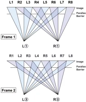
Fig. 1 Time-division duplexing parallax barrier.
multiplexing provides a practical solution to show full dis- play resolution to both eyes [2]. Figure 1 shows an example of time-division duplexing parallax barrier, where frame 1 shows half of the resolution and frame 2 shows the other half. The adjacent two frames switch between each other at a refresh rate of 120 Hz to achieve flickerless autostere- oscopy.
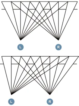
Head-tracking is a helpful way to solve the viewing zone issue [3], [4]. As shown in Fig. 2, sweet spots can be increased by tracking the position of the viewer and adjust- ing the barrier pattern accordingly, where the viewing zone is widened indirectly. Sweet spots at different viewing dis- tances can also be created by adjusting the aperture width.
However, since the range of each sweet spot is narrow, both high precision and short respond time is required for the in- volved tracking device, which may make the whole system cost more. Furthermore, barriers made of LCDs can only be adjusted discretely as a minimum unit of 1 pixel exists.
Therefore, some of the areas may not be covered by any of the available sweet spots and providing perfectly continuous viewing zone is considered difficult.
In this paper, we introduce an autostereoscopy system based on time-division quadplexing parallax barrier, which is able to show full display resolution per view and hold continuous viewing zone at the same time.
Copyright c⃝2014 The Institute of Electronics, Information and Communication Engineers
Fig. 2 Parallax barrier with head-tracking involved.
Fig. 3 4-view parallax barrier.
2. Method
2.1 Time-Division Quadplexing
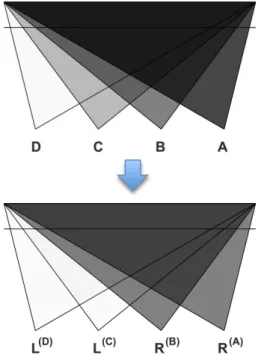
In parallax barrier systems, aperture ratio determines the number of viewpoints. By setting the aperture ratio to one quarter, we create a 4-view parallax barrier system, where one quarter of the display resolution is achieved at each viewpoint (See Fig. 3).
Then with time-division quadplexing applied, full res- olution per view can be achieved, where fast switching four frames act as one (See Fig. 4).
As shown in Fig. 5, we apply the right-eye image of a stereo pair to the two viewpoints on the right side and the left-eye image to the two viewpoints on the left side, obtain- ing four viewpoints aligned as “Left–Left–Right–Right” (L–
L–R–R). The system turns to a stereoscopic one that shows 2-view, where “L–L” is the viewing zone of the left-eye im- age and “R–R” is that of the right-eye image [5], [6].
Fig. 4 Time-division quadplexing parallax barrier.
2.2 Analysis on Viewing Zone
Viewing zone of an autostereoscopic system is the area where the viewer can achieve correct stereoscopy without crosstalk, which means both the left eye and right eye should not see any pixels of the contrary view. For instance, the viewing zone for the left eye should be the area where all the “R” pixels cannot be seen (See Fig. 6). The borderlines that follow the above rule are marked with dotted lines, and
Fig. 5 Wide viewing zone achieved with the “L–L–R–R” alignment.
the viewing zone for each eye is then determined by the bold solid lines. Meanwhile, the viewing zone for correct stere- oscopy is much narrower since it is necessary for both eyes to stay in respective viewing zone. Slight adjustment on aperture width and panel interval is required to achieve the widest possible viewing zone at an appropriate viewing dis- tance. It is plain to see that when the adjacent viewpoint in- terval (for example, the interval between viewpoint L(C)and R(B)in Fig. 6) is set to 32.5 mm (half the value of common human interpupillary distance), the widest width of view- ing zone can be achieved at the designed viewing distance, which will also be 32.5 mm. Then the complete viewing zone for stereoscopy turns out to be a diamond shape, as shown with the two filled parts in Fig. 6.
Then we add head-tracking into the system. By ad- justing the offset and size of the apertures according to the viewer’s position, viewing zone in both crosswise and depth direction can be extended. In the current method, one sweet spot without tracking covers much wider space than in that of the conventional methods, so even tracking devices with relatively low precision and long respond time will be enough to provide continuous viewing zone.
2.3 Prototype
We construct a prototype based on the proposed method with two LCD panels, one for the image panel and the other for the barrier panel. The detailed specifications are listed below.
• LCD: BenQ XL2410T (120 Hz, 24-inch, full HD)
• GPU: AMD FirePro Series with Eyefinity supported to make multiple displays strictly synchronized at a high refresh rate.
Fig. 6 Viewing zone of the proposed system.
• Interface: DisplayPort Version 1.2 to ensure the band- width for two full HD images at 120 Hz.
• Head-tracking: Microsoft Kinect for Windows with of- ficial SDK.
The prototype successfully shows full panel resolution to each viewpoint and provides continuous viewing zone with head-tracking involved, while flickers and moire pat- terns turn to be easily notable.
As mentioned in the introduction chapter, time-division duplexing requires a high refresh rate of 120 Hz to show flickerless stereoscopy. Therefore, in a time-division quad- plexing situation, 240 Hz displays, which are hardly avail- able at this moment, are necessary to provide stable images.
As a result, flickers stand out in this prototype. On the other hand, moire patterns occur since two identical LCD pan- els are overlaid with a very short distance apart in this sys- tem, where the identical alignments of the RGB color filters on the two LCD panels create the visually evident superim- posed patterns.
To provide high quality stereoscopy, solutions for flick- ers and moire patterns have to be considered.
3. Improvement
3.1 Solution for Moire Patterns
RGB color filters on most of the LCD panels are aligned in the horizontal direction and create vertical moire patterns when overlaid. The vertical moire patterns can be simply re- moved by inserting a horizontal diffuser between the image panel and the barrier panel, while the vertical parallax im- age patterns on the back panel will be destroyed at the same time.
We interchange the positions of the two panels and ro- tate them by 90◦while keeping the parallax patterns vertical, so that the direction of the moire patterns will be perpendic- ular to that of the parallax patterns. Then by inserting a ver- tical diffuser between the two panels, moire patterns can be removed while the vertical parallax barrier patterns on the
Fig. 7 Structure of the improved system.
back panel are not influenced at all [7]. The structure of the improved system is shown in Fig. 7.
3.2 1-Pixel Aperture
Humans perceive flickers when changes in luminance take place either spatially or temporally at certain levels. In our prototype, luminance changes in certain widths (the aper- ture width) at 30 Hz (time-division quadplexing at 120 Hz), which leads flickers to occur. Since it is difficult to raise the refresh rate at this moment, we introduce 1-pixel aperture to reduce flickers. By narrowing the aperture width to 1-pixel level (about 0.27 mm wide in a 24-inch/full HD situation), even though the temporal rate of the changes in luminance keeps at 120 Hz, the spatial size of them becomes so tiny that the viewer from a common viewing distance will not be able to perceive.
We carry out a simple test to figure out the flicker level of the system with 1-pixel aperture applied. 10 Subjects in their twenties (9 males and 1 female) are ordered to watch a stereo photo (Tsukuba stereo pair) shown on the improved system while sitting still and then to choose from the fol- lowing descriptions:
(1) Strong flickers perceived all the time;
(2) Weak flickers perceived all the time;
(3) Weak flickers perceived most of the time, with some strong ones noticed at times;
(4) No any flickers perceived most of the time, with some strong ones noticed at times;
(5) No any flickers perceived most of the time, with some weak ones noticed at times;
(6) No any flickers perceived all the time.
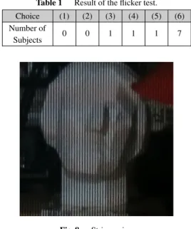
The result is shown in Table 1.
Seven of the ten subjects do not perceive any flickers at all, while the rest 3 of them having various flicker experi- ences. Since 9 of the 10 subjects perceives no flickers or few flickers throughout the test, we consider it is fair enough to tell that for most people the current system shows comfort- ably stable stereoscopy. Meanwhile, we figure out that this 1-pixel aperture system suffers from another kind of noise, which leads to the intermittent flicker experiences in the test.
Table 1 Result of the flicker test.
Choice (1) (2) (3) (4) (5) (6)
Number of
0 0 1 1 1 7
Subjects
Fig. 8 Stripe noise.
As shown in Fig. 8, narrow stripes with uniform width are noted when making a blink or a saccade in the improved system. Similar to color breaking, this type of noise is due to a lack of refresh rate. Human beings are sensitive to 60 Hz luminance changes, especially when making a blink or a saccade. As the proposed system runs time-division quadplexing at 120 Hz, the pattern from two adjacent frames stands out. Since the parallax barrier pattern is aligned as
“white-black-black-black” (WKKK) and switches by one phase every one frame, the pattern from two frames turns to “WWKK,” which leads to the uniform stripe noise. The solution for stripe noise will be introduced in the next sec- tion.
Although flickers are successfully reduced by the 1- pixel aperture method, a negative effect on the viewing zone occurs at the same time. Like most of the parallax barrier systems, the width of the parallax barrier patterns should be slightly different from that of the parallax image patterns in ours, so that the light rays towards the viewer can perfectly converge at one point (see Fig. 7). However, it is impossible to follow if we try to execute the 1-pixel method described above when two identical LCD panels are used. So we ac- tually set both the parallax barrier patterns and parallax im- age patterns to 1 pixel wide and involve extra correction on rendering. In detail, periodical 1-pixel phase shift of paral- lax barrier pattern is applied to ensure that the light direc- tion of every image pixel is shown as correctly as possible.
Although the system still keeps providing continuous view- ing zone due to the wide permissible range of the proposed method, the width of each sweet spot will be greatly reduced by such 1-pixel adjustments, where all of the apertures are neither perfectly placed nor sized as the method requires. In other words, the limitation on the head motion speed caused by the head-tracking latency will be more severe.
A motion speed test is done to find how fast a viewer is allowed to move in the crosswise direction with no crosstalk noted. Ten subjects (9 males and 1 female in their twen-
Table 2 Result of the motion speed test.
Max Speed
Range 50~59 60~69 70~79 80~
(mm/s) Number of
4 2 3 1
Subjects
ties) are ordered to move their heads from left to right and describe the crosstalk experiences, while an ideal viewing distance is always kept. A set of two markers placed 15 cm away from each other helps us to tell the motion speed by measuring the time the viewer uses to pass from one marker to the other. We repeat the test on the same subject several times until the borderline of crosstalk perception is found.
The distribution of the maximum motion speed values with- out crosstalk is shown in Table 2.
The motion freedom provided by the current system is much less than that of the theoretically ideal one, while it still is considered practical for ordinary applications without frequent head motions.
3.3 Active Anaglyph Parallax Barrier
For human eyes, time-division multiplexing anaglyph is found to show weaker flickers than the conventional time- division multiplexing method does at a low refresh rate, especially when using green and magenta as the anaglyph pair [8]–[10]. It is plain to see that anaglyph pairs hold closer luminance values than black and white do. Fur- thermore, psychophysically, green component contributes to about 59% of the luminance while red and blue shows 30%
and 11% respectively, which means green and magenta have the closest luminance values among all the anaglyph pairs.
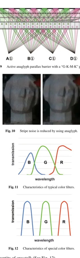
To reduce stripe noise, we apply green and magenta anaglyph to our time-division quadplexing parallax barrier and call it active anaglyph parallax barrier for short. The parallax barrier patterns and the parallax image patterns are created based on those in Fig. 7, where the “white-black- black-black” (WKKK) pattern is replaced by the “green- black-magenta-black” (GKMK) pattern, as shown in Fig. 9.
Then the pattern from two frames turns to “GGMM”, which shows much more uniform luminance when compared to the
“WWKK” pattern, and the stripe noise drops greatly (See Fig. 10).
However, it is widely known that anaglyph brings extra crosstalk due to the colors filters on LCDs. Default RGB color filters on LCD panels share certain ranges of wave- length and fail to separate anaglyph colors completely (See Fig. 11). Since a green filter shares wavelength with both red and blue, larger quantity of crosstalk are perceived when using green and magenta as the anaglyph pair. Although red and cyan (or blue and yellow) may show less crosstalk as the shared range of wavelength is relatively narrow, a certain color tone due to the narrow range makes it easily notable as well.
Replacing the default color filters on the LCD panels by special ones holding narrow bandwidths may help to lower
Fig. 9 Active anaglyph parallax barrier with a “G-K-M-K” pattern.
Fig. 10 Stripe noise is reduced by using anaglyph.
Fig. 11 Characteristics of typical color filters.
Fig. 12 Characteristics of special color filters.
the quantity of crosstalk (See Fig. 12).
4. Comparative Experiment
We implement the following improvements to the prototype:
(1) 1-pixel aperture and moire solution;
(2) Active anaglyph;
Fig. 13 Comparative experiment result.
(3) Extra color filters with narrow bandwidths.
Alphabet images “A” and “B” are used as the stereo pair to figure out how our methods work in the following three conditions:
I Using only (1);
II Using (1) and (2);
III Using (1), (2) and (3).
The results are shown in Fig. 13. In all conditions, clear and stable images are achieved without any striking flickers or moire patterns. The highest image quality is ob- tained under condition I with hardly notable crosstalk, while stripe noise occurs. Under condition II, stripe noise drops greatly while crosstalk stands out. Although both crosstalk and stripe noise are controlled to low level under condition III, the images become dark due to the additional filter.
From the results, it is fair to say that a trade-off be- tween stripe noise and crosstalk exists. Extra color filters holding narrow bandwidths provide a possible solution for both issues while stronger backlight should be taken into consideration.
5. Conclusion
We have created a high quality autostereoscopy system based on time-division quadplexing parallax barrier, which shows full display resolution per view and holds wide view- ing zone. Although 240 Hz displays are required to realize this system without flickers, we have come up with practi- cal solutions to achieve acceptable image quality at 120 Hz by introducing 1-pixel aperture parallax barrier combined
with a vertical diffuser and periodical phase shifts, while the stripe noise can be reduced with time-division active anaglyph. However, further work is needed to find a better solution for the trade-offbetween stripe noise and crosstalk.
Acknowledgments
This research is partially supported by the Grant-in-Aid for Scientific Research, MEXT, Japan, Grant number:
25280070. We thank Ken Okada for his assistance to com- plete the experiments.
References
[1] K. Perlin, S. Paxia, and J. S. Kollin, “An autostereoscopic display,”
Proc. 27th Annual Conf. on Computer Graphics and Interactive Techniques, pp.319–326, 2000.
[2] H. J. Lee, H. Nam, J. D. Lee, H. W. Jang, M. S. Song, B. S. Kim, J. S.
Gu, C. Y. Park, and K. H. Choi, “A high resolution autostereoscopic display employing a time division parallax barrier,” SID Symp. Dig.
Tech., vol.37, pp.81–84, 2006.
[3] S.-Y. Yi, H.-B. Chae, and S.-H. Lee, “Moving parallax barrier de- sign for eye-tracking auto-stereoscopic displays,” Proc. 3DTV Conf.
2008, pp.165–168, 2008.
[4] J.-E. Gaudreau, “Full-resolution autostereoscopic display with all- electronic tracking system,” Proc. SPIE, vol.8288, 82881Z, 2012.
[5] Q. Zhang and H. Kakeya, “An autostereoscopic display system with four viewpoints in full resolution using active anaglyph parallax bar- rier,” Proc. SPIE, vol.8648, 86481R, 2013.
[6] Y. Yang, A. Higashi, T. Uehara, T. Kasai, and T. Koito, “A wide- view high resolution 3D display using real-time rendering relating to viewer position,” SID Symp. Dig. Tech., vol.44, pp.78–80, 2013.
[7] Q. Zhang and H. Kakeya, “A time-division multiplexing parallax barrier system with wider viewing zone,” IDW ’13 Proc., pp.1024–
1027, 2013.
[8] J. Kim, Y. Kim, J. Hong, G. Park, K. Hong, S.-W. Min, and B. Lee,
“A full-color anaglyph three-dimensional display system using ac- tive shutter glasses,” J. Inf. Display, vol.12, no.1, pp.37–41, 2011.
[9] H. Kakeya and H. Kodaira, “Full color stereoscopy with little flicker at low refresh rate by time-division multiplexing anaglyph,” Proc.
SPIE, vol.8288, 82880K, 2012.
[10] Q. Zhang and H. Kakeya, “Quadruple time-division multiplexing anaglyph,” Proc. 3DSA2012, pp.171–174, 2012.
Qu Zhang received the B.S. and M.S. de- grees in Information Engineering from Zhejiang University in 2010 and University of Tsukuba in 2014, respectively.
Hideki Kakeya received a doctoral degree in engineering in 1998 from the University of Tokyo. He worked for the Communications Re- search Laboratory from 1998 to 2001. Since 2001, he has been a faculty member of Univer- sity of Tsukuba.