Effective
Three-Dimensional
Finite
Element
Analy
Optimum
Design
of
Composite
Patch
for
Repairing
Structural
Panels
sis
and
Hideki
SEKINE
and
Daisuke
AOKI
Depatrtment
of
Aeronautics
anAoba-yama
Old
Spa
£eEngineering,
[[bhoku
University,
,
Sendai
980-8579,
Japan
Composite
patch
repairof
aircraft
structural
panels
has
recentlyreceived
wide
attention.
When
this
repairtechnique
is
applied
to
the
aircraft
structuralpanels,
it
is
imperative
to
design
composite
patches
which are reliableenough
to
operate
in
severe
environmental
conditions.
In
designing
compositepatches,
the
accuratestress
fields
in
the
repairedstructural
panels
and
the
bonded
compositepatches
should
be
analyzed
since
highly
complicatedthree-dimensional
stress
fields
aredeveloped.
Tb
obtainthe
accurate
stress
fields
in
repaired structuralpanels
and
bonded
compositepatches,
usuallythe
conventional
threedimensional
finite
elementmethod
is
used.
However,
the
conventional
three-dimensional
finite
element
methodinvolves
witha
long
computationaltime
for
iterative
stress
analysis.In
this
paper,
we
develop
an
effective
threGdimensional
finite
elementmethod
based
onthe
concept ofdomain
decomposition
with
independent
interfaces.
Using
this
method,
we
carry
out severalparaJnetric
studies
to
examinethe
efiect
of
patch
shape and size onthe
stress
fields
in
a repaired structural
panel
and
bonded
compositepatches.
The
methodis
also usedto
determine
the
optimum
patch
shapeand
size
so
as
to
endure
maximumtensile
applied stress
by
a
mathematical
programming,
Kley
illordS:
3D-FEM
analysis,
Domain
craft
structural
panel,
Optimum
designdecomposition,
Composite
patch
repair,
1
Introduction
Recently,
compositepatch
repairof
aircraft
struc-tural
panels
has
received
wide attention,The
repair
using composite
patches
causes
less
damage
to
the
repaired
structural
panels
than
that
of repairusing
me
chanical
joints,
In
addition,
the
compositepatches
are
comparatively
lightweight
due
to
their
higher
specific stiffhess andstrength.
In
the
damaged
structural
panels,
a
circularhole
is
made
by
cutting
the
damaged
portion,
Se
far,
afew
studies of compositepatch
repair
of structuralpanels
with
a
circularhole
have
been
carried
out
by
someinvestigators(i)-(5).
Chue
andWang(2),
andChue
et
al,(3)
determined
the
optimum
ply
orientation ofthe
composite
patch
by
parametric
calculations using fi-nite element analysis.Further,
Soutis
et al.(4)deter-mined
the
optimum
overlaplengt]h
for
adhesion
by
a shearlag
stressanalysis.
However,
the
study ofop-timum
patch
shape
and sizehas
still
remained
to
be
made.
In
designing
composite
patches,
the
accurate stressfields
in
the
repaired
structural
panels
andthe
bonded
compositepatches
should
be
analyzed
sincea
highly
complicatedthree-dimensional
stress
field
is
developed,
The
conventional
threedimensional
finite
element
methodto
calculatethese
stressfields
involves
with
a
long
computationaltime
for
iterative
stressanalysis.
In
this
paper,
wedevelop
aneffective
three
dimensional
finite
element
methodbased
on
the
con-cept of
domain
decomposition
withindependent
in-terfaces.
Then,
the
finite
elementanalysis
fbr
subdo-mains cambe
carriedout
separately.
This
is
particu-larly
very usefu1in
the
optimumdesign
of
compositepatches
whereonly
the
shape
ofthe
patch
is
neededto
be
changedin
optimizationprocess
keeping
the
otherpordons
ofarepairedstructural
panel
unchanged.
car-NII-Electronic Library Service
ried
out
to
examine
the
effect
ofpatch
shape and size onthe
stressfields
in
a
repairedstructural
panel
and
bonded
compositepatches,
andthe
optimum
design
of a composite
patch
by
a mathematicalprogramming
is
fbllowed.
2
EffectiveThree-DimensionalFiniteElement
Method
Based
on
the
Dornain
Decomposition
So
far,
several
finite
element
methods(6)-(iO)
based
on
the
concept
of
domain
decomposition
have
been
proposed.
Among
these
methods,
the
FETI
method(iO)
is
advantageous asit
can analyzethe
prob-lems
withhundreds
of
thousand
degrees
of
freedorn.
In
this
method,
the
continuity
of
displacement
among
the
subdomains
is
satisfied
by
making
use
of
Lagrange
multipliers.
However,
using
of
Lagrange
multipliers,the
formulation
is
complicatedto
solvethe
floating
problems.
Thus,
it
is
not easyto
develop
the
com-puter
prograin
of
this
methodbased
on
the
conven-tional
finite
element
method.
This
diMculty
urges
to
introduce
a
method
whose
computer
program
can
be
easily
developed
based
on
the
conventionalfinite
ele-ment
method.
In
this
paper,
wedevelop
an effectivethree-dimensional
finite
element methodbased
on
the
con-cept of
domain
decomposition
withindependent
in-terfaces,
The
penalty
function
method(ii)
is
used
to
account
for
the
continuity
of
displacement
aJnong
the
subdomains.
As
to
the
independent
interfa
£es,
two-dimensional
ones
are
introduced
to
analyze athree-dimensional
problem,
Furthermore,
to
enablethe
effective
analysisof
a
decomposed
body,
a
special
pr}
cedure
is
introduced
to
analyze
the
subdomains
sepa-rately.
A
schematic view ofdornain
decomposition
is
shownin
Fig.1
which exhibits anindependent
inter-face
£ i and onlytwo
subdomains9i
and
st2
in
IVa
subdomains.
The
subdomainsare
connected
through
the
independent
interface
in
which
the
constraints ofthe
continuity
of
displacement
amongthe
subdomainsare
imposed
by
the
penalty
function
method.The
po-tential
energyll
ofthe
decomposed
body
including
the
independent
interface
canbe
given
by
"-
£
.,
Hgt
+Sic
fllll,
(v
-
u,)2dA
(1)
llt V U2
Fig,
1
Decomposed
body
where
k
is
the
penalty
parameter,
uiis
the
disp)ace-ment
vector
of
the
subdomain
sti,
and
v
is
the
dis-placement
vector
of
the
independent
interface.
In
orderto
develop
athreedimensional
finite
el-ement method
based
onthe
domain
decomposition,
it
is
first
necessaryto
discritize
Eq.(1),
which canbe
performed
by
substitutingthe
fo11owing
relationsinto
Eq.(1).
ui=Niqi,
(2)
v=Tqi.
(3)
In
Eqs,(2)
and(3),
qi
andqi
arethe
nodaldisplace-ment vectors of
the
subdomain9i
andthe
indepen-dent
interface
Zi,
respectively;Ni
andT
arethe
shape
function
matrices.Further,
wehaye
aiso
the
foilowing
relation:
6filq,,q,
==O(i=1i'''ilVa)'
(4)
Now,
the
equilibrium
equations canbe
obtainedby
substituting
the
discretized
form
ofEq.(1)
into
Eq.(4)
as
follows:Kl
O.,,
O
-PII
O
K2
...
O
-PI2
tt
t
t
ttt
tt-
t
o
O
O
KN,
-PIN,
-pT,-PF,...-PF..
Ki
matrix
Ki
is
always
symmetric
qlop:'dqNdql
fifp
fyo
(5)
where
Ki
matrixas-sociated
dependent
inter-face,
couplingterm
between
dependent
inter-fhce
andGIn
Eq,(5),
the
stiffuess
and
positive
definite.
obtainedbya
simple
direct
solver even whichhas
no
boundary
floating
problerns
are encountered
penalty
function
method.
Algebraic
manipulation
of
Eq.(5)
yields
(Ki
r
IS.
i,
PF,K,-
iPit
)
qi
=£
.,
P7,K,-
ifl
(6)
qi
=K,i iPiiqi+K,,
i&(i
==1,...,Nh).
(7)
When
the
inverse
matricesof
each
subdomain
are
calculated and substituted
into
Eq,(6),
we
obtain
the
nodal
displacement
vector
qi
of
the
independent
inter-face,
Next,
the
nodal
displacement
vectorqi
is
sub-stituted
into
Eq,(7)
to
obtainthe
nodaldisplacement
vectorqi
of each subdomain.Here,
it
is
notedthat
the
analysis
ofthe
wholedecomposed
body
can
be
carried
out
by
analyzingthe
subdomains
separately,
Thus,
for
the
model
in
whichthe
mechanicalcharacteris-tics
andgeometry
in
some subdomainsare
changedin
-
691
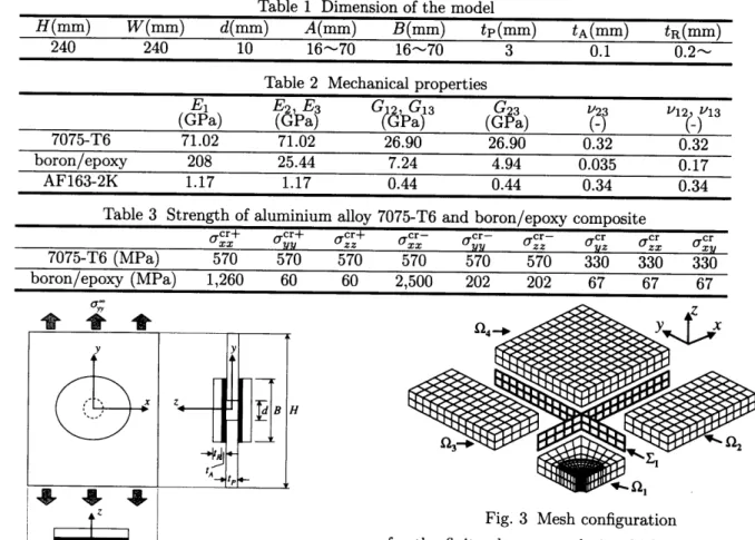
[[hble
1Dimension
of
the
model
H(mm)PV(mm)d(mm)A(mm)B(mm)tp(mm)tA(MM)tR(MM)
240
240
10
16t--7016・v70
3
O.1
O.2t-.
[[bble
2Mechanical
properties
El(GPa)
fa'pEa9
%
£
S3
C23(GPa)
?s
7075-T6
Vl?)V13
71.02
71,02
26.90
26,90
O.32
O.32
boronlepoxy
208
25.44
7,24
4.94
O.035
O,17
AF163-2K
L17
1.17
O.44
O.44
O,34
O.34
Table
3
Strength
ofaluminium
alloy7075-T6
andboronlepoxy
composite
cr+o x=aCr570 cra zz cr-a x=aCrr cr-azz
7075-T6
(MPa)
aCr.
cra ==a:r570
570570570570330330330
boron/epoxy
(MPa)1,26060
602,500202202676767
twc{;fey
x H1I/I$gg:/fx
AWFig.
2
Model
of
bonded
compositepatches
and
repaired
structuralpanel
each
iteration,
it
is
necessary
to
calculate
the
inverse
matrices
ofall
the
subdomains
at
the
first
iteration.
After
that,
the
inverse
matrices
of onlythe
subdo-mains
whose
mechanicalcharacterictics
andgeometry
are
changed
are necessaryto
calculate
in
the
next it-erations,This
feature
ofthe
present
method makesit
more effectivethan
the
conventionalfinite
elementmethod
in
the
optimizationprocess.
3
NumericalExamples
3.1
Model
ofbonded
composite
patches
and
paired
structural
panels
A
model of aircraft structuralpanels
with
a
circu-lar
hole
repaired withtwo
elliptic
compositepatches
bonded
to
each side ofthe
panel
is
shownin
Fig.2,
The
major andthe
minor
axes
ofthe
ellipticcompos-ite
patches
are
A
andB,
respectively.The
thickness
of
the
panel,
the
patch
andthe
adhesiveare
tp,
tR
andtA,
respectively,The
diameter
of
the
circularhole
of
the
panel
is
d.
The
panel
is
subjected
to
auni-form
applied
tensile
stress ayeey.The
deflection
of
the
loading
edges
is
constrained
to
be
zero.
Due
to
sym-metry,
only
oneeigth ofthe
model canbe
considered
S)3'
94-
Y"<E.ix
nl
snl
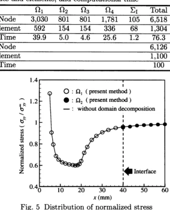
Fig.
3
Mesh
configurationfor
the
finite
element
analysiswhich
is
decomposed
into
four
subdomainsas
shownin
Fig.3,
This
figure
also
shows
the
mesh
configuration
used
in
the
present
analysis,
The
subdomain9i
representsthe
portion
of
the
panel
which
includes
oneforth
ofthe
patch.
In
the
finite
element
analysis,20-noded
isoparametric
threedimensional
brick
elements
areused
in
the
panel
and
the
patch.
The
adhesive
is
assumedto
consist
oflinear
spring
elements.The
mesh configurationused
in
the
conventional
finite
element
methodis
also
the
same
except
that
the
indepenedent
interface
has
no
existence,
i,e,
the
subdomainsare
directly
connected.The
variousdimensions
ofthe
model
are
shownin
[Ibble
1.
The
panel
and
adhesive
materialsare,
re-spectively,
aluminium
alloy
7075-T6
andAF163-2K.
The
patch
is
made of aboron/epoxy
compositein
which
fibers
areparallel
to
the
y-axis.
The
mechan-ical
properties
ofthese
materials
are shownin
[fable
2,
Also,
the
strengthof
an
aluminium
alloy
7075-T6
and
a
boron/epoxy
compositeis
shownin
Table
3.
3.2
Vlerificationofefficiencyandaccuracy
A
comparison
of
the
number of nodesand
el-ements, and
computational
time
requiredby
the
present
method andthe
conventional
fininte
eiement
method
is
shown
in
Table
4.
The
number ofnodes
in
each subdomainfor
the
present
method
is
smallerthan
half
of
that
for
the
conventional
finite
element
method.
The
computationaltime
is
also
shorterfor
NII-Electronic Library Service
[lable
4Comparison
ofthe
number
of
nodes
and
elements,
and
computationaltime
Method
Domain
decomposition
91st2st3st4
£I[[btalPresent
methodApplied
Node3,0308018011,7811056,518
Element592154154336681,304
Time39,95.04.625,61.276.3
Conventional
FEM
Not
appliedNode
6,126
Element
1,100
Time
100
1.02
7,eifgsg
O.97"oEE
O・9
log,e(kIE)
Fig.
4
Relationship
between
the
normalized
penalty
parameter
and
the
normalized
stress
ference
canbe
observedfrom
the
table,
Compared
to
the
conventionalfinite
element method,the
computa=tional
time
for
the
present
methodis
about80%
whenal1
the
subdomains are considered and about40%
when
only
the
subdomain
sti
and
the
independent
in-terface
Zi
which are calculatediteratively
in
the
op-timum
design
of a compositepatch
are considered.Thus,
it
is
realizedthat
the
eMciencyof
the
present
method
is
much
better
than
that
of
the
conventional
finite
element
method.
It
should
be
mentioned
that
this
difference
occurs whenthe
modifiedCholesky
de
composition combined with
the
band
methodis
usedfor
calculation.The
effect
of
the
normalized
penalty
parameter(icIE)
on
the
normalized
stress(ayylagy)
is
shown
in
Fig.4.
The
penalty
parameter
k
is
normal-ized
by
the
Ybung's
modulusE
of
aluminum
alloy
7075-T6.
The
stress
at
the
edge
of
the
circular
hole
ayy(x=d12,
y=e,
x=O)
is
normalized
by
the
stress
crgy(x=:d12,
y=O,
z=O) obtainedby
the
conventionalfinite
element method,In
this
figure,
the
open circlesrepresent
the
results ofthe
present
method
and
the
solid
line
representsthe
results ofthe
conventionalfinite
element method.In
the
numericalexamples
considered
from
here
onward,
the
calculations
are
carried
out
by
using
the
penalty
parameter
corre-spendingto
the
value5
onthe
horizontal
axis of1.4
t's
1.2ifs"1gs
O.8xk-g
o.6z
O.4
O
10
20
30
40
SO
60
x(rnrn)
Fig.
5
Distribution
of normalized stress(ayylayOOy)
along
the
x-axis
(y=O,z=O)
Fig.4.
Shown
in
Fig.5
is
the
normalized stressdistribu-tion
alongthe
x-axis,In
this
figure,
the
open and close circles, respectively, representthe
normalized stressdistributions
in
the
subdomainssti
andst2.
The
solidline
showsthe
normalized stressdistribution
obtained
by
the
conventional
finite
element methed.It
is
notedthat
the
difference
between
the
results obtainedby
the
present
andthe
conventionalfinite
element methodre-mains within
1%.
This
means
that
the
accuracy
of
the
present
method
is
the
same
as
that
of
the
conventional
finite
element
method.
3.3
Preliminaryanalysis
As
apreliminary
analysisfor
the
optimum
design
of
a
composite
patch,
several
parametric
studies
are
carried
out
to
examine
the
effect
of
the
major axisA,
the
minoraxis
B
aridthe
thickness
tR
ofthe
elliptic compositepatch
onthe
stressfields.
The
relationship
between
the
major axisA
aridthe
maximum normalized stress(ayMyaXlaCr)is
shownin
Fig,6(a),
where aCris
the
strength ofthe
aluminium alloy7075-T6.
The
figure
shows
that
the
ma)cimum
normalised
stress
gradually
decreases
as
the
major
axis
A
inc;eases.
The
relationshipbetween
the
minoraxis
B
andthe
maximum
normalized
stress(ayMya'`laC')
is
shown
in
Fig.6(b).
In
this
figure,
the
maximumnormalized
stressis
a concavefunction
ofB.
This
is
because
the
shear stressdeveloped
in
the
elliptic
com-posite
patch
rises
with
the
minoraxis
B
whichin
turn
-
693
.Ag
onk)g
o,6stheaB o.6.NaF2 o,sssE'Res o.sE 20 30 40SO
60
A(mm)
(a)
Majer
axisA{tR=O.4mm)
Fig.
6
Effect
of
shape and sizea,OO,==245(MPa) 1.4
ig
l.3oe 12a>: IJST,
ts-
OJbv o.6s$euBo.6.NreE2
o.ssi.E:O.5E
gF
g・
go=E=ES5
O.95O.9O.8SO.BOJSO.7O.6SO,6o.ss20
30 40 SO 60B(rnm)
(b)
Minor
aJcisB(tR=O.4mm)
of composite
patches
on
the
maximum normalk ℃
sgi.gtsE
O.9 20 30 40 SO 60A
(mm)
(a)
Major
axisA<tR=O.4mm)
Fig.7
Relationship
offracture
cona,co,
=245(MPa)1.41.31.21.1
O.9D.8O.7
20 30 40
SO
60
B(mm)
(b)
Minor
axisB(tR=O,4mm)
dition
of
composite
patches
withproduces
alarger
stressin
the
panel,
The
relationshipbetween
the
thickness
tR
andthe
maximum
normal-ized
stress(oyMyaX!aCr)
is
shownin
Fig.6(c).
It
is
seen
from
this
figure
that
the
dependency
ofthe
thickness
tR
onthe
maximumnormalized
stress
is
significant.The
fracture
conditionfor
a
composite
accordingto
Hofiman
criterion
can
be
writtenas
F
=Ci
(ayy
-
a.x)2+
C2
(a..
-
axx)2+
Cb
(a..
-
ayy)2+
(]4a.x
+
Csayy+
Cba..
+
C7a,2.
+
Cba.2.
+
Cb
ag,(s)
wherethe
coeficientsCi
to
Cb
are
obtainedfrom
the
strength ofthe
cemposite.A
composite
willfracture
whenthe
valueof
F
exceeds
unity.The
relationship
between
the
majoraxis
A
and
the
maximum value ofF
in
the
ellipticcomposite
patch
is
shownin
Fig,7(a).
This
figure
showsthat
the
maximum value ofF
grad-ually
de
¢reasesas
the
major axisA
increases.
The
relationship
between
the
minor
axis
B
andthe
max-imum
valueof
F
in
the
elliptic compositepatch
is
shownin
Fig.7(b).
In
this
figure,
the
maximum valueof
F
is
a
concavefunction
of
B.
This
is
because
the
shear
and
peel
stresses
become
larger
at
the
edge
ofthe
ellipticcomposite
patch
due
to
the
bending
effect asthe
minor axisB
becomes
larger,
The
relationship].B l.64ts
1.4s->1.2a=El.-ajE
o,se,6
O O.2 e.4
O,6
O.8 1 ]2tR
(mm)
(c)
Thickness
tR
ized
stress(ayrnyaxlaCr)
fbr
O O,2 O.4 O.6
O,8
1 1,2tR
(mm)
(c)
Thickness
tR
the
parameters
A,
B
andtR
for
between
the
thickness
tR
andthe
maximum
value ofF
in
the
elliptic
compositepatch
is
shown
in
Fig.7(c),
This
figure
showsthat
the
ma)[imum valueof
F
grad-ually
increases
asthe
thickness
tR
increases.
F)rom
the
above results,it
is
realized
that
the
shape
and
size
ofthe
elliptic compositepatch
have
great
effectson
the
stress
fields
in
the
repairedstruc-tural
panel
and
the
bonded
compositepatches.
3.4
Shapeoptimizationofacompositepatch
3.4.1
Formulation
In
this
article, we outlinethe
design
procedure
for
obtaining
the
optimumpatch
shape and size
so
that
it
can
endure maximumten-sile
applied stress.The
parameter
Ik
controlingthe
size
of
the
elliptic compositepatch
is
introduced
as requiredin
formulating
the
optimizationproblem
asfo11ows:
Maximize:
aco yySubjectto:
F<1
(9)
ayMyaxlaCr
<
1
ABtR
=Iii{
where
the
design
variables
areA,
B,
tR
andayOOy,
In
this
shape
optimization,
the
side constraints ofthe
design
variablesA,
B
and
tR
as16(mm)
-<
A,
B
S
70(mm)
and
tR
)
O.2(mm).
The
first
constraint
ofthe
NII-Electronic Library Service
340
330A
320esS
310L-/
3008,M'
290g,:
280S
27o
260
250
240
O
100
200
300
Vit
(mm3)
Fig.
8
Ma)cimum
applied
tensile
against
the
parameter
VR
400500
Stress
ayOoyfracture.
The
second constraint restrictsthe
panel
from
failure
by
overloading,the
third
constraintcon-trols
the
size ofthe
elliptic compositepatch.
The
op-timization
problem
is
solved
by
using
an
optimization
program
ADS
in
which
the
method
of
feasible
direc-tions
is
used
as
an
optimizer
while
the
polynomial
interpolation
is
used as a one-dimensional search.3.4.2
Results
anddiscussion
The
relationshipbetween
the
maximum appliedtensile
stress
ay'Oyand
the
parameter
Vk
is
shown
graphically
in
Fig.8.
This
figure
shows
that
the
gradient
of
maximum
ayOOy
against
iik
decreases
as
the
parameter
ltk
increases.
This
indicates
that
too
large
patch
is
not
effective
to
repair
the
panel
with
a
circular
hole.
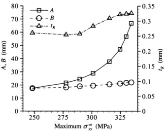
Figure
9
showsthe
relationship ofthe
parameters
A,
B
and
tR
withthe
ma)cimum
applied
tensile
stress
ay"Cy,
Flrom
this
figure,
it
is
seen
that
the
majoraxis
A
increases
whilethe
minor axisB
almost remainsthe
same asthe
maximum appliedtensile
stress ayOeyincreases.
This
is
because
the
maximum stressdevel-oped
in
the
panel
andthe
maximum valueof
F
in
the
composite
patch
are
1arge
whenthe
minor axisB
is
too
large
ortoo
small,The
thickness
tR
remainscon-stant up
to
a certain value ofthe
ma)[imum appliedtensile
stress after whichit
increases
asthe
ma)cimum appliedtensile
stressincreases,
It
is
observed
that
the
optimum
patch
shape
is
circular
when
the
maximum
applied
tensile
stress
is
smaller and elliptic with
the
minor axis alongthe
load-ing
direction
whenthe
maximum
applied
tensile
stress
is
higher.
4
Conclusions
In
this
paper,
we
have
developed
an effectivethree-dimensional
finite
element methodbased
onthe
concept of
domain
decomposition
withindependent
interfaces,
The
method
is
applied
to
carry out astress807060AE
sovco
302010
O.35O,3025
o.2
go.is
lny
O・1O.05
o
o
250
275
300
325
Maxlmum
oyco..
(MPa)
Fig.
9
Relationship
of
the
parameters
A,
B
and
tR
withthe
maximum
applied
sile
stress
aO
yy
analysis
of
a
repaired
structural
panel
and
bonded
composite
patches
from
whichit
i$
observed
that
the
eMciency of
the
methodis
muchbetter
whereasthe
accuracyis
the
same
in
comparison withthat
ofthe
conventional
finite
element
method,
Several
paramet-ric
studies
are
also
carried
outto
exarninethe
effect ofpatch
shape and size onthe
stressfields
in
a repaired structuralpanel
andbonded
compositepatches.
It
is
found
that
the
stress
fields
are
greatly
influenced
by
the
patch
shape
and
size.
Finally,
the
methodis
used
to
determine
the
optirnum
patch
shape and sizeso as
to
endure maximum appliedtensile
stressby
a mathematicalprogramming.