INVITED PAPER
Special Section on Technologies and Architectures for Improving Scalability, Reliability, and Robustness for Future Information NetworksZNA: A Six-Layer Network Architecture for New Generation Networks —– Focusing on the Session Layer, the Network Layer, and Cross-Layer Cooperation —–
Fumio TERAOKA†a), Sho KANEMARU†∗b),Members, Kazuma YONEMURA†∗∗, Motoki IDE†∗∗∗c), Shinji KAWAGUCHI†d),Nonmembers,andKunitake KANEKO†e),Member
SUMMARY Using “clean-slate approach” to redesign the Internet has attracted considerable attention. ZNA (Z Network Architecture) is one of clean-slate network architectures based on the layered model. The major features of ZNA are as follows: (1) introducing the session layer to provide the applications with sophisticated communication services, (2) employing inter-node cross-layer cooperation to adapt to the dynamically changing network conditions, (3) splitting the node identifier and the node locator for mobility, multi-homing, and heterogeneity of network layer protocols, (4) splitting the data plane and the control plane for high manageability, and (5) introducing a recursive layered model to support network virtualization.
This paper focuses on the first three topics as well as the basic design of ZNA.
key words: clean slate approach, session layer, ID/Locator split, cross- layer cooperation
1. Introduction
The basic architecture of the Internet was designed from the late 1970’s to the beginning 1980’s. As widely known, the Internet is based on the five-layer architecture. Since then, several improvements such as security, mobility and label switching have been added to the basic five-layer architec- ture and the today’s Internet has formed. However, such newly added functions do not fit into the five-layer architec- ture. For example, IPsec and Mobile IP are called layer-3.5 (L3.5) protocols and MPLS is called a layer-2.5 (L2.5) pro- tocol. There are strong opinions that the progress of the Internet will be ended in failure if we continue to add new functions that do not fit into the basic Internet architecture.
The belief that the Internet should be redesigned from scratch has been growing in 2000’s. Such an approach is called the clean slate approach. There were several re- search projects that aimed at redesigning network architec- tures based on the clean slate approach, e.g., in USA, the
Manuscript received April 3, 2014.
Manuscript revised July 5, 2014.
†The authors are with Keio University, Yokohama-shi, 223- 8522 Japan.
∗Presently, with NTT Network Service Systems Laboratories.
∗∗Presently, with Nomura Research Institute.
∗∗∗Presently, with DWANGO Co., Ltd.
a) E-mail: [email protected] b) E-mail: [email protected] c) E-mail: [email protected] d) E-mail: [email protected] e) E-mail: [email protected]
DOI: 10.1587/transcom.E97.B.2583
New Arch Project [1] supported by DoD (Department of De- fence) in 2002–2003, the 100×100 Clean Slate Project [2]
in 2003–2005, the FIND (Future Internet Design) Project [3]
supported by NSF (National Science Foundation) in 2006–
2013, and the FIA (Future Internet Architecture) Project [4]
supported by NSF in 2010. In addition, the GENI (Global Environment for Network Innovations) Project [5] started in 2007 with the support of NSF. GENI is not the future Inter- net, but it focuses on testbeds for developing new technolo- gies based on new network architectures. In EU, the ICT (Information and Communication Technologies) area of the FP7 (Seventh Framework Programme) Project [6] in 2007–
2013, was promoting researches on the future network such as the Trilogy Project [7] and the 4WARD Project [8]. The ICT area also employed the clean slate approach. In Japan, the AKARI Project [9] in NICT (National Institute of Infor- mation and Communications Technology) aimed at design- inga New Generation Network (NwGN) in the clean slate approach in 2006–2010.
As a member of the AKARI project, one of the au- thors proposed a six-layer network architecture calledZNA (Z Network Architecture)for NwGN. The major features of ZNA are as follows: (1) introducing the session layer to provide the application layer with sophisticated communi- cation services, (2) employing cross-layer cooperation not only in the same node but also in different nodes to adapt to the dynamically changing network conditions, (3) splitting the node identifier and the node locator for mobility, multi- homing, and heterogeneity of network layer protocols. (4) splitting the data plane and the control plane for manageabil- ity, and (5) introducing a recursive layered model to support network virtualization.
Among those features, this paper introduces the first three features as well as the basic design of ZNA [10]. First, this paper discusses the reasons why ZNA adopts the layered architecture with cross-layer cooperation although there are several proposals based on non-layered architecture. Sec- ond, a new layer,the session layer, inserted between the ap- plication layer and the transport layer is introduced. The ses- sion layer provides the application layer with three kinds of sophisticated communication services:the bundled path, the spatially-spliced pathandthe temporally-spliced path[11], [12]. Third, a network layer protocol calledZNP (Z Network Protocol)is introduced. ZNP supports mobility and multi- Copyright c2014 The Institute of Electronics, Information and Communication Engineers
homing by splitting the node ID and the node locator [13], [14]. ZNP also allows heterogeneous network layer proto- cols to coexist based on the conceptinternetworking with a common ID space. Fourth,CLINEX (Cross-Layer and Inter- Node information EXchange)is introduced. CLINEX en- ables cooperation between layers not only in the same node but also in different nodes so that nodes can adapt to the dynamically changing network conditions [15].
2. Z Network Architecture
2.1 Consideration on Layered Model
The OSI (Open Systems Interconnection) reference model defines the seven-layer model. It was standardized as ISO7498 in 1984 and was revised in 1994 [16]. In the lay- ered model, the functions that realize networking are divided into several layers. The details of a layer are concealed from the upper layers. A layer executesthe functionsdefined in the layer and provides the upper layer with abstractservices.
The Internet architecture is composed of five layers.
In the layered model, however, the layering structure is static and cannot be dynamically changed. To relax this re- striction, several new network architectures were proposed that were not based on the layered model such as RBA (Role-Based Architecture) [17] proposed in the New Arch Project and SILO [18] proposed in FIND. In RBA, a func- tion unit is called the role. Roles can be more freely in- terconnected than the layers. However, as the paper [17]
mentioned, RBA focuses on redesigning the transport layer and the network layer, not on redesigning the entire net- work architecture. The approach of SILO is the middle of the current static layered structure and non-layered struc- ture such as RBA. In SILO, a function is divided into sev- eral fine-grained building blocks calledthe services. The just-in-time protocol suiteis composed by appropriate ser- vices according to the requirements of the application. In addition, the control API is defined other than the data API to enable cross-layer cooperation. However, since the or- der of applying the services is pre-defined among services, the just-in-time protocol suite might result in static struc- tures. Although RBA and SILO are very attractive in terms of flexibility, both of them focus on the structure of the lay- ers higher than the network layer. In addition, it seems that both of them have rather high overhead and it is very diffi- cult to implement RBA or SILO in practice.
Network architecture is not free from the physical con- figuration of the network. A lot of functions are required for the communication between applications. It is quite natu- ral to build the functions required for endpoint-to-endpoint communication (the transport layer) above the functions re- quired for node-to-node communication (the network layer), which exist above the functions required for point-to-point communication (the link layer). Thus, it is quite natural to employ the layered model for the network architecture of the NwGN. A lot of functions must be defined in each layer to provide the services to the upper layer. In most cases, it
is adequate to pre-define the order of applying the functions in a layer. Whether a function is applied or not should be specified by parameters.
2.2 Consideration on Information Centric Networking ICN (Information Centric Networking) [19]–[21] has at- tracted considerable attention as a new paradigm for NwGN.
One of the most attractive ICN mechanisms is NDN (Named Data Networking) [20]. NDN changes the communication model from “host-based” to “content-based”. In the cur- rent Internet, when a client wants to retrieve content such as a video in YouTube, the client eventually specifies the node via URL that holds the requested content even if the client searches for the content through a search engine. In NDN, the client sends an “Interest packet” that contains the location-independent name of the content the client wants to retrieve. The Interest packet is routed based on the con- tent name. When the Interest packet encounters in-network cache or reaches the node that holds the content, the content is transferred in a “Data packet” to the client on the reverse path of the Interest packet.
NDN tires to realize not only retrieval of stored con- tent such as videos in YouTube but also live streaming such as VoIP. However, NDN is not a “one-fits-all” communica- tion mechanism even through NDN could realize any types of applications. In case of VoIP, e.g., it is quite natural to establish a connection between the communicating nodes as Skype rather than to retrieve each voice packet by specifying the name of each voice packet in NDN.
Even in the case of stored content retrieval, layered model is superior to NDN in terms of scalability and per- formance. In NDN, name-based routing information must be announced throughout the network. If the same content is stored in multiple nodes for fault tolerance, there must be multiple routing entries to the content but these rout- ing entries cannot be aggregated. Thus, name-based routing does not scale. After finding the content, the Data packet is processed by each node on the reverse path of the Interest packet. This mechanism cannot achieve high throughput for large content.
In the layered model, a location-independent content name can be resolved to the node that holds the content in the application layer. The content can be transferred to the client by TCP or multi-path TCP, which may achieve higher throughput than NDN. Routing information other than the ordinary network address based routing information is not necessary to be announced. It is possible to employ in- network cache in the session layer (see Sect. 3.4).
2.3 Consideration on Cross-Layer Cooperation
Major advantages of the layered model are (1) abstraction of functions of lower layers and (2) independence of each layer. Due to abstractions of lower layers, a protocol does not need to consider how the services provided by lower lay- ers are realized, i.e., a protocol can use the services provided
by lower layers through theSAP(Service Access Point) lo- cated at the boundary of two adjacent layers. Due to in- dependence of each layer, functions of each layer can be designed or modified independently as long as the services provided through the SAP remain unchanged.
Protocol layering makes it easier to develop and de- ploy new functions in the network, however, it has several disadvantages. The network conditions such as congestion state, routing state, and failure state of nodes or links are dy- namically changing in the current Internet. In some case, it would be better for a protocol to use control information in other layers to adapt to the dynamically changing network conditions. A typical example is to adapt to wireless com- munication environment in which the link layer cooperates with upper layers to achieve fast handover [22].
2.4 Consideration on ID/Locator Split
In the current Internet, the IP address has two meanings: the identifier (ID) of a node and the locator of a node. Such du- ality of the IP address makes it difficult to support mobility and multi-homing. To support mobility and multi-homing, a lot of protocols based on ID/Locator split approach have been proposed. ZNA also adopts the ID/Locator split ap- proach.
Furthermore, ZNA proposes a conceptinternetworking with a common ID space. In the current Internet, only IP (Internet Protocol) is the network layer protocol. In other words, all devices connected to the Internet must speak IP.
In NwGN, not only powerful devices such as computers but also powerless devices such as sensors will be connected to the network. Powerless devices may adopt a simple net- work layer protocol while powerful devices may speak ZNP (see Sect. 4) as the network layer protocol. Thus, we assume that multiple network layer protocols coexist in NwGN. To enable communication between nodes that use different net- work layer protocols, ZNA employs a single node ID space for all nodes connected to the network even if each node uses a different network layer protocol. ZNA makes it pos- sible to communicate with another node by specifying the node ID even if the node uses a different network layer pro- tocol.
2.5 Basic Architecture of ZNA
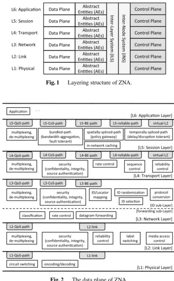
As a result of the consideration above, ZNA adopts the layered model with cross-layer cooperation and ID/Locator split as depicted in Fig. 1. ZNA is composed of six layers.
Each layer is named according to the OSI reference model.
As the figure shows, the data plane and the control plane are separate. The data plane contains the functions for data communication as depicted in Fig. 2 while the control plane contains the functions for network control signaling as de- picted in Fig. 3.Abstract Entities (AEs), Inter-Layer System (ILS),andInter-Node System (INS)are employed for inter- node cross-layer cooperation (see Sect. 5). The session layer (L5) is newly introduced to provide the application layer
Fig. 1 Layering structure of ZNA.
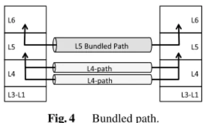
Fig. 2 The data plane of ZNA.
with sophisticated services (see Sect. 3).
In Fig. 2, the shaded rectangles are services provided by a layer to its upper layer while the clear rectangles are functions in each layer. Since ZNA employs ID/Locator split, the network layer is divided into two sub-layers: the ID sub-layerandthe forwarding sub-layer. In the layered model, a service in a layer is realized by some functions in the same layer and some services provided by the lower layer. An example is shown below. The L5-reliable-path service provides the application layer with reliable commu- nication service. In case that the bundled-path in the session layer (see Sect. 3.3) is used, the L5-reliable-path service is realized by the bundled-path function in the session layer and the L4-reliable-path service provided by the transport layer (L4). The L4-reliable-path service is realized by the sequence control function and the reliability control func- tion in the transport layer, and the L3-BE-path (L3 best ef- fort path) service provided by the network layer (L3). The L3-BE-path service is realized by the ID/Locator mapping function and the datagram forwarding function in the net- work layer, and the L2-link service provided by the link layer (L2), and so on.
The rectangles in Fig. 3 are signaling functions in
Fig. 3 The control plane of ZNA.
each layer. To provide the L5-reliable-path service on the bundled-path function, the following signaling functions are used: the L5-reliable-path control signaling, the bundled- path control signaling function, and the reception status feedback function in the session layer; the L4-reliable-path control signaling function and the reception status feedback function in the transport layer; the ID/Locator mapping con- trol signaling function in the link layer and so on.
3. Sophisticated Services Provided by Session Layer
3.1 Roles of Session Layer
The transport layer of the current Internet provides applica- tions with only two kinds of communication services: reli- able byte stream and unreliable datagram. These two ser- vices are too simple to build practical network applications.
To fill the gap between the services provided by the transport layer and the services required by practical applications, ap- plication programs must implement missing functions by themselves. The functions implemented in an application program cannot be shared with other application programs.
There is another approach to fill the gap, in which new func- tions are added in the transport layer to provide the applica- tions with required services. In this approach, applications can utilize the improved transport services. As a result, how- ever, this approach makes implementation of the transport layer very complicated.
ZNA introduces the session layer between the applica- tion layer and the transport layer. The session layer provides the application layer with sophisticated communication ser- vices calledthe L5-pathsby combining the transport layer paths (L4-paths). There are four types of L5-paths:the reg- ular path, the bundled path, the spatially-spliced pathand the temporally-spliced path. By dividing basic communi- cation mechanisms (the transport layer) from sophisticated services (the session layer), a new service can be added by
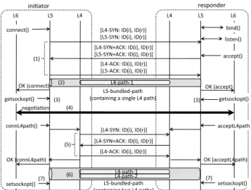
Fig. 4 Bundled path.
modifying the session layer without modifying the transport layer.
3.2 Regular Path
The regular path is a L5-path that is mapped to a single L4- path. It provides the application layer with the same service as the current transport layer provides.
3.3 Bundled Path
The bundled path is a L5-path composed of two or more end-to-end L4-paths as shown in Fig. 4. A L5-path with bandwidth aggregation is realized if two or more L4-paths are used simultaneously. A L5-path with fault tolerance is realized if a single L4-path is used as the primary path and others are reserved as secondary paths. If the primary path becomes unavailable, one of the secondary paths is engaged as the primary path. Thus, the bundled path is a model of multi-path communication.
In the current Internet, SCTP [23] provides the same services as the bundled path provides. The design of SCTP is very complicated because it manipulates simple end-to- end paths and the association composed of several paths in the same layer.
3.4 Spatially-Spliced Path
In the current Internet, most subscribers are connected to the global Internet through a NAT (Network Address Trans- lation) box, which translates private addresses used in the subscriber network into global addresses. Originally, a NAT box was introduced as a means to cope with IPv4 address exhaustion. There are some negative opinions on existence of NAT boxes because it violates the end-to-end principle while there are several advantages on their existence from viewpoint of network operation and management. A NAT box also serves as a firewall or it can apply local policy.
ZNA assumes that middle boxes such as NAT boxes still exist in NwGN from viewpoint of network operation and management. ZNA aims at a network architecture that al- lows existence of middle boxes, not excludes them.
Therefore, ZNA introduces the spatially-spliced path, a model of handling middle boxes, that splices two L4-paths divided spatially as shown in Fig. 5. In Fig. 5, there are two L4-paths divided by the intermediate node calledthe splicer.
The session layer of the splicer splices the two L4-paths to compose the end-to-end L5-path. In the current Internet, if
Fig. 5 Spatially-spliced path.
Fig. 6 Temporally-spliced path.
a NAT box exists on a communication path, a node commu- nicating with another node behind the NAT box regards the NAT box as the correspondent node. In contrast in ZNA, a node can recognize the identifier of the node behind the splicer because ZNA employs an ID/Locator split approach in the network layer.
Upon forwarding a packet in the session layer of a splicer, the splicer can apply its local policy to the packet, e.g., forward the packet, drop the packet, or modify some fields of the session layer header. In addition, the session layer of a splicer can cache the payload of a forwarded packet. Thus, the spatially-spliced path is one of the mech- anisms for in-network cache for ICN.
3.5 Temporally-Spliced Path
In the current Internet, most end nodes are stationary and node mobility is a special case. Based on such an assump- tion, there are a lot of proposals to support node mobility in the Internet. On the other hand, there are research pro- posals that regard mobile nodes as an ordinary case and re- gard stationary nodes as a special case [24]. If node mobil- ity is an ordinary case, a communication mechanism must take communication disruption into account. If communi- cation disruption occurs frequently, communication delay must be larger. Thus, DTN (Delay/Disruption Tolerant Net- work) technologies must be introduced.
Therefore, ZNA introduces the temporally-spliced path, a model of handling communication disruption, that splices several L4-paths not existing at the same time as shown in Fig. 6. At time1 in Fig. 6(a), a L4-path is es- tablished between the leftmost node and the splicer but there is no L4-path between the splicer and the rightmost node. At time2 in Fig. 6(b), the situation is contrary. In the temporally-spliced path, the splicer forwards packets by buffering them.
3.6 Session Layer API
There are several approaches to designing API. One of the approaches is that the API provides application program- mers with high-level functions such as “establish a bundled path for bandwidth aggregation to the specified node.” In this approach, the session layer controlsthe policy, e.g., “un- der what circumstances the bundled path should be used”
and “how many L4-paths should be used.” Another ap- proach is that the API provides application programmers with primitive functions such as “establish a L5-path con- taining a single L4-path,” “add another L4-path to the L5- path,” and “configure the L5-path for bandwidth aggrega- tion.” In this approach, the application layer controls the policywhile the session layer hasthe mechanisms. In the former approach, it is easy for application programmers to use L5-paths but it is almost impossible to control the behav- ior of the session layer. In the latter approach, the features are contrary. ZNA adopts the latter approach because it is desirable that the application can control the behavior of the session layer. As a result, the session layer API in ZNA follows the current socket interface.
In the current Internet, the end point of communication path is calledthe socket. The socket is composed of a port number and an IP address. The IP address specifies (the net- work interface of) the node and the port number specifies the SAP through which the transport layer services are provided to the application layer.
In ZNA, the end point of communication path is also calledthe socket. The socket in ZNA is composed of a port number anda node ID. Since ZNA employs an ID/Locator split approach, a node is specified by its node ID, not its lo- cator. The port number specifies the SAP through which the session layer services are provided to the application layer.
The L4-socket is composed of a port number and a lo- cator. Since ZNA allows coexistence of various network layer (L3) protocols, the format of the locator in the L4- socket depends on the L3 protocol the node uses. The port number of the L4-socket is the same as that of the L5-socket except for the bundled path. In the bundled path, a single L5-socket might be mapped to several L4-sockets.
3.7 Bundled Path Establishment Procedure
Due to space limitation, this paper shows only bundled path establishment procedure in Fig. 7. In the figure, “the ini- tiator” is the node that actively starts path establishment procedure while “the responder” is the node that waits for path establishment request from the initiator. Similar to the TCP connection establishment procedure, the initiator calls socket()andconnect()while the responder calls socket(), bind(), listen(), and accept(). Note thatsocket()calls are omitted in Fig. 7.
In Fig. 7, “ID(i),ID(r)” means that the source node identifier is initiator’s identifier and the destination node identifier is responder’s identifier. When the application
Fig. 7 Bundled path establishment procedure.
in the initiator calls connect(), three messages (L5/L4- SYN, L5/L4-SYN+ACK, and L5/L4-ACK) are exchanged between the session layers in both nodes (Fig. 7(1)). In this procedure, both nodes exchange their locators although Fig. 7 does not show this exchange. As a result, a L5-path containing a single L4-path is established (Fig. 7(2)). Af- ter this, data can be transmitted by send() andrecv().
Next, both nodes obtain the locators of the peer node by getsockopt()(Fig. 7(3)). Next, the applications on both nodes negotiate how many additional L4-paths should be established (Fig. 7(4)). Suppose that the applications de- cide that one more L4-path is necessary. To establish an- other L4-path, the initiator callsconnL4path() while the responder calls acceptL4path(). Then, three messages (L4-SYN, L4-SYN+ACK, and L4-ACK) are exchanged be- tween the transport layers in both nodes (Fig. 7(5)). As a result, the second L4-path is incorporated into the L5-path (Fig. 7(6)). As described in Sect. 3.3, the bundled path has two types: bandwidth aggregation and fault tolerance. The applications in both nodes callsetsockopt()to inform the session layer which type is used (Fig. 7(7)).
3.8 Details and Current Status of the Session Layer See the paper [11] for the details of the session layer API and the communication procedures of the L5-paths. Currently, the session layer has been implemented in the user space of Linux (Ubuntu 10.04), which realizes the bundled path and the spatially-spliced path by using the normal socket API [12]. In addition, the bundled path has been implemented in the kernel space of linux-2.6.38 on top of TCP.
Some performance evaluations about the bundled path implemented in the kernel space are shown be- low. Note that the bundled path establishment pro- cedure in the implementation is slightly different from Fig. 7 because it is implemented on the existing TCP/IP stack, not on the ZNA stack. When the initia- tor establishes a bundled path, it calls the following
system calls: socket(), connect(), getsockopt(), connL4path() and setsockopt(). The establishment time of a bundled path at the initiator is defined as the pe- riod from the time when the initiator callssocket()and the time whensetsockopt()returns. As a result of our mea- surement, the establishment time of a bundled path at the initiator is 2,211µsec+3×RT T, whereRT T is the round trip time between the initiator and the responder.
Next, preliminary results of throughput measurement are shown below. When a bundled path has two L4 connec- tions, the throughput is approximately 1.5 times of that of a single L4 connection. When a bundled path has three L4 connections, the throughput is approximately 1.9 times of that of a single L4 connection. Since the throughput is not so good, it is necessary to improve our bundled path imple- mentation.
4. Mobility and Multi-Homing Support by ID/Locator Split in Network Layer
4.1 Requirements to ID/Locator Split Protocols
We defined the following requirements to the network layer protocol based on ID/Locator split in NwGN: (1) support of network layer (L3) protocol heterogeneity, (2) scalability of ID/Locator mapping system, (3) independence of map- ping information management, and (4) avoidance of loca- tor leakage beyond the administrative boundary. In NwGN, several L3 protocols such as ZNP, IPv4, IPv6, and other pro- tocols will coexist while the current Internet uses only IPv4 and/or IPv6. Therefore, the requirement-(1) must be satis- fied. Nodes that use different L3 protocols must be able to communicate with each other by specifying the identifier of the target node. The requirement-(2) is obvious. A protocol based on ID/Locator split must have an ID/Locator mapping mechanism. To support a huge number of nodes, the map- ping system must be scalable. The requirements-(3) and (4) are related to administration viewpoint. The requirement- (3) means that the mapping information of a node must be managed in the administrative domain to which the node be- longs (the home domain) in terms of authentication of map- ping information when the node is temporally connected to a foreign domain. If the mapping information is managed in administrative domains other than the home domain, it is very difficult to authenticate the mapping information. The requirement-(4) means that the locator information in an ad- ministrative domain must not be registered with the mapping system in other administrative domains. This avoids leakage of the topology information of an administrative domain to the outside.
There are several network layer protocols that supports mobility and multi-homing by ID/Locator split. These pro- tocols can be divided into two approaches. An approach aims at improving the current Internet [25]–[30]. The other approach aims at NwGN [31]–[35]. None of the propos- als described above satisfy the four requirements. ZNP was designed so that it satisfies the requirements.
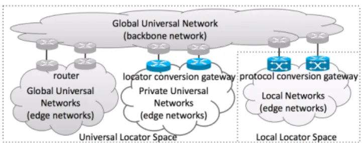
Fig. 8 Assumed network structure of the future Internet.
4.2 Assumed Network Structure
The current Internet is composed of the backbone (i.e., a set of network providers) and a large number of subscriber networks. Some proposals assume that the future Internet has the following structures: there are a lot of domains each of which may use a different locator type, and these do- mains are interconnected and compose a random structure or a multi-level tree structure. However, it is very difficult to manage the network that has such structures. Although there will exist such network structures during atransition period, we assume that thefinalstructure of NwGN converges upon the structure shown in Fig. 8. It is assumed that transition of L3 protocols will be carried out as follows. First, a few network providers start operation of a new L3 protocol in addition to the current L3 protocols. If the new L3 protocol is superior to other L3 protocols from several aspects such as functionality, scalability, and manageability, the number of network providers that adopt the new L3 protocol increases.
As a result, most network providers adopt the new L3 pro- tocol and stop supporting the current L3 protocols. Finally, most subscriber networks also adopt the new L3 protocol and stop using the current L3 protocols. However, a few network providers and subscriber networks might continue to use the current L3 protocols. In Fig. 8, similar to the cur- rent Internet, there is the backbone network composed of several providers and a large number of edge (subscriber) networks. The backbone network uses ZNP and the edge networks may use ZNP or other L3 protocols.
From locator type viewpoint, NwGN is divided into two spaces: the Universal Locator Space (ULoc-Space)in which the locator of ZNP is used andthe Local Locator Space (LLoc-Space)in which legacy L3 protocols such as IPv4/v6 are used. From locator scope viewpoint, the ULoc- Space is further divided into two kinds of networks: the Global Universal Network (GU-Net)in which the scope of the universal locator is the whole future Internet andthe Pri- vate Universal Network (PU-Net)in which the scope of the universal locator is the inside of the network. Some edge networks belong to the GU-Net while some edge networks belong to the PU-Net similar to the current subscriber net- works that connect to the Internet backbone via NAT-like devices. We assume that NAT-like devices still remain in NwGN because there can be administrators who do not want to disclose the network topology to the outside. It is impor-
Fig. 9 ID format.
tant to design an L3 protocol that permits existence of NAT- like devices, not to prohibit existence of them. A network belonging to the LLoc-Space is calledthe L-Net. An L-Net is connected to the GU-Net via the gateways that have pro- tocol conversion function.
4.3 Name and ID
In ZNP,the node nameis a human readable character string and its syntax is the same as that of the FQDN in the current Internet such as node x.keio.jp. The ID is fixed length binary data. The format of the ID is shown in Fig. 9. The ID is composed of three parts: the Registry Identifier, the Organization Identifier, andthe Node Identifier. The Node Identifier is assigned by an organization (e.g., Keio Univ.) to which the node belongs. The Organization Identifier is as- signed by a registry (e.g., JPNIC and APNIC in the current Internet) by which the organization is managed. The Reg- istry Identifier is assigned by an authority such as ICANN in the current Internet.
A node is assigned a locator by the network to which the node is connected. For example, if a node is connected to the ULoc-Space, the node is assigned a universal locator (i.e., a ZNP locator) while if it is connected to the LLoc- Space, it is assigned a local locator such as the IPv4 address.
To support L3 protocol heterogeneity, ZNP introduces the protocol conversion functionon the gateways that connects the ULoc-Space and the LLoc-Space.
4.4 Mapping System Structure
ZNP has two kinds of mapping systems. One isthe Name Mapping System that maps the name to the ID. Another isthe ID Mapping Systemthat maps the ID to the locator.
Thus, ZNP achieves “Internetworking with a Common ID Space.” A node can communicate with another node as long as it knows the ID of the target node even when the target node moves (node mobility), the network to which the target node is connected moves (network mobility), the target node has multiple interfaces (multi-homing), or various L3 pro- tocols coexist (L3 protocol heterogeneity, the requirement- (1)).
The Name Mapping System (NMS) maps the node name to the corresponding ID. The ID Mapping System (IMS) maps the ID of the node to the corresponding loca- tor. The NMS is composed of the Name Mapping Agents (NMAs)and the IMS is composed ofthe ID Mapping Agents (IMAs)as shown in Fig. 10. The NMA and the IMA com- pose tree structures rooted bythe root NMA. Similar to the
Fig. 10 An example of tree structures of the name mapping agents and the ID mapping agents.
current DNS, the hierarchy of the NMS is based on the hier- archical structure of the name. The hierarchy of the IMS is based on the hierarchical structure of the ID shown in Fig. 9.
An NMA holds the locators of the lower level NMAs and an IMA holds the locators of the lower level IMAs. In addi- tion, the NMA of a domain holds the locator of the IMA that manages the same domain.
Figure 10 shows an example of tree structures of the NMS and IMS that manage a domainjpand its two sub- domainsunet.jp andpnet.jp. Suppose that unet.jp uses the GU-Loc (i.e., the global scope ZNP locator) while pnet.jpuses the PU-Loc (i.e., the private scope ZNP loca- tor). Forpnet.jp, there are two kinds of NMAs and IMAs:
the global NMA/IMA and the local NMA/IMA (L-NMA/L- IMA). The global NMA and IMA are located in the GU-Net for the queries sent from the GU-Net. The L-NMA and the L-IMA are located in the PU-Net for the queries sent within the PU-Net. In this example, there are one or more NAT- like gateways at the boundary ofjpandpnet.jpbecause pnet.jpis a PU-Net. The global IMA ofpnet.jpholds the mappings between the IDs of the nodes inpnet.jpand the GU-Loc of the gateway. The L-IMA ofpnet.jpman- ages the mappings between the IDs of the nodes inpnet.jp and their private locators.
As described above, name-to-ID mappings and ID- to-locator mappings are managed in a distributed manner, i.e., each name-to-ID mapping and each ID-to-Locator map- ping are managed by the mapping server of the subdo- main to which the node belongs. Thus, ZNP achieves the scalability of the mapping systems (the requirement-(2)) and independence of mapping information management (the requirement-(3)). In addition, by introducing the L-NMA and the L-IMA, ZNP avoids leakage of private or local loca- tors beyond the administrative boundary (the requirement- (4)).
4.5 Signaling Examples
There are several cases in signaling for locator resolution.
Due to space limitation, this paper introduces one of the sim- plest cases: the requesting node and the target node belong to the GU-Net and they are currently connected to the GU- Net.
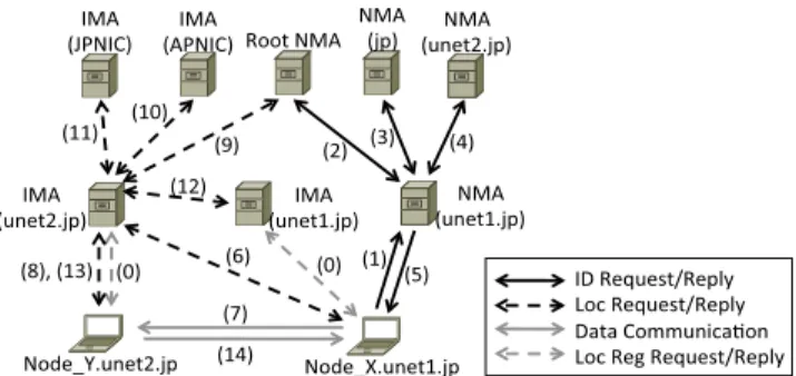
Fig. 11 An example of ID and locator resolution: intra GU-Net.
Suppose that the node Node X.unet1.jp (Node X) wants to communicate with the node Node Y.unet2.jp (Node Y). Both end nodes exist in the GU-Net (i.e., both end nodes use the universal ZNP locator). This procedure is shown in Fig. 11. Before the communication, the end nodes register their own ID-to-Locator mappings with their home domain’s IMA (Fig. 11(0)). Through the procedure shown in Figs. 11(1)–(5), Node X obtains the identifier of Node Y.
Next, Node X obtains the locator of Node Y (Fig. 11(6)) and then Node X sends a packet to Node Y (Fig. 11(7)).
When Node Y returns a reply packet to Node X, the map- ping between the identifier and the locator of Node X is val- idated through the procedure shown in Figs. 11(8)–(13). Fi- nally, Node Y sends a packet to Node X (Fig. 11(14)).
4.6 Details and Current Status of ZNP
See the paper [14] for other signaling examples. The pa- per also designsZ Control Message Protocol (ZCMP)and the neighbor discovery protocol for ZNP called Z Neigh- bor Discovery Protocol (ZNDP). ZCMP manipulates the mapping systems and ZNDP resolves the mapping between the ZNP Locator and link layer address (Locator-to-L2addr mapping). ZNP and ZNDP have been implemented in the linux-2.6.18 kernel space. ZCMP has been implemented in the linux-2.6.18 user space.
Some performance evaluations are shown below. The transmission, reception and forwarding times of a UDP/ZNP packet are 12.65µsec, 5.36µsec, and 7.96µsec, respec- tively, where the total size of the packet is 104 bytes; Eth- ernet header (14 bytes) + ZNP header (72 bytes) + UDP header (8 bytes)+payload (10 bytes). In case of UDP/IPv6 packet, the transmission, reception, and forwarding times are 12.29µsec, 18.91µsec, and 8.81µsec, respectively. The reason why the reception and forwarding times of ZNP are faster than those of IPv6 is that IPv6 has some functions, e.g., multicast handling, that the current implementation of ZNP does not have.
The ID resolving time (Tid) is represented as Tid = (Tproc+RT T)×(n+1), whereTproc is the query process- ing time of the NMA or the IMA, RT T is the round trip time, and nis the number of hierarchy levels of the node name. The locator resolving time (Tloc) is represented as Tloc=(Tproc+RT T)×(n+2). If the requesting node has the
cache,Tid=Tloc=0. As a result of our measurement,Tproc
is approximately 38.65µsec.Tproc is negligible in compari- son withRT T, which is usually in msec order.
5. Adaptation to Dynamically Changing Network Con- ditions by Inter-Node Cross-Layer Cooperation
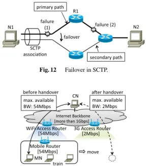
5.1 Effectiveness of Inter-Node Cross-Layer Cooperation The following two examples show effectiveness of inter- node cross-layer cooperation. The first example shows co- operation between the L2 of a router and the L4 of an end node. In Fig. 12, two nodes N1 and N2 are communicating with each other through an SCTP association. An SCTP as- sociation can have multiple paths, one of which is used as the primary path and others are reserved as secondary paths.
When the primary path fails, one of the secondary paths is engaged as the primary. This procedure is called failover.
In the example, the SCTP association has two paths and the upper path is used as the primary. Suppose that link failure- (1) occurs. SCTP in the end node N1 can detect this fail- ure through cooperation between the L2 and the L4 in N1.
Then, N1 can start the failover procedure. Suppose that link failure-(2) occurs. Both end nodes, however, cannot detect this link failure through intra-node cross-layer cooperation.
If the L4 in N1 and L2/L3 in R1 cooperate, the L4 in N1 can detect link failure-(2) immediately and start the failover procedure.
The second example shows cooperation between the L2 and the L3 of a mobile router (MR) in a mobile net- work and the L4 of a mobile node in the mobile network.
In Fig. 13, a mobile network is connected to the global In- ternet through a WiFi link. A mobile node (MN) in the mo- bile network is communicating with a correspondent node (CN) in the global Internet. The mobile network is going to
Fig. 12 Failover in SCTP.
Fig. 13 Bandwidth change due to mobile network handover.
handover from a WiFi access router to a 3G access router.
As a result, the bandwidth of the wireless link is reduced from 54 Mbps to 2 Mbps. Without an inter-node cross-layer cooperation mechanism, the MN cannot detect bandwidth reduction due to handover and keeps the transmission rate (the congestion window size in case of TCP) after handover.
This causes heavy congestion at the MR. If the L4 in the MN and L2/L3 in the MR cooperate, the L4 in the MN can detect that a handover to a lower access point is about to occur and adjust the congestion window size so that congestion at the MR is avoided.
5.2 Requirements to Cross-Layer Cooperation Mecha- nisms
In the two examples described in Sect. 5.1, control informa- tion is transferred from a layer in a node to a layer in an- other node and the two layers are not the same layer. In the two examples, control information is exchanged between the L4 in an end node and the L3 or the L2 in a router.
There are several protocols in the L4, the L3, and the L2, and there are a lot of device types in the L2. To enable such interactions, control information must be transformed from protocol- or device-specific information to protocol- or device-independent information. In addition to information abstraction, each layer must define primitives as a clearly- defined API, which makes inter-node cross-layer coopera- tion easier. In the second example in Sect. 5.1, the two nodes that exchange control information are basically connected to the same subnet while in the first example, the two nodes that exchange control information might be located a lot of hops away. Therefore, an inter-node cross-layer cooperation mechanism must be available in a wide area network.
As a result of the discussion above, we defined the fol- lowing five requirements to inter-node cross-layer coopera- tion architectures: (1) cooperation between a layer in a node and a layer (not necessary the same layer) in another node, (2) abstraction of control information, (3) definition of prim- itives in each layer, (4) availability in wide area networks, and (5) implementation. The fifth requirement means that an inter-node cross-layer cooperation architecture can be im- plemented in real systems.
A lot of cross-layer cooperation architectures have been proposed [36]–[45]. Some of them focus on mobility in wireless communication environment while some of them focus on multimedia communication. Most cross-layer co- operation architectures in the literature consider cooperation of layers withina node (intra-node). In addition to intra- node cross-layer cooperation, inter-node cross-layer cooper- ation should be employed to efficiently adapt to the dynam- ically changing network conditions. None of the proposals described above satisfy the five requirements. CLINEX was designed so that it satisfy the requirement.
5.3 CLINEX Architecture
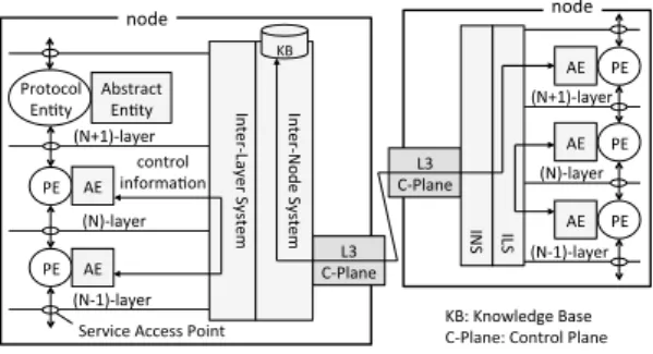
Figure 14 shows the CLINEX architecture. The OSI ref-
Fig. 14 CLINEX architecture.
erence model defines the Protocol Entity (PE) which pro- cesses a protocol in a layer. For example, in the L3 in the current Internet, there is IP-PE. PEs in adjacent layers ex- change data through a SAP (Service Access Point).
CLINEX employsthe Abstract Entity (AE),the Inter- Layer System (ILS), andthe Inter-Node System (INS)in each node. An AE is attached to each PE. The ILS vertically pen- etrates all layers like a skewer. An AE abstracts protocol- specific control information to protocol-independent control information (the requirement-(2)). Abstracted control infor- mation is exchanged between layers that might not be ad- jacent through the ILS. The INS exchanges abstracted con- trol information between nodes (the requirement-(1)). The L3 control plane is responsible for abstracted control infor- mation exchange between nodes in wide area networks (the requirement-(4)). In addition,the KB (Knowledge Base)is installed in representative nodes of administrative areas such as the areas of OSPF (Open Shortest Path First), one of the standard intra-AS routing protocols. The KB is a database that stores information of the network such as the topology of the coverage area and available bandwidth of each link in the coverage area.
5.4 Message and Service Types
CLINEX defines four classes of messages: the Request (req), the Confirm (conf), the Indication (ind), andthe Re- sponse (res). The Request is used when an AE in a layer (e.g, the L3) requests some action of an AE in the target layer (e.g., the L2). The Confirm is the reply to the Request.
The Indication notifies the requesting AE in a layer (e.g., the L3) of occurrence of an asynchronous event in the target AE in another layer (e.g., the L2). The Response is the reply to the Indication.
CLINEX defines three service types as shown in Fig. 15. In the Information service, a requesting AE in a layer (e.g., the L3) sends the Request to the target AE in another layer (e.g., the L2). The target AE replies with the Confirm to the requesting AE. In the Event Service, a re- questing AE in a layer registers a request with the target AE in another layer through the Request. The target AE replies with the Confirm as an acknowledgment of the Re- quest. When the requested event occurs in the target AE, it notifies the requesting AE of the event through the Indi-
Fig. 15 CLINEX interaction model.
Table 1 L2 primitives in CLINEX.
type primitive function
IS L2-IfList query of i/f list in L2 IS L2-IfStat query of i/f status in L2 IS L2-PoAList query of PoA list IS L2-LinkStat query of link status
ES L2-IfListChanged notification that i/f list changed ES L2-IfStatChanged notification that i/f status changed ES L2-PoAListChanged notification that PoA list changed ES L2-LinkStatChanged notification that link status changed CS L2-LinkConnect command to connect to specified PoA CS L2-LinkDisconnect command to disconnect from a PoA
cation. The requesting AE would reply with the Response to the target AE. In the Command Service, the requesting AE in a layer sends the Request to the target AE to execute some action. The target AE replies with the Confirm as an acknowledgment of the Request.
5.5 L2 and L3 Primitives
To satisfy the requirement-(3) (definition of primitives), CLINEX defines primitives in the L2 and the L3 as the first step of its design.
5.5.1 L2 Primitives
It can be assumed that indispensable control information in the L2 is regarding physical interfaces and L2 links. There- fore, it would be sufficient to provide an AE in other layers with the following information: what kinds of physical in- terfaces are installed; what the status of an interface is; what node is connected through an interface via a wired link; what node could be connected through an interface via a wireless link; and what the status of the L2 link is. Thus, CLINEX defines the ten L2 primitives as shown in Table 1. There are four Information Service (IS) primitives, four Event Service (ES) primitives, and two Command Service (CS) primitives.
5.5.2 L3 Primitives
It can be assumed that indispensable control information in the L3 is regarding interfaces visible in the L3 and paths be- tween a pair of nodes. Therefore, it would be sufficient to provide an AE in other layers with the following informa- tion: what kinds of interfaces are visible in the L3; what the
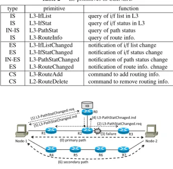
Table 2 L3 primitives in CLINEX.
type primitive function
IS L3-IfList query of i/f list in L3 IS L3-IfStat query of i/f status in L3 IN-IS L3-PathStat query of path status
IS L3-RouteInfo query of route info.
ES L3-IfListChanged notification of i/f list change ES L3-IfStatChanged notification of i/f status change IN-ES L3-PathStatChanged notification of path status change
ES L3-RouteChanged notification of route info. chnage CS L3-RouteAdd command to add routing info.
CS L2-RouteDelete command to remove routing info.
Fig. 16 Example of L3-PathStatChanged processing.
status of an interface is; what the status of a path to another node is; and what the status of the routing information is.
Thus, CLINEX defines the ten L3 primitives as shown in Table 2. There are four Information Service (IS) primi- tives, four Event Service (ES) primitives, and two Command Service (CS) primitives.IN-ISmeans inter-node IS andIN- ESmeans inter-node ES.
5.6 L3-PathStatChanged Processing
Due to space limitation, this paper shows an example of the CLINEX procedures. Figure 16 shows the CLINEX proce- dure in the SCTP failover procedure shown in Fig. 12. Note that the Confirm messages (e.g., L3-PathStatChanged.conf) as the acknowledgement of the Request messages (e.g., L3-PathStatChanged.req) are omitted in the figure. First, Node-1 and Node-2 start SCTP communication via the primary path (Fig. 16(0)). Suppose that SCTP (L4) in Node-1 wants to know status change on the primary path.
SCTP in Node-1 sends the L3-PathStatChanged.req mes- sage containing the information about both end nodes to KB node (Fig. 16(1)). Since the KB node knows that R1, R2, and R3 are on the primary path, it sends the L3- PathStatChanged.req message to those nodes (Fig. 16(2)).
Note that a single L3-PathStatChanged.req message is sent by the KB node. The message is copied in R2 and for- warded to R1 and R3. In R1, R2, and R3, upon re- ceiving the L3-PathStatChanged.req message, the L3 sends the L2-LinkStatChanged.req message to the L2 to detect link failure. Suppose that link failure occurs on the link between R2 and R3 (Fig. 16(3)). The L2 of R2 detects this link failure and it sends the L2-LinkStatChanged.ind message to the L3 of R2. Upon receiving the message, since the L3 knows that the status of the path specified by the L3-PathStatChanged.req changed, it sends the L3-
PathStatChanged.ind message to the KB node (Fig. 16(4)).
Upon receiving the L3-PathStatChanged.ind message, the KB node forwards it to Node-1 (Fig. 16(5)). As a result, Node-1 performs failover to the secondary path (Fig. 16(6)).
5.7 Details and Current Status of CLINEX
See the paper [15] for the detailed procedure of CLINEX.
The main part of CLINEX has been implemented in the ker- nel space and the user space of Ubuntu 12.04.1 LTS (linux- 3.2.0). The ILS is implemented in the kernel space and the INS is implemented in the user space. Some AEs are imple- mented in both the kernel space and the user space.
One of performance evaluations is shown below. Sup- pose that an application process on a node wants to know occurrence of congestion on its communication path and a router on the communication path detects congestion. On the router, an L3-AE in the kernel space detects conges- tion and it notifies an L3-AE in the user space of the event (38µsec). The L3-AE in the user space generates an L3- PathStatChanged.ind message (16µsec) and sends the mes- sage to the ILS in the kernel space (7µsec). The ILS judges that the message is an inter-node message (5µsec) and it sends the message to the INS in the user space (45µsec).
The INS in the user space sends the message to the node (23µsec + delay from the router to the node). On the node, the INS in the user space receives the message and knows that the message is an L3-PathStatChanged.ind mes- sage (25µsec) and sends it to the ILS in the kernel space (9µsec). The ILS in the kernel space judges that this mes- sage should be sent to L6 (the application layer)-AE (7µsec) and sends the message to the L6-AE in the user space (25µsec). The L6-AE receives the message (21µsec) and notifies the application process that congestion occurred on the router (54µsec). Thus, it takes 275+delayµsec from the time when the L3-AE in the router detects congestion to the time when the application process receives the noti- fication, wheredelayis the communication delay from the router to the node.
6. Conclusion
This paper introduced a new network architecture called ZNA for New Generation Network. First, this paper dis- cussed the layered model, cross-layer cooperation, informa- tion centric networking, and ID/Locator split. As a result, ZNA adopts a six-layer model with inter-node cross-layer cooperation and ID/Locator split. Among the features of ZNA, this paper introduced three of them: (1) sophisticated services in the session layer, (2) support of mobility, multi- homing, and heterogeneity of network layer protocols, and (3) inter-node cross-layer cooperation.
As the sophisticated services, ZNA defined three kinds of communication paths in the session layer: the bundled- path, the spatially-spliced-path, and the temporally-spliced path. The session layer API was defined and an example of a bundled path establishment procedure was shown. As the
network layer protocol for NwGN, four requirements were defined. ZNP was designed so that the four requirements were satisfied. ZNP adopted ID/Locator split approach to support mobility, multi-homing, and heterogeneity of net- work layer protocols. The mapping systems of ZNP were also introduced and an example of ID and locator resolu- tion was shown. As the cross-layer cooperation for NwGN, five requirements were defined. CLINEX was designed so that the five requirements were satisfied. CLINEX realizes exchange of control information between layers not only in the same node but also in different nodes to adapt to the dynamically changing network conditions. An example of CLINEX signaling was shown, in which the L4 in an end node cooperates with the L2 and L3 on a router so that the L4 in the end node can detect L2 failure in the router.
Currently, some parts of ZNA have been implemented.
We are revising the design and the protocols of ZNA re- flecting the findings through the implementation. There are protocols and functions that have not yet been implemented.
We continue improvement and implementation of ZNA. We would like to build a test network based on ZNA using a network virtualization technique in the near future.
References
[1] D. Clark, K. Sollins, J. Wroclawski, D. Katabi, J. Kulik, X. Yang, M. Handley, and N. Chiappa, “Final Technical Report, New Arch:
Future Generation Internet Architecture,” tech. rep., MIT Computer Science & Artificial Intelligence Lab., USC Information Science In- stitute, and University College London, 2003.
[2] H. Zhang, D.A. Maltz, and E.W. Knightly, “Collaborative Research:
ITR/ANIR: 100 Mb/sec For 100 Million Households,” tech. rep., AT&T, University California Berkeley, Carnegie Mellon University, Fraser Research, Internet2, Pittsburgh Supercomputer Center, Rice University, and Stanford University, March 2003.
[3] “FIND (Future Internet Design) Home Page.” http://www.nets- find.net/
[4] “FIA (Future Internet Architecture) Home Page.” http://www.nets- fia.net/
[5] “GENI (Global Environment for Network Innovations) Home Page.”
http://www.geni.net/
[6] “FP7 (Seventh Framework Programme), ICT (Information and Communication Technologies) Home Page.” http://cordis.europa.eu/ fp7/ict/
[7] “Trilogy Project Home Page.” http://inl.info.ucl.ac.be/projects/ trilogy
[8] “4WARD Project Home Page.” http://www.4ward-project.eu/ [9] “AKARI Project Home Page.” http://akari-project.nict.go.jp/ [10] F. Teraoka, “Redesigning layered network architecture for new gen-
eration networks,” Proc. 2nd IEEE Workshop on the Network of the Future, pp.1–6, Dec. 2009.
[11] F. Teraoka, S. Kanemaru, and K. Yonemura, “ZNA: A network ar- chitecture for new generation network — Focusing on the session layer,” Proc. 3rd International Conference on Ubiquitous and Future Networks (ICUFN 2011), pp.309–414, June 2011.
[12] M. Ide, K. Kaneko, and F. Teraoka, “Validation of session layer pro- tocols and API in ZNA,” Proc. Asian Internet Engineering Confer- ence 2012 (AINTEC’12), pp.77–84, Nov. 2012.
[13] S. Kanemaru and F. Teraoka, “ZNP: A network layer protocol based on ID/locator split considering practical operation,” Proc. IEEE In- ternational Conference on Communications 2011 (ICC2011), pp.1–
6, June 2011.
[14] S. Kanemaru, K. Yonemura, and F. Teraoka, “ZNP: A new gen-
eration network layer protocol based on ID/locator split consider- ing practical operation,” IEICE Trans. Commun., vol.E96-B, no.3, pp.764–777, March 2013.
[15] K. Yonemura, K. Kaneko, and F. Teraoka, “CLINEX: An inter-node cross-layer cooperation architecture to adapt to dynamically chang- ing network situation,” Proc. 2013 IEEE 37th Annual Computer Software and Applications Conference (COMPSAC 2013), pp.33–
42, July 2013.
[16] ISO, “Information technology — Open Systems Interconnection — Basic Reference Model: The Basic Model,” Nov. 1994. ISO/IEC 7498-1.
[17] R. Braden, T. Faber, and M. Handley, “From protocol stack to pro- tocol heap — Role based architecture,” ACM SIGCOMM Computer Communications Review, vol.33, no.1, pp.17–22, Jan. 2003.
[18] R. Dutta, G.N. Rouskas, I. Baldine, A. Bragg, and D. Stevenson,
“The SILO architecture for services integration, control, and op- timization for the future Internet,” Proc. IEEE International Con- ference on Communications 2007 (ICC 2007), pp.1899–1904, June 2007.
[19] T. Koponen, M. Chawla, B.G. Chun, A. Ermolinskiy, K.H. Kim, and S. Shenker, “A data-oriented (and beyond) network architecture,”
Proc. SIGCOMM’07, pp.181–192, Aug. 2007.
[20] V. Jacobson, D.K. Smetters, J.D. Thornton, M.F. Plass, M.H.
Briggs, and R.L. Braynard, “Networking named content,” Proc.
CoNEXT’09, pp.1–12, Dec. 2009.
[21] “PSIRP: Publish-Subscribe Internet Routing Paradigm.” http://www.
psirp.org/home.html
[22] F. Teraoka, K. Gogo, K. Mitsuya, R. Shibui, and K. Minani, “Unified Layer-2 (L2) abstractions for Layer-3 (L3)-driven fast handover,”
RFC 5184, May 2008.
[23] R. Stewart, “Stream control transmission protocol,” RFC 4960, Sept.
2007.
[24] “MobilityFirst Project Home Page.” http://mobilityfirst.winlab.
rutgers.edu
[25] C. Vogt, “Six/One Router: A scalable and backwards compatible solution for provider-independent addressing,” Proc. MobiArch ’08, pp.13–18, Aug. 2008.
[26] D. Farinacci, V. Fuller, D. Meyer, and D. Lewis, “The locator/ID separation protocol (LISP),” RFC 6830, Jan. 2013.
[27] M. Ishiyama, M. Kunishi, K. Uehara, H. Esaki, and F. Teraoka,
“LINA: A new approach to mobility support in wide area net- works,” IEICE Trans. Commun., vol.E84-B, no.8, pp.2076–2086, Aug. 2001.
[28] R. Atkinson, S. Bhatti, and S. Hiles, “ILNP: Mobility, multi-homing, localised addressing and security through naming,” Telecommunica- tion Systems, vol.42, no.3-4, pp.273–291, Dec. 2009.
[29] P. Nikander, A. Gurtov, and T.R. Henderson, “The host identity pro- tocol (HIP): Connectivity, mobility, multi-homing, security, and pri- vacy over IPv4 and IPv6 networks,” IEEE Commun. Surveys and Tutorials, vol.12, no.2, pp.186–204, April 2010.
[30] R. Inayat, R. Aibara, K. Nishimura, T. Fujita, and K. Maeda, “An end-to-end network architecture for supporting mobility in wide area wireless networks,” IEICE Trans. Commun., vol.E87-B, no.6, pp.1584–1593, June 2004.
[31] B. Ahlgren, J. Arkko, L. Eggert, and J. Rajahalme, “A node identity internetworking architecture,” Proc. INFOCOM 2006, pp.1–6, April 2006.
[32] S. Sch¨utz, H. Abrahamsson, B. Ahlgren, and M. Brunner, “Design and implementation of the node identity internetworking architec- ture,” Computer Networks: The International Journal of Computer and Telecommunications Networking, vol.54, no.7, pp.1142–1154, May 2010.
[33] V.P. Kafle and M. Inoue, “HIMALIS: Heterogeneity inclusion and mobility adaptation through locator ID separation in new genera- tion network,” IEICE Trans. Commun., vol.E93-B, no.3, pp.478–
489, March 2010.
[34] A. Feldmann, L. Cittadini, W. M¨uhlbauser, R. Bush, and
O. Maennel, “HAIR: Hierarchical architecture for Internet routing,”
Proc. 2009 Workshop on Rearchitecting the Internet, pp.43–48, Dec.
2009.
[35] J. Pan, S. Paul, R. Jain, and M. Bowman, “MILSA: A mobility and multihoming supporting identifier locator split architecture for nam- ing in the next generation Internet,” Proc. IEEE GLOBECOM 2008, pp.1–6, Dec. 2008.
[36] Q. Wang and M.A. Abu-Rgheff, “Cross-layer signalling for next- generation wireless systems,” Proc. IEEE Wireless Communications and Networking 2003 (WCNC 2003), pp.1084–1089, March 2003.
[37] M. Conti, G. Maselli, G. Turi, and S. Giordano, “Cross-layering in mobile ad hoc network design,” Comput., vol.37, no.2, pp.48–51, Feb. 2004.
[38] E. Borgia, M. Conti, and F. Delmastro, “Mobileman: Design, inte- gration, and experimentation of cross-layer mobile multihop ad hoc networks,” IEEE Commun. Mag., vol.44, no.7, pp.80–85, July 2006.
[39] R. Winter, J.H. Schiller, N. Nikaein, and C. Bonnet, “CrossTalk:
Cross-layer decision support based on global knowledge,” IEEE Commun. Mag., vol.44, no.1, pp.93–99, Jan. 2006.
[40] V.T. Raisinghani and S. Iyer, “Architecting protocol stack optimiza- tions on mobile devices,” Proc. First International Conference on Communication System Software and Middleware 2006 (Comsware 2006), pp.1–10, 2006.
[41] K.M.E. Defrawy, M.S.E. Zarki, and M.M. Khairy, “Proposal for a cross-layer coordination framework for next generation wireless sys- tems,” Proc. 2006 International Conference on Wireless Communi- cations and Mobile Computing (IWCMC ’06), pp.141–146, 2006.
[42] IEEE, IEEE Standard for Local and metropolitan area networks — Part21: Media Independent Handover Services, Jan. 2009. IEEE Std 802.21-2008.
[43] Z. Chang and G. Gaydadjiev, “A hybrid cross layer architecture for wireless protocol stacks,” Proc. Wireless Communications and Mo- bile Computing Conference 2008 (IWCMC ’08), pp.279–285, Aug.
2008.
[44] X. Ren and J. Zhang, “A novel cross-layer architecture for wireless protocol stacks,” Proc. 2010 International Conference on Multime- dia Technology (ICMT 2010), pp.1–6, Oct. 2010.
[45] T. Taleb, K. Kashibuchi, A. Leonardi, S. Palazzo, K. Hashimoto, N. Kato, and Y. Nemoto, “A cross-layer approach for an efficient delivery of TCP/RTP-based multimedia applications in heteroge- neous wireless networks,” IEEE Trans. Veh. Technol., vol.57, no.6, pp.3801–3814, Nov. 2008.
Fumio Teraoka is a professor of Faculty of Science and Technology, Keio University. He received a master degree in electrical engineer- ing and a Ph.D. in computer science from Keio University in 1984 and 1993, respectively. He joined Canon Inc. in 1984 and then moved to Sony Computer Science Labs., Inc. (Sony CSL) in 1988. Since April 2001, he is a professor of Faculty of Science and Technology, Keio Uni- versity. He received the Takahashi Award of JSSST (Japan Society for Software Science and Technology) and the Motooka Award in 1991 and 1993, respectively. He also received the Best Paper Award in 2000 from IPSJ (Information Pro- cessing Society Japan). His research interest covers computer network, operating system, and distributed system. He contributed to the activity of the Mobile working group of IETF by developing Virtual IP (VIP). He was a board member of the WIDE Project from 1991 to 2010. He was a board member of IPSJ from 2000 to 2002. He was a board member of JSSST from 2005 to 2009. He is a member of ACM, IEEE, JSSST, IPSJ, and IEICE.
Sho Kanemaru received a master degree in School of Science for Open and Environmental Systems, Graduate School of Science and Tech- nology, Keio University, Japan in 2012. He is interested in new generation network technolo- gies, especially, ID/Locator split approach and implementation of the protocols in Linux ker- nel space. Currently, he works at NTT Network Service Systems Laboratories.
Kazuma Yonemura received a master de- gree in School of Science for Open and En- vironmental Systems, Graduate School of Sci- ence and Technology, Keio University, Japan in 2013. He is interested in new generation net- work technologies, especially, ID/locator split approach and cross-layer cooperation. Cur- rently, he works at DWANGO Co., Ltd.
Motoki Ide received a master degree in School of Science for Open and Environmen- tal Systems, Graduate School of Science and Technology, Keio University, Japan in 2014. He is interested in new generation network tech- nologies, especially, sophisticated communica- tion services in the session layer. Currently, he works at Nomura Research Institute.
Shinji Kawaguchi is a master course stu- dent in School of Science for Open and Envi- ronmental Systems, Graduate School of Science and Technology, Keio University, Japan. He is interested in cross-layer cooperation technolo- gies.
Kunitake Kaneko is an assistant professor of Faculty of Science and Technology at Keio University. He received his M.S. from Graduate School of Engineering, the University of Tokyo, and his Ph.D. from the Graduate School of In- formation Science and Technology. In 2006, he joined Research Institute for Digital Media and Content (DMC) at Keio University. His research interest is in new generation network architec- ture from network applications’ perspective. He is a member of IEEE, SMPTE, IPSJ, and IEICE.