EtherNet/IPは、ネットワーク・プロトコル・ファミリのメンバーであり、 上位層に Common Industrial Protocol(CIP)を実装しています。EtherNet/IPとは、IEEE
802.3で定義される標準イーサネット上にCIPを実装する場合、 そのCIPに与えら
れる名前です。CIPを利用するその他の産業用プロトコルには、DeviceNet™、
ControlNet™、CompoNet™などがあります。図1には、CIPベースの4つのプロ
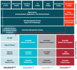
トコルと、それらが共有するプロトコル層との関係を示します。これらのプロトコル 層には、接続管理、データ管理サービス、オブジェクト・ライブラリ、いくつかのユー スケース・プロファイルなどが含まれています。
EtherNet/IP
テクノロジー リアルタイム・ネットワーク環境を作り出すCIPは、メディアに依存しない、接続ベー スのオブジェクト指向プロトコルであり、制御、安全性、同期、動作、構成、情報 といったファクトリー・オートメーション向けの通信サービスを完備しています。世界 の何百ものベンダーによってサポートされているCIPは、広範囲にわたるデバイス の相互運用性に役立っています。 概要 EtherNet/IP™(EtherNet/Industrial Protocol)は、過去30年間にわたってITネッ トワーク業 界 の 中 心を担ってきたIEEE 802.3イーサネット規格に基づく、 産業用 オートメーション・ネットワーク・プロトコル です。イーサネットは、さまざまなビジネス・ アプリケーションにおいて圧倒的な成功を 収めていますが、 標準イーサネットが決定 性プロトコルではないことから、プロセス 制御やモーター制御などのアプリケーショ ンに必要なリアルタイムの動作が保証でき ないため、 産業用アプリケーション向けに 変更を加える必要があります。 EtherNet/IPは、IEEE 802.3およびTCP/ IPプロトコル・スイートに完全に対応して いるため、 その主要ターゲットである産業 用リアルタイム・アプリケーションだけでな く、 企業サーバともシームレスに通信でき ます。工場の現場と企業をつなぐコミュニ ケ ー シ ョン の 架 け 橋 を 作 る こ と で、 EtherNet/IPは、 製造スケジュールのより 効率的な管理、在庫コストの最小化、その 他のビジネス向け機能の最適化などを実現 します。 2001年の登場以来、EtherNet/IPは、“The EtherNet/IP Specification”の発行や適合 性試験の調整といった役割も担う、Open DeviceNet Vendor Association, Inc. (ODVA)によって管理されています。TI
の
Sitara
™
プロセッサ上の
EtherNet/IP
™
Vineet Roy, ソフトウェア・システム・エンジニア テキサス・インスツルメンツホ ワ イ ト ペ ー パ ー
図 1:DeviceNet、CompoNet、および ControlNet は、Ether Net/IP と同じCIP アプリケーション層を共有
EtherNet/IP is a member of a family of network protocols that implements the Common Industrial Protocol (CIP) at its upper layers. EtherNet/IP is the name given to CIP when it is implemented over standard Ethernet as defined by IEEE 802.3. Other industrial protocols that utilize CIP include DeviceNet™, ControlNet™ and CompoNet™. Figure 1 shows the relationship between the four CIP-based protocols and the protocol layers they share, which include connection management, data management services, an object library and a number of use-case profiles.
EtherNet/IP technology
The CIP that creates a real-time networking environment is a media-independent, connection-based, object-oriented protocol that provides a complete set of communication services for factory automation, including control, safety, synchronization, motion, configuration and information. CIP is supported by hundreds of vendors globally, which provides widespread interoperability of devices.
Overview
EtherNet/IP™ (EtherNet/Industrial Proto-col) is an industrial automation network-ing protocol based on the IEEE 802.3 Eth-ernet standard that has dominated the world of IT networking for the past three decades. Despite Ethernet’s unparalleled success in a wide range of business plications, modifications for industrial ap-plications are necessary because standard Ethernet is not a deterministic protocol and therefore cannot guarantee the real-time operation required by applications such as process control and motor control.
Since it is fully compatible with IEEE 802.3 and the TCP/IP protocol suite, Eth-erNet/IP can communicate seamlessly with enterprise servers as well as its pri-mary targets – real-time industrial ap-plications. By creating a communications bridge between the factory floor and the enterprise, EtherNet/IP makes it possible to manage production schedules more ef-ficiently, minimize inventory costs and op-timize other business oriented functions. Introduced in 2001, EtherNet/IP is man-aged by the Open DeviceNet Vendor Associa-tion, Inc. (ODVA), which also has responsibility for publishing The EtherNet/IP Specifica-tion and coordinating conformance testing.
EtherNet/IP
™
on
TI’s Sitara
™
processors
Vineet Roy, Software Systems Engineer Texas Instruments
W H I T E P A P E R
Figure 1: DeviceNet, CompoNet & ControlNet share the same CIP application layer with EtherNet/IP. CIP Motion™ Profiles Motor Control Profiles Transducer Profiles I/O Profiles DeviceNet Network and Transport
ControlNet Network and Transport
ControlNet CTDMA ControlNet Physical Layer CAN CDMA/NBA DeviceNet Physical Layer CompoNet
Network and Transport
CompoNet Time Slot
CompoNet Physical Layer
TCP/UDP
EtherNet/IP™ CompoNet™ ControlNet™ DeviceNet™
Internet Protocol
Ethernet CSMA/CD
Ethernet Physical Layer
Common Industrial Protocol (CIP)
Network Applications of CIP
Object Library
(Communications, Applications, Time Synchronization) Other Profiles Semiconductor Profiles CIP Safety™ Profiles Safety Object Library Safety Services and Messages Data Management Services
Explicit and I/O Messages
Connection Management, Routing
Originator Services for Modbus Device Integration
®
EtherNet/IP™ on TI’s Sitara™ processors February 2015 CIPは、その厳密な適合プログラムによって、製造企業全体にわたって統一された通信アーキテ クチャを提供します。CIPの利点としては、主に次のようなものが挙げられます。 I/O制御、デバイス構成、データ収集などの一貫性のある統合 複数ネットワーク間でのシームレスな情報フロー 複雑なブリッジやプロキシを必要としない低コストの多層ネットワークの実装 システムの設計、導入、コミッショニングへの投資が最小限 手頃な価格と低い統合コストで、最適な製品を自由に組み合わせて選択可能 図2には、マルチプロトコル環境を実現するために、EtherNet/IPが、 標準IEEE 802.3および
TCP/IPプロトコル・スイート上でCIPを利用するメリットについて示します。EtherNet/IPは標準イー
サネットやTCP/IPのテクノロジーを利用しているため、他のアプリケーションやプロトコルとの互 換性、共存性が保証されています。EtherNet/IPは、統合と相互運用性を優先して設計されており、 選択できる実装方法は1つだけではありません。 アプリケーションのソフトウェア・プログラミングを単純化するため、CIPにはオブジェクト・モデ ルが採用されています。このモデルでは、共通のインターフェイスや動作を定義するアプリケーショ ン・オブジェクトとデバイス・プロファイルのセットを、CIPアプリケーション層で定義します。CIP 通信サービスによって、異なるCIPネットワーク上にあるデバイス間でのエンド・ツー・エンド通 信も可能になります。EtherNet/IPでは、デバイス間のマルチベンダー相互運用性を実現するた めに、CIP通信サービスをイーサネットとTCP/IPに対応付けています。 次ページの図3には、CIPアプリケーション層内部の各デバイスが、オブジェクト・モデルを使っ てどのように表されるかを示します。機能的な観点から見ると、3つのクラスのオブジェクトが含 まれています。これらすべてが必須のオブジェクトというわけではありません。 オブジェクト指向の プログラミング・モデル 図 2:CIP はイーサネットやインターネット・プロトコルに完全対応することでマルチプロトコル・サポートを実現
EtherNet/IP™ on TI’s Sitara™ processors February 2015
Because of its rigorous conformance programs, CIP offers a unified communication architecture across the manufacturing enterprise. Its most commonly cited benefits are:
• Coherent integration of I/O control, device configuration and data collection • Seamless information flow across multiple networks
• Implementation of multi-layer networks without the cost and complexity of bridges and proxies • Minimized investment in system engineering, installation and commissioning
• Freedom to choose best-of-breed products at competitive prices and low integration cost
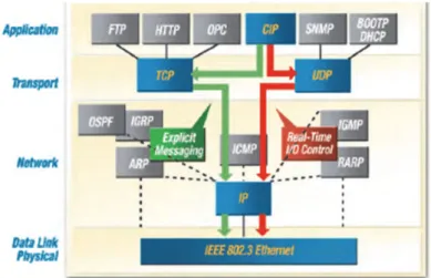
Figure 2 illustrates the value of EtherNet/IP utilizing CIP over standard IEEE 802.3 and the TCP/IP protocol suite to enable a multi-protocol environment. Because EtherNet/IP uses standard Ethernet and TCP/IP technologies, compatibility and coexistence with other applications and protocols is assured. Integration and interoperability are high priorities for EtherNet/IP, which means that more than one path can be taken to implementation.
To simplify the software programming of an application, CIP has adopted an object model in which the CIP application layer defines a set of application objects and device profiles that define common interfaces and behaviors. CIP communication services also enable end-to-end communication between devices on the dif-ferent CIP networks. To enable multi-vendor interoperability between devices, EtherNet/IP maps CIP commu-nication services to Ethernet and TCP/IP.
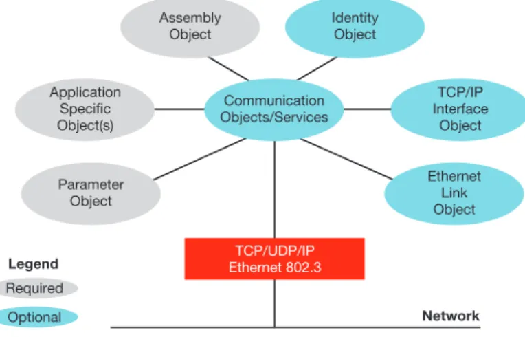
Figure 3 on the following page shows how devices are represented using an object model within the CIP application layer. From a functional perspective, three classes of objects are included. Not all of them are required.
Figure 2: Multi-protocol support is possible because CIP is fully compatible with Ethernet and Internet protocols. EtherNet/IP Technology The CIP that creates a real‐time networking environment is a media independent, connection‐based, object‐oriented protocol that provides a complete set of communication services for factory automation, including control, safety, synchronization, motion, configuration and information. CIP is supported by hundreds of vendors globally, which provides widespread interoperability of devices. Because of its rigorous conformance programs, CIP offers a unified communication architecture across the manufacturing enterprise. Its most commonly cited benefits are: • Coherent integration of I/O control, device configuration and data collection • Seamless information flow across multiple networks • Implementation of multi‐layer networks without the cost and complexity of bridges and proxies • Minimized investment in system engineering, installation and commissioning • Freedom to choose best‐of‐breed products at competitive prices and low integration cost Figure 2 illustrates the value of EtherNet/IP utilizing CIP over standard IEEE 802.3 and the TCP/IP protocol suite to enable a multi‐protocol environment. Because EtherNet/IP uses standard Ethernet and TCP/IP technologies, compatibility and coexistence with other applications and protocols is assured. Integration and interoperability are high priorities for EtherNet/IP, which means that more than one path can be taken to implementation. Figure 2. Multi‐protocol support is possible because CIP is fully compatible with Ethernet and Internet protocols. Object‐oriented programming model To simplify the software programming of an application, CIP has adopted an object model in which the CIP application layer defines a set of application objects and device profiles that define common interfaces and behaviors. CIP communication services also enable end‐to‐end communication between devices on the different CIP networks. To enable multi‐vendor interoperability between devices, EtherNet/IP maps CIP communication services to Ethernet and TCP/IP. Figure 3 shows how devices are represented using an object model within the CIP application layer. From a functional perspective, three classes of objects are included. Not all of them are required.
Object-oriented
programming model
EtherNet/IP™ on TI’s Sitara™ processors February 2015 3 Texas Instruments アプリケーション・オブジェクトは、デバイス・データに対するアクセスや表示のための共通の 方法を定義しています。 ネットワーク固有のオブジェクトは、EtherNet/IPに固有の機能と、IPアドレスのようなパラメー タの構成方法を定義しています。 通信オブジェクトは、 通信の接続を確立し、デバイス・データやサービスにアクセスする手段 を提供します。 デバイス内では、関連するデータのグループおよびデータに対応付けられた動作ごとに、オブジェ クトが作成されます。CIPには、デバイスや、デバイスの機能および通信の仕組み、デバイスに 固有のIDなどを表す特定のオブジェクトが必要です。 必須オブジェクトの1つがIDオブジェクトで、これは情報(IDデータの値)または属性(ベンダー ID、デバイスの種類、デバイスのシリアル番号、データなど)を保持します。CIPでは、オブジェ クト・データの実装方法は指定していません。CIPでは、単にどのようなデータ値または属性を、 他のCIPデバイスに提供する必要があるかという要件を設定しています。開発者は、アプリケー ション固有の機能やベンダー固有の機能を処理する別のオブジェクトを作成できます。図3をもう 一度参照すると、必須オブジェクトには、IDオブジェクト、メッセージ・ルータ・オブジェクト(イー サネット・リンク・オブジェクト)、ネットワーク固有のオブジェクトがあります。 アプリケーション固有のオブジェクトは、デバイスによるデータのカプセル化の方法を定義してお り、デバイスの種類と機能に特化しています。例えば、入力デバイスには、特定の入力ポイント の値と障害ステータスを表す属性を持った入力オブジェクトが必要です。ベンダー固有のオブジェ クトには、定義済みのデバイス・プロファイルには記述されていないオプションのサービスを記述 しています。 同じオブジェクト・モデルが、CIPデバイス内のデータを処理するために使用されています。さらに、 同じ種類のコンポーネントを表すオブジェクトのセットでオブジェクト・クラスが構成されるという、 オブジェクト指向プログラミングのパラダイムにも準拠しています。また、デバイス内に同じオブジェ クトの複数のコピーが含まれることも多く、これらはオブジェクト・インスタンスと呼ばれます。オ ブジェクト・クラスのインスタンスはすべてが同じ属性セットを持ちますが、値のセットはそれぞれ 異なります。オブジェクト・インスタンスまたはオブジェクト・クラスは、サービスを提供して動作 を実装する属性を持ちます。 図 3:この CIP オブジェクト・モデルの概略図では、サービスのオブジェクトが必須 (灰色)かオプション(青色)かを色分けして表示
EtherNet/IP™ on TI’s Sitara™ processors February 2015
3
Texas Instruments
• Application objects define a common method for accessing and representing device data.
• Network-specific objects define EtherNet/IP-specific functions and the way in which parameters such as IP addresses are configured
• Communication objects provide the means to establish communication associations and access device data and services.
Within a device, objects are created by groups of related data and the behaviors associated with the data. CIP requires certain objects to describe a device, how it functions, communicates and its unique identity.
Among the required objects is the Identity Object, which holds information (identity data values) or attri-butes that include the Vendor ID, Device Type, device serial number and data. CIP does not specify how object data is implemented. It simply sets requirements on what data values or attributes must be made available to other CIP devices. Developers can create other objects that address application-specific and vendor-specific functionalities. Referring again to Figure 3, required objects include the Identity Object, the Message Router Object (Ethernet Link Object) and network-specific objects.
Application-specific objects define how data is encapsulated by a device and are specific to the device type and function. An input device, for example, requires an input object with attributes that describe the value and fault status of a particular input point. Vendor-specific objects describe services that are optional and not described in a predefined Device Profile.
The same object model is used to address data within a CIP device. Also consistent with the object-oriented programming paradigm, a set of objects that represent the same type of component constitutes an object class. It is also not uncommon to have multiple copies of the same object in a device, and these are called object instances. Every instance of the object class will have the same set of attributes but a unique set of values. An object instance or an object class has attributes that provide services and implement behaviors. Figure 3: In this simplified CIP object model, objects are color coded to indicate whether the object of service is required (grey) or optional (blue).
Optional Application Specific Object(s) Parameter Object Assembly Object Network Legend Required TCP/IP Interface Object Ethernet Link Object TCP/UDP/IP Ethernet 802.3 Identity Object Communication Objects/Services
EtherNet/IP™ on TI’s Sitara™ processors February 2015
表1は、EtherNet/IPによって定義される2つの主な通信の種類である、明示(Explicit)と暗黙
(Implicit)についての表です。表に示す属性はすべて重要なものですが、それらの属性は、タ
イムクリティカルでない情報かリアルタイムI/Oデータかを示す“Typical Use”列によって決まり ます。 明示的メッセージングとは、主にデバイス間での要求/応答(またはクライアント/サーバ)のや り取りです。これは、非リアルタイム・データに使用され、メッセージの意味についての記述(明 示的な表現)を含みます。転送効率が悪い一方で、非常に柔軟性があります。この通信は、マ ンマシン・インターフェイス(HM)によってデータ収集に使用するか、デバイス・プログラミング・ ツールで使用することができます。明示的メッセージングには、特定のオブジェクトに対してのサー ビス要求(読み取り要求や書き込み要求など)が含まれます。EtherNet/IPの場合、明示的メッセー ジングにはTCPを使用しており、事前にCIP接続を確立しているかどうかにかかわらず実行でき ます。 暗黙的メッセージングは、タイムクリティカルな通信で使用されます。I/Oデータとも呼ばれる暗 黙的メッセージングは、リアルタイムのデータ交換を実装しています。暗黙的メッセージは、メッセー ジの意味について含まれる情報が非常に少ないため、明示的メッセージより転送効率は良くなり ますが、柔軟性は低くなります。2つのデバイス間で接続(“CIP接続”)が確立されると、あら かじめ設定されたトリガ・メカニズムに従い、通常は指定されたパケット・レートで暗黙的メッセー ジが生成されます。両方のデバイスが、データ形式に合意しています(つまり、形式が“暗黙に” 規定されています)。 デバイスは、その一般的な動作や、サポートするEtherNet/IP通信の種類に応じて、いくつかの 種類のうちいずれかに分類できます。4つのデバイスの種類を次に示します。 明示的メッセージ・サーバは、最も単純な種類のデバイスです。これらのデバイスは、明示的 メッセージ・クライアントによって開始された要求に応答します。明示的メッセージ・サーバの 一例としては、バーコード・リーダーなどがあります。 明示的メッセージ・クライアントは、他のデバイスとの要求/応答の通信を開始します。通常、メッ セージのレートやレイテンシ要件において、リアルタイム性はそれほど追求されません。例と しては、制御デバイスからデータを収集する、HMIデバイス、プログラミング・ツール、PCベー スまたはLinuxベースのアプリケーションなどがあります。 I/Oアダプタは、I/Oスキャナ(定義については下記を参照)から暗黙的通信の接続要求を受 け取った後、I/Oスキャナから要求されたデータ・レートで自身のI/Oデータを生成します。I/O
EtherNet/IP
通信の種類EtherNet/IP
デバイスの種類 CIP Message Type CIP Communication Relationship Transport Protocol CommunicationType Typical Use Example
Explicit Connected or
unconnected TCP/IP Request/reply transactions Non-time-critical information data Read/write configu-ration parameters Implicit Connected UDP/IP I/O data transfers Real-time I/O data Real-time control
data from a remote I/O device 表 1. 通信の種類
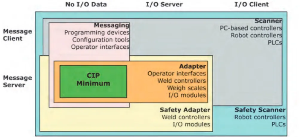
EtherNet/IP™ on TI’s Sitara™ processors February 2015 5 Texas Instruments アダプタは単純なデジタル入力デバイスの場合もあれば、モジュール式空気弁システムなど、 より複雑なデバイスの場合もあります。デフォルトでは、明示的メッセージ・サーバでもあります。 I/Oアダプタは、明示的メッセージを使用して、どのようなクラスのデバイスとでもピア・デー タを交換できますが、通信を開始することはできません。I/Oアダプタ形デバイスの例を次に示 します。 ◦PLCやその他のコントローラの要求に応じてリアルタイム・データを送受信する、 重量計、 溶接機、ドライブ、ロボットなど。 ◦コンピュータ・インターフェイス・カードやPLCとの間で、また各デバイス同士で明示的メッセー ジを送受信する、重量計、溶接機、ドライブ、ロボットなど。 ◦明示的またはリアルタイムI/OデータをPLCとの間で送受信するHMI製品。 I/OスキャナはI/Oアダプタとの暗黙的な通信を開始します。また、 確立する接続の構成や、 I/Oアダプタ・デバイスの構成方法などの問題を処理します。I/Oスキャナの一例としては、プ ログラマブル・コントローラが挙げられます。 図4には、メッセージング・オプションとデバイスの種類との関係を示します。各種のデバイスの 例もいくつか示しています。図の上部にある見出し(No I/O Data、I/O Server、I/O Client)は、 クライアント/サーバの役割と、暗黙的メッセージングが含まれるかどうか、含まれる場合はどの ような役割を果たしているかを示しています。 すべてのEtherNet/IPデバイスは、単純なデバイス識別および構成の要求に応答できるよう、最 小限の明示的メッセージ・サーバ機能を備えている必要があります(図4の“CIP Minimum”)。 明示的メッセージ・サーバ通信のみをサポートするデバイスと通信できるようにするには、明示的 メッセージ・クライアントが必要です。 明示的メッセージングと暗黙的メッセージングのどちらが適しているかは、通常は、通信の特性に よって判断できます。明示的メッセージングは簡単に実装できますが、要求/応答通信のような控 えめな性能要件に適しています。より高性能かつ決定性の高い通信には、暗黙的メッセージング が必要です。 図 4:EtherNet/IP 通信の種類とデバイスの分類
EtherNet/IP™ on TI’s Sitara™ processors February 2015
5
Texas Instruments
default it is also an explicit message server. I/O adapters can exchange peer data using explicit messages with any class of device but cannot originate relationships. Examples of I/O adapter type devices:
• Weigh scales, welders, drives and robots that send and receive real-time data at the request of PLCs and other controllers;
• Weigh scales, welders, drives and robots that send and receive explicit messages to and from com-puter interface cards, PLCs and each other; and,
• HMI products that send or receive explicit or real-time I/O data to/from PLCs.
• An I/O scanner initiates implicit communications with I/O adapters. It deals with issues such as configura-tion of which connecconfigura-tions to make, and how to configure the I/O adapter device. A programmable control-ler is an example of an I/O scanner
Figure 4 shows the relationship between messaging options and device types. A few examples of types of devices are also included. The headings across the top of the diagram (No I/O Data; I/O Server; and I/O Client) are references to client/server roles and whether or not implicit messaging is involved (and if so, what role it is playing).
All EtherNet/IP devices must have minimal Explicit Message Server capability so that they can respond to simple device identification and configuration requests (“CIP Minimum” in Figure 4). An Explicit Mes-sage Client is required to enable communication with a device that supports only explicit mesMes-sage server communications.
Understanding whether explicit or implicit messaging is appropriate normally depends on the nature of the communication. Explicit messaging is easier to implement but better suited for modest performance require-ments such as request/response communications. Implicit messaging is needed for higher performance and more deterministic communications.
Figure 4: EtherNet/IP communications types and device classifications
TI – EtherNet/IP white paper Manager, Tara Stratton (GolinHarris) Jack Shandle | [email protected] | (415) 601 8548 o Weigh scales, welders, drives and robots that send and receive real‐time data at the request of PLCs and other controllers; o Weigh scales, welders, drives and robots that send and receive explicit messages to and from computer interface cards, PLCs and each other; and, o HMI products that send or receive explicit or real‐time I/O data to/from PLCs. • An I/O scanner initiates implicit communications with I/O adapters. It deals with issues such as configuration of which connections to make, and how to configure the I/O adapter device. A programmable controller is an example of an I/O scanner Figure 4 shows the relationship between messaging options and device types. A few examples of types of devices are also included. The headings across the top of the diagram (No I/O Data; I/O Server; and I/O Client) are references client/server roles and whether or not implicit messaging is involved (and if so, what role it is playing). All EtherNet/IP devices must have minimal Explicit Message Server capability so that they can respond to simple device identification and configuration requests (“CIP Minimum” in Figure 4). An Explicit Message Client is required to enable communication with a device that supports only explicit message server communications. Figure 4. EtherNet/IP communications types and device classifications Understanding whether explicit or implicit messaging is appropriate normally depends on the nature of the communication. Explicit messaging is easier to implement but better suited modest performance requirements such as request/response communications. Implicit messaging is needed for higher performance and more deterministic communications OSI Model The protocol layers of EtherNet/IO can be mapped to the Open Systems Interconnection (OSI) model that characterizes and standardizes the internal functions of a communication system by partitioning it into abstraction layers. Understanding how CIP utilizes the Data Link, Network and Transport Layers are of particular interest because they affect the types and forms of CIP messaging. The Data Link Layer IEEE’s 802.3 specification is used to transmit data packets of data from device to device on the
EtherNet/IP™ on TI’s Sitara™ processors February 2015
EtherNet/IPのプロトコル層は、通信システムの内部機能を抽象化層に分割することによって特性
化と標準化を行う、OSI(Open Systems Interconnection)モデルに対応付けることができます。 データ・リンク層、ネットワーク層、トランスポート層はCIPメッセージングの種類や構造に影響 するため、これらの層をCIPでどのように利用しているか把握することが大切です。 IEEEの802.3仕様は、EtherNet/IPデータ・リンク層でデバイスからデバイスにデータ・パケット を送信するために使用されます。同じイーサネットCSMA/CDメディア・アクセスのメカニズムによっ て、ネットワーク上のデバイスが共通バス(ケーブルなど)を共有する方法や、データ衝突を検 出して対処する方法が決まります。 EtherNet/IPでは、ネットワーク層とトランスポート層でのメッセージングに、TCP/IPプロトコル・ スイートを利用しています。TCP/IPによって、IEEE仕様に欠けている、完全に機能的なネットワー クを実装するための通信プロトコル機能が利用できます。 すべてのCIPネットワークが使用するメッセージはカプセル化されるため、ネットワーク上のノード はイーサネット・メッセージ内にデータ部としてメッセージを埋め込むことができます。その後、ノー ドはそのメッセージ、つまり内部にメッセージが含まれたTCP/IPプロトコルをイーサネット・チップ (データ・リンク層)に送信します。EtherNet/IPでは、TCP/IPを使用することで明示的メッセー ジを送信できますが、このメッセージはノード間でクライアント・サーバ型のトランザクションを実 行するために使用されます。 EtherNet/IPでは、リアルタイム・メッセージング向けにUDPを採用し、送信先アドレス・グルー プへのマルチキャストと、I/Oデータ転送(暗黙的メッセージング)の実装を行っています。データ・ フィールドに含まれるのはリアルタイムI/Oデータのみで、プロトコル情報は含まれません。接続 の確立時にデータの意味は事前定義されているため、処理にかかる時間が最小になります。UDP メッセージは明示的メッセージに比べて小さく、より高速に処理できますが、UDPはコネクション レスであり、デバイスから他のデバイスへのデータ送信が保証されません。ただし、CIPの接続 プロセスでは、 信頼性の高い制御システムには欠かせない機能であるデータ配信の問題検出が 可能な、タイムアウト・メカニズムを利用できます。 EtherNet/IPでは、次に示す2つの形態のメッセージングを使用しています。 低頻度で優先度の低いメッセージ向けの未接続メッセージング。EtherNet/IPの未接続メッセー ジは、イーサネット上でメッセージを移動するためにTCP/IPリソースを使用します。 EtherNet/IPの接続メッセージングは、明示的メッセージの頻繁なトランザクションやリアルタイ ムのI/Oデータ転送のような特定の目的を持つそれぞれの専用ノード内でリソースを使用しま す。 接続を開くプロセスはコネクション・オリジネーションと呼ばれ、接続の確立要求を開始するノード はコネクション・オリジネーター、または単にオリジネーターと呼ばれます。反対に、その確立要 求に応答するノードはコネクション・ターゲット、またはターゲットと呼ばれます。
OSI
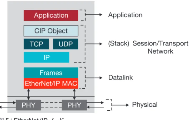
モデル ネットワーク層と トランスポート層 データ・リンク層EtherNet/IP™ on TI’s Sitara™ processors February 2015 7 Texas Instruments EtherNet/IPノードには、図5に示す修正OSIモデルに対応する4つの層があります。 物理層は、ネットワークを通じてビットストリーム・データを送信します。EtherNet/IPはイーサネッ トに完全対応しているため、100Mbit/sのデータ・レートをサポートする銅線または光ファイバのイー サネット対応ツイストペア・ケーブルなら、すべて使用できます。MAC層は、ASIC、FPGA、ま たは高速ファームウェアが動作するカスタム・ハードウェアという3つの方法のいずれかで実装で きます。ただし、 産業用アプリケーションには1つの制限があります。それは、 標準TCP/IPお よびUDP/IPスタックと、EtherNet/IPベースのデバイス・プロファイルをサポートする必要がある という点です。EtherNet/IPノード内では、ハードウェア、または組み込みCPUによって実装され るハードウェアとソフトウェアの組み合わせでアプリケーションを実行できます。 EtherNet/IPノードを実装する場合、設計者は3つの一般的なアーキテクチャからいずれかを選択 できます。 デバイスの機能を100%ハードウェア内に実装していてソフトウェアが不要な、コスト重視のアプ リケーションには、FPGAまたはASICを使用できます。このアーキテクチャを図6に示します。 より高い処理能力が必要な場合、たいていはオンチップのフラッシュ・メモリを備えた外部プロセッ サを追加することで実現できます。ASICまたはFPGAは、このアーキテクチャにおいても不可欠 な要素です(次ページの図7を参照)。センサー・アプリケーションでは、この種類のノードを頻 繁に利用します。プロセッサはセンサーを操作し、デバイス・ドライバを実装してEtherNet/IPプ ロトコル・スタックを実行します。さらにハードウェアを追加すると、単純なデジタルI/Oデバイス の実装に比べてコストが増加しますが、設計者にとってはニーズやコスト目標に見合ったプロセッ サを選択できるという利点もあります。
EtherNet/IP
ノード のコンポーネント 標準的なEtherNet/IP
ノード 図 5:EtherNet/IP ノード 図 6:基本的なデジタル I/O の EtherNet/IP ノードEtherNet/IP™ on TI’s Sitara™ processors February 2015
7
Texas Instruments
An EtherNet/IP node has four layers corresponding to the modified OSI model shown in Figure 5.
The physical layer transmits bitstream data through the network. Because EtherNet/IP is fully compat-ible with Ethernet, it can use any Ethernet-capable twisted-pair copper or fiber optic cabling that supports 100 Mbit/s data rates. The MAC layer can be implemented in one of three ways: an ASIC, FPGA, or, custom hardware running high-speed firmware. The industrial application has but one restriction. It must support a standard TCP/IP and UDP/IP stack and EtherNet/IP-based device profiles. Within the EtherNet/IP node, the application can run on hardware or a hardware/software combination implemented by an embedded CPU.
Designers have the choice of three common architectures when implementing an EtherNet/IP node. For cost-sensitive applications that do not require software because the device’s functionality is imple-mented 100% in hardware, an FPGA or ASIC can be used. This architecture is shown in Figure 6.
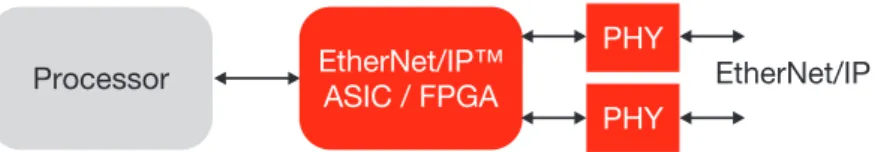
When more processing power is needed, it is frequently provided by the addition of an external processor with on-chip Flash memory. The ASIC or FPGA is still an integral part of the architecture (see Figure 7 on the following page). Sensor applications frequently utilize this type of node. The processor operates the sensor, implements the device driver and runs the EtherNet/IP protocol stack. The additional hardware increases cost compared to simple digital I/O device implementations but it also allows designers to select a processor that fits their needs and cost targets.
Components of an
EtherNet/IP node
Application CIP Object TCP IP Frames EtherNet/IP MAC UDP Application Datalink Physical (Stack) Session/Transport Network PHY PHYFigure 5: EtherNet/IP node
Typical
EtherNet/IP node
EtherNet/IP™ ASIC / FPGA PHY PHY EtherNet/IP Digital I/OFigure 6: Basic digital I/O EtherNet/IP node
EtherNet/IP™ on TI’s Sitara™ processors February 2015
7
Texas Instruments
An EtherNet/IP node has four layers corresponding to the modified OSI model shown in Figure 5.
The physical layer transmits bitstream data through the network. Because EtherNet/IP is fully compat-ible with Ethernet, it can use any Ethernet-capable twisted-pair copper or fiber optic cabling that supports 100 Mbit/s data rates. The MAC layer can be implemented in one of three ways: an ASIC, FPGA, or, custom hardware running high-speed firmware. The industrial application has but one restriction. It must support a standard TCP/IP and UDP/IP stack and EtherNet/IP-based device profiles. Within the EtherNet/IP node, the application can run on hardware or a hardware/software combination implemented by an embedded CPU.
Designers have the choice of three common architectures when implementing an EtherNet/IP node. For cost-sensitive applications that do not require software because the device’s functionality is imple-mented 100% in hardware, an FPGA or ASIC can be used. This architecture is shown in Figure 6.
When more processing power is needed, it is frequently provided by the addition of an external processor with on-chip Flash memory. The ASIC or FPGA is still an integral part of the architecture (see Figure 7 on the following page). Sensor applications frequently utilize this type of node. The processor operates the sensor, implements the device driver and runs the EtherNet/IP protocol stack. The additional hardware increases cost compared to simple digital I/O device implementations but it also allows designers to select a processor that fits their needs and cost targets.
Components of an
EtherNet/IP node
Application CIP Object TCP IP Frames EtherNet/IP MAC UDP Application Datalink Physical (Stack) Session/Transport Network PHY PHYFigure 5: EtherNet/IP node
Typical
EtherNet/IP node
EtherNet/IP™ ASIC / FPGA PHY PHY EtherNet/IP Digital I/OEtherNet/IP™ on TI’s Sitara™ processors February 2015 8 Texas Instruments EtherNet/IPアプリケーションの実装方法として一般的な3つ目のアーキテクチャでは、EtherNet/ IPノードを、内蔵CPUを備えたデバイスのペリフェラルの1つにします。このアーキテクチャを 図8に示します。プロセッサは、FPGAの使用可能なゲートを使って構成できます。FPGAを使っ たもう1つの選択肢に、内蔵プロセッサを備えたFPGAを使用するという方法があります。これ と同じように、ASICベンダーは、 デバイス上でEtherNet/IPとプロセッサを統合しています。 FPGAの実装には柔軟性という利点がある一方で欠点もあり、FPGAで使用できるプロセッサに よってはコストまたは動作周波数の目標を達成できない可能性があります。
テキサス・インスツルメンツ(TI)では、EtherNet/IP機能をSitara™ AM335x ARM® Cortex®-A8
プロセッサに統合しました。これらのデバイスは、ペリフェラルやインターフェイスが高度に集積 されているため、 産業用オートメーション・アプリケーションに最適です。 さらに、Sitara
AM437x ARM Cortex-A9プロセッサは、EtherNet/IP機能をオンチップで統合するために必要な
すべてのリソースを備えています。
Sitara AM33xおよびAM437xプロセッサには、MIIインターフェイスとの非常に低いレベルでの
やり取りをサポートする、プログラマブル・リアルタイム・ユニット(PRU)サブシステムが含ま れているため、EtherNet/IPを簡単に実装できます。TIが既にEtherNet/IPを統合している
AM335xでは、イーサネットMAC層の全体がファームウェアを介してPRUサブシステムにカプ
セル化されています。
処理効率を高めるため、EtherNet/IPノードはそのノードにアドレシングされたパケットのみを処理 し、それ以外のフレームをすべて次のデバイスに転送します。アプリケーションや、EtherNet/IP スタック(第7層)を実行しているARMプロセッサとの通信は、割り込みを利用することで実現 できます。EtherNet/IPをSitaraプロセッサに統合すると、低レベルの高速EtherNet/IP機能(DLR
およびPTP/1588)のほぼすべてがPRUサブシステムによって処理されます。この場合、ARM
プロセッサは、スタックや、モーター制御などの複雑なアプリケーションの実行に、 処理能力の 大部分を割り当てることができます。
TIのTLK110のようなイーサネットPHYデバイスによって、TIのSitara EtherNet/IPソリューショ
ンが完成します。TLK110は、重要な性能属性である、MIIおよびPHYインターフェイス間の低 レイテンシ向けに最適化されています。また、TLK110は、ケーブル障害の位置をすばやく特定 できる、高度なケーブル診断機能も備えています。 テキサス・インスツルメンツの
EtherNet/IP
ソリューション 図 7:ASIC と外部プロセッサを備えた EtherNet/IP 図 8:内蔵 EtherNet/IP とプロセッサEtherNet/IP™ on TI’s Sitara™ processors February 2015
8 Texas Instruments
The third common architecture for implementing EtherNet/IP applications turns the EtherNet/IP node into one of the peripherals in a device with an integrated CPU. This architecture is shown in Figure 8. The processor may be configured using available gates in an FPGA. Another option available with some FPGAs is to use one with an integrated processor. Similarly, ASIC vendors have integrated EtherNet/IP and a proces-sor on their device. FPGA implementations offer the advantage of being flexible but have a downside as well because of the possibility of not meeting cost or operating frequency targets depending on the processor available on the FPGA.
Texas Instruments (TI) has integrated EtherNet/IP functionality into its Sitara™ AM335x ARM® Cortex®-A8 processors. These devices are highly integrated with peripherals and interfaces that make them ideal for industrial automation applications. In addition, the Sitara AM437x ARM Cortex-A9 processors have been equipped with all of the resources needed to integrate EtherNet/IP capabilities on-chip.
The Sitara AM33x and AM437x processors include the programmable real-time unit (PRU) subsys-tem, which supports very low-level interaction with the MII interfaces and, therefore, can easily implement EtherNet/IP. On the AM335x, where TI has already integrated EtherNet/IP, the entire Ethernet MAC layer is encapsulated in the PRU subsystem through firmware.
As a processing efficiency measure, EtherNet/IP nodes process only those packets that are addressed to them and forward all other frames to the next device. Communication with the application and the ARM processor running the EtherNet/IP stack (Layer 7) is accomplished by using interrupts. When EtherNet/IP is integrated into a Sitara processor, almost all of the low-level, high-speed EtherNet/IP functionality (DLR and PTP/1588) is handled by the PRU subsystem. When this is the case, the ARM processor can allocate almost all of is processing power to running the stack and complex applications such as motor control.
Ethernet PHY devices such as TI’s TLK110 complete TI’s Sitara EtherNet/IP solutions. The TLK110 is opti-mized for low latency between the MII and PHY interfaces, which is an important performance attribute. The TLK110 also has advanced cable diagnostics features that can quickly locate cable faults.
PHY PHY EtherNet/IP™
ASIC / FPGA
Processor EtherNet/IP
Figure 7: EtherNet/IP with ASIC and external processor
EtherNet/IP™ ASIC / FPGA PHY PHY EtherNet/IP ARM /Proprietary Processor ®
Figure 8: Integrated EtherNet/IP with processor
EtherNet/IP solutions
from Texas Instruments
EtherNet/IP™ on TI’s Sitara™ processors February 2015
9
Texas Instruments
Sitara AM335xおよびAM437xプロセッサは、それぞれARM Cortex-A8コアとARM Cortex-A9
RISCコアをベースにした低電力デバイスです。どちらのプロセッサも、多様な内蔵ペリフェラル を備えています。Sitaraプロセッサは、 単純なアプリケーション用の300MHzから、 産業用ドラ イブなどの高い性能を必要とする複雑なアプリケーション用の1GHzまで、産業用アプリケーショ ン向けに複数の動作周波数をサポートしています。AM335xおよびAM437xプロセッサは、どち
らもEtherNet/IPをあらゆる性能レベルで実装できます。AM335xプロセッサは、1個のPRUコ
プロセッサ(2個のリアルタイム・コア)で構成されていますが、一方でAM437xプロセッサは2 個のPRU(合計で4個のリアルタイム・コア)を搭載しています。Sitara AM335xおよび
AM437xプロセッサのブロック図を、以下の図9と図10に示します。オンチップのペリフェラル
や各機能など、両デバイスのその他の情報については、www.ti.com/am335xおよびwww.
ti.com/am437xを参照してください。
Sitara
プロセッサのブロック図
図 9:TI の Sitara™ AM335x ARM® Cortex®-A8 プロセッサのブロック図
図 10:TI の Sitara AM437x ARM Cortex-A9 プロセッサのブロック図
(1)TSCを使用すると、1 つの ADC で使用できるチャネルが制限されます。 (2)最大クロック:LPDDR2=266MHz、DDR3=400MHz
*800MHz/1GHz は、15×15 パッケージでのみ使用可能。13×13 パッケージでは、最大 600MHz までサポートします。 (1)TSCを使用すると、使用できる ADC チャネルが制限されます。
EtherNet/IP™ on TI’s Sitara™ processors February 2015
9
Texas Instruments
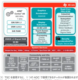
The Sitara AM335x and AM437x processors are low-power devices based on the ARM Cortex-A8 and ARM Cortex-A9 RISC cores, respectively. Both processors feature a broad range of integrated peripherals. For industrial applications, the Sitara processors support multiple operating frequency ranges from 300 MHz for simple applications up to 1 GHz for complex applications that require high performance, such as industrial drives. Both the AM335x and AM437x processors at any performance level can implement EtherNet/IP. The AM335x processor is configured with one PRU coprocessor (two real-time cores) while the AM437x processor features two PRUs for a total of four real-time cores. The block diagrams of the Sitara AM335x and AM437x processors are shown in Figures 9 and 10 below. Additional information on both devices, including their on-chip peripherals and features, is available at www.ti.com/am335x and www.ti.com/am437x.
Sitara processors
block diagram
Figure 9: Block diagram of TI’s Sitara™ AM335x ARM® Cortex®-A8 processor
ARM Cortex -A9 ® ® 800 MHz, 1 GHz Graphics Acceleration SGX530 Quad-Core PRU-ICSS System Services
Connectivity and I/Os
Security AccelerationPac Display Subsystem 32K/32K L1 45 nm Industrial Communication Subsystem EtherCAT , PROFINET , EtherNet/IP™ + Motor feedback protocols + Sigma Delta ® ® 24-Bit LCD Processing Overlay, Resizing, Color Space Conversion, etc. Touch Screen Controller 256K L2/L3 64K RAM EDMA WDT RTC NAND/ NOR (16-Bit ECC) 3 MMC/ SD/SDIO McASP ×2 GPIO UART ×6 PWM ×6 CAN ×2 Camera I/F (2× Parallel) EMAC 2-Port Switch 10/100/1G w/ 1588 OTG +USB2 PHY ×2 HDQ QSPI eCAP/ eQEP ×3 SPI ×5 I C ×32 2 12-Bit ADCs Debug 12 Timers SyncTimer 32K
Simple Pwr Seq
256KB L3 Shared RAM 32-Bit
LPDDR2/DDR3/DDR3L Crypto, Secure Boot
Figure 10: Block diagram of TI’s Sitara AM437x ARM Cortex-A9 processor. (1)Use of TSC will limit availability of channels on one ADC. (2)Max clock: LPDDR2=266 MHz; DDR3=400 MHz. ARM Cortex -A8 ® ® Up to 1 GHz* Graphics AccelerationPac SGX530 PRU System Services
Connectivity and I/Os
Security AccelerationPac LCD Controller 32K/32K L1 45 nm Industrial Communication Subsystem EtherCAT , PROFINET , EtherNet/IP™ ® ® 24-Bit LCD Cont. Touch Screen Controller(1) 256K L2 w/ ECC 64K RAM EDMA WDT RTC NAND/ NOR (16-Bit ECC) MMC/ SD/SDIO ×3 McASP ×2 GPIO UART ×6 PWM ×3 EMAC 2-Port w/ Switch 10/100/1G w/ 1588 USB2 OTG + PHY ×2 CAN ×2 eCAP/ eQEP ×3 SPI ×2 I C ×32 12-Bit ADC(1) JTAG/ETB Timers ×8 64KB L3 Shared RAM LPDDR1/DDR2/ DDR3/DDR3L Crypto
* 800 MHz / 1 GHz only available on 15×15 package. 13×13 package supports up to 600 MHz.
(1) Use of TSC will limit available ADC channels.
EtherNet/IP™ on TI’s Sitara™ processors February 2015
9
Texas Instruments
The Sitara AM335x and AM437x processors are low-power devices based on the ARM Cortex-A8 and ARM Cortex-A9 RISC cores, respectively. Both processors feature a broad range of integrated peripherals. For industrial applications, the Sitara processors support multiple operating frequency ranges from 300 MHz for simple applications up to 1 GHz for complex applications that require high performance, such as industrial drives. Both the AM335x and AM437x processors at any performance level can implement EtherNet/IP. The AM335x processor is configured with one PRU coprocessor (two real-time cores) while the AM437x processor features two PRUs for a total of four real-time cores. The block diagrams of the Sitara AM335x and AM437x processors are shown in Figures 9 and 10 below. Additional information on both devices, including their on-chip peripherals and features, is available at www.ti.com/am335x and www.ti.com/am437x.
Sitara processors
block diagram
Figure 9: Block diagram of TI’s Sitara™ AM335x ARM® Cortex®-A8 processor
ARM Cortex -A9 ® ® 800 MHz, 1 GHz Graphics Acceleration SGX530 Quad-Core PRU-ICSS System Services
Connectivity and I/Os
Security AccelerationPac Display Subsystem 32K/32K L1 45 nm Industrial Communication Subsystem EtherCAT , PROFINET , EtherNet/IP™ + Motor feedback protocols + Sigma Delta ® ® 24-Bit LCD Processing Overlay, Resizing, Color Space Conversion, etc. Touch Screen Controller 256K L2/L3 64K RAM EDMA WDT RTC NAND/ NOR (16-Bit ECC) 3 MMC/ SD/SDIO McASP ×2 GPIO UART ×6 PWM ×6 CAN ×2 Camera I/F (2× Parallel) EMAC 2-Port Switch 10/100/1G w/ 1588 OTG +USB2 PHY ×2 HDQ QSPI eCAP/ eQEP ×3 SPI ×5 I C ×32 2 12-Bit ADCs Debug 12 Timers SyncTimer 32K
Simple Pwr Seq
256KB L3 Shared RAM 32-Bit
LPDDR2/DDR3/DDR3L Crypto, Secure Boot
Figure 10: Block diagram of TI’s Sitara AM437x ARM Cortex-A9 processor. (1)Use of TSC will limit availability of channels on one ADC. (2)Max clock: LPDDR2=266 MHz; DDR3=400 MHz. ARM Cortex -A8 ® ® Up to 1 GHz* Graphics AccelerationPac SGX530 PRU System Services
Connectivity and I/Os
Security AccelerationPac LCD Controller 32K/32K L1 45 nm Industrial Communication Subsystem EtherCAT , PROFINET , EtherNet/IP™ ® ® 24-Bit LCD Cont. Touch Screen Controller(1) 256K L2 w/ ECC 64K RAM EDMA WDT RTC NAND/ NOR (16-Bit ECC) MMC/ SD/SDIO ×3 McASP ×2 GPIO UART ×6 PWM ×3 EMAC 2-Port w/ Switch 10/100/1G w/ 1588 USB2 OTG + PHY ×2 CAN ×2 eCAP/ eQEP ×3 SPI ×2 I C ×32 12-Bit ADC(1) JTAG/ETB Timers ×8 64KB L3 Shared RAM LPDDR1/DDR2/ DDR3/DDR3L Crypto
* 800 MHz / 1 GHz only available on 15×15 package. 13×13 package supports up to 600 MHz.
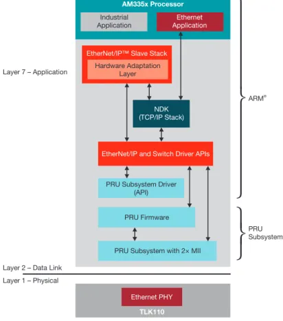
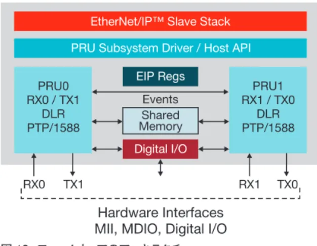
EtherNet/IP™ on TI’s Sitara™ processors February 2015 図11に示すように、TI Sitaraデバイス上のEtherNet/IPスレーブの実装は、次の3つのソフトウェ ア・コンポーネントで構成されます。(1)PRU内でレイヤ2の機能を実装するマイクロコード、(2) ARMプロセッサで動作するEtherNet/IPスレーブ・スタック、(3)産業用アプリケーション。TI では、プロトコル・アダプテーション層やデバイス・ドライバなど、追加のサポート・コンポーネン トをソフトウェア開発キット内で提供しています。 TIとサードパーティ・ソフトウェア・ベンダーが密接に協力し合うことにより、Sitara AM335xプ ロセッサ上でサードパーティのEtherNet/IPスレーブ・スタック・コードを徹底的に検証できました。 ユーザーは、製品の市場投入前にサードパーティに問い合わせを行い、このスタックのライセン ス契約を交わすことになります。 ファームウェアのアーキテクチャを、次ページの図12に示します。
EtherNet/IPをSitaraプロセッサに統合する場合、PRUはMAC学習、ストーム防止、 パケット
統計などの機能を含む基本的なイーサネット・スイッチ・プロトコルを実装します。各PRUを構成 している2つのリアルタイム・コアは、それぞれが独立して2つの物理ポートを制御します。図 に示すように、各PRUコアが1組のRX/TXを制御します。PRUコアは、特別な命令セットや共 有メモリを使用して相互に通信し、協調関係を確認します。TIの産業用通信サブシステム(ICSS) アーキテクチャによって、 構成可能なパラメータに基づく、ポート間での低レイテンシのストア・ アンド・フォワードが可能になります。また、PRUには、ARMプロセッサの実行に対してリアル タイムで割り込みを行うことで、決定性の処理を保証する機能もあります。
EtherNet/IP
ソフトウェア・ アーキテクチャ ファームウェア 図 11:EtherNet/IP スレーブのソフトウェア・アーキテクチャEtherNet/IP™ on TI’s Sitara™ processors February 2015
As shown in Figure 11, three software components will comprise EtherNet/IP slave implementations on TI Sitara devices: (1) microcode that implements Layer 2 functionality in the PRU; (2) the EtherNet/IP slave stack that runs on the ARM processor; and (3) the industrial application. TI provides additional supporting components such as the protocol adaptation layer and device drivers in its software development kit.
A close collaboration between TI and a third-party software vendor has resulted in complete validation of the third-party’s EtherNet/IP Slave Stack Code on the Sitara AM335x processors. Users are expected to contact the third party to license the stack prior to marketing their product.
The firmware architecture is shown in Figure 12 on the following page.
When EtherNet/IP is integrated into a Sitara processor, the PRU implements basic Ethernet switch pro-tocols including features such as MAC learning, storm prevention and packet statistics. The two real-time cores that make up each PRU are independently responsible for controlling the two physical ports. Each PRU core is responsible for one RX/TX combination as shown in the diagram. The PRU cores communicate with each other to ensure coordination using a set of special instructions and shared memory. TI’s Industrial Com-munications Subsystem (ICSS) architecture allows low latency store and forward between the ports based on configurable parameters. PRUs also have the ability to interrupt ARM processor execution in real time to ensure deterministic processing.
AM335x Processor
Industrial Application
Ethernet Application
EtherNet/IP™ Slave Stack
EtherNet/IP and Switch Driver APIs
PRU Subsystem Driver (API)
PRU Firmware
PRU Subsystem with 2× MII
Ethernet PHY
TLK110
Layer 2 – Data Link Layer 7 – Application ARM® PRU Subsystem Layer 1 – Physical NDK (TCP/IP Stack) Hardware Adaptation Layer
Figure 11: Software architecture for EtherNet/IP slave
EtherNet/IP software
architecture
EtherNet/IP™ on TI’s Sitara™ processors February 2015
11
Texas Instruments
図 12:ファームウェアのアーキテクチャ
EtherNet/IPは、その主な役割である基本イーサネット上でのスタック機能セットの実行だけでなく、
他にも2つの重要な機能を実行します。2つの機能とは、Device Level Ring(DLR)と呼ばれる リング型冗長プロトコルと、PTP/1588と呼ばれるデバイス間の高精度時刻同期のためのIEEE標
準です。Sitaraプロセッサに統合する場合、PRUはこれらの機能を両方とも実装します。PRUは、
その決定性のリアルタイム処理能力によって、これらのフレームを非常に低いレイテンシで処理で きます。メインのステート・マシンはPRU上にありますが、DLRおよびPTP/1588の実行に必要 なステート・マシンには、ARMプロセッサも部分的に関与しています。
TIのEtherNet/IP内蔵プロセッサであるSitara AM335xプロセッサは、TIのTLK110イーサネット
PHYデバイスによってレイテンシが2μsを下回り、優れたEtherNet/IPスレーブ・ソリューション の仲間入りを果たしています。
TIでは、SitaraプロセッサによってEtherNet/IPを簡単に統合できるようにしています。EtherNet/
IPスレーブを統合するために必要なツールやソフトウェア・コードは、すべてがSitara産業用ソフ トウェア開発キット(SDK)の一部として利用できます。これには、EtherNet/IPプロトコル用のファー ムウェア、ソフトウェア・ドライバ、 ハードウェア初期化ルーチン、スタック・アプリケーション・ プログラミング・インターフェイス(API)用のアダプテーション層、EtherNet/IPプロトコル・スタッ ク、 およびアプリケーション自体が含まれています。SDKには、ユーザーがアプリケーションを 変更したり新しい機能を組み込んだりするために役立つサポート・ドキュメントが付属します。
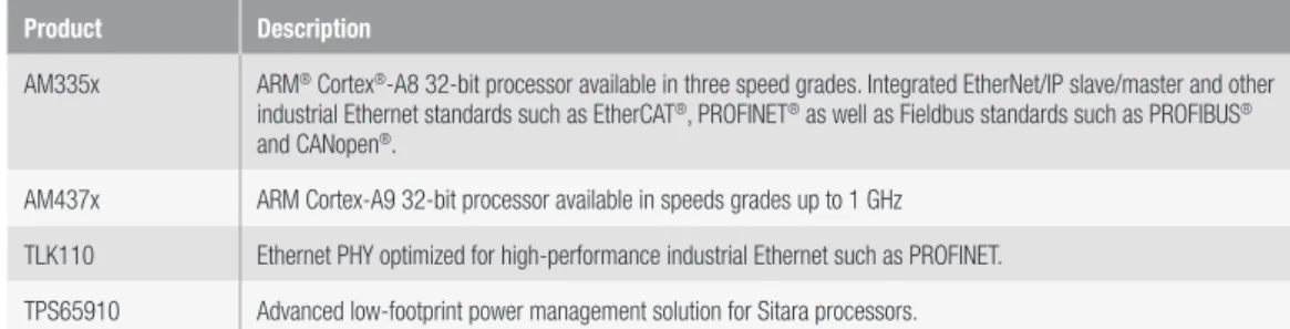
TIの一部のSitara ARMプロセッサは、EtherNet/IPを実装できます。TIでは、 信号チェーンや
電力回路向けの補完用アナログ製品も提供しています。次ページの表2には、このような製品の 概要を示します。
DLR
およびPTP/1588
簡単なEtherNet/IP
の統合EtherNet/IP
実装のためのデバイスEtherNet/IP™ on TI’s Sitara™ processors February 2015
11
Texas Instruments
EtherNet/IP™ Slave Stack PRU Subsystem Driver / Host API PRU0 RX0 / TX1 DLR PTP/1588 PRU1 RX1 / TX0 DLR PTP/1588 EIP Regs RX0 RX1 Hardware Interfaces MII, MDIO, Digital I/O
TX1 TX0 Shared
Memory Digital I/O
Events
Figure 12: Firmware architecture
In addition to its primary mission of running a set of stack features on top of basic Ethernet, EtherNet/IP executes two other valuable features: A ring redundancy protocol known as Device Level Ring (DLR) and an IEEE standard for high accuracy time synchronization across devices known as PTP/1588. When integrated into a Sitara processor, the PRU implements both these features. Thanks to its deterministic real-time processing capabilities, the PRU processes these frames with very low latency. While the main state machine is on the PRU, the ARM processor is also partially involved in the state machine required to execute DLR and PTP/1588.
TI’s integrated EtherNet/IP processor, the Sitara AM335x processor, with TI’s TLK110 Ethernet PHY device has a latency of less than 2 µs, which places it among the leading EtherNet/IP slave solutions.
TI is making it easy to integrate EtherNet/IP with its Sitara processors. All of the tools and software code required to integrate EtherNet/IP slaves are available as part of the Sitara industrial software development kit (SDK), which includes firmware for the EtherNet/IP protocol, software drivers, hardware initialization routines, an adaptation layer for the stack application programming interface (API), EtherNet/IP protocol stack and the application itself. The SDK comes with supporting documentation that will help users modify and build new features into applications.
Several of TI’s Sitara ARM processors are capable of implementing EtherNet/IP. TI also offers complemen-tary analog products for the signal chain and power circuitry. Table 2 on the following page provides a brief overview of these products.