1.は じ め に
環境問題に対する関心やエネルギー問題を中心とした 節電ニーズがますます高まっており,一般のポンプにお いても消費電力削減のために省エネルギー化の動きが加 速している。ポンプの省エネルギー化手段としては,イン バータによる可変速運転が広く知られている。これは ポンプの必要動力が回転速度の3乗に比例して減少する からである。すなわち,ポンプの回転速度を80%にした 場合,動力は約半分となり,ポンプの可変速駆動によっ て大きな省エネルギー効果が期待できる。しかし,圧倒 的に稼動台数の多い小中型のポンプ使用現場では,用途 の多様性と対策の手間を考えるとまだまだ省エネルギー 化が定着しているとは言い難い。 そこで,ポンプの可変速駆動用インバータに,ポンプ の負荷用途に合わせた各種最適運転制御機能を組合せた ポンプ専用多機能可変速ドライバEVFC型(EVFC型は 当社の機種記号である,以下同様)を開発したので,そ の概要を紹介する(写真1)。2.特 長
EVFC型はポンプの省エネルギー,高効率運転をユー ザが積極的に取り組むことができる各種機能を搭載した ポンプ専用のインバータ(可変速ドライバ)である。 2-1 駆動対象モータ ポンプ駆動用モータとしては誘導モータが長年主流で あったが,より高効率で小型化が可能な永久磁石同期 モータ(Permanent Magnet Synchronous Motor,以下 PMモータ)によって運転される機会が増えている。 一般に,PMモータの駆動には回転子の磁極位置を把ポンプ専用多機能可変速ドライバ
駒 井 正 和
*畑 林 希 美
*塚 越 健 太
* * 風水力機械カンパニー 技術生産統括 開発統括部 制御装 置開発設計室 VFDグループ 写真 1 多機能可変速ドライバ(EVFC型)Photo 1 Multifunctional variable speed driver (Model EVFC)
13-43 01/239
Multifunctional variable speed driver for pumps
by Masakazu KOMAI, Kimi HATABAYASHI, & Kenta TSUKAKOSHI
A multifunctional variable speed driver (Model EVFC) has been developed that allows users to willingly and easily achieve energy savings in pump operations.
Model EVFC provides variable speed motor drive control for both induction motors and efficient permanent magnet synchronous motors. It also supports optimum pump control (including pressure and flow controls), multi-pump control, and many pump protection functions based on Ebara’s long-standing expertise.
Thus, model EVFC allows users to achieve energy savings in pump operations and to ensure suitable operation and protection for each application.
Keywords: Variable speed drive, Energy saving, Optimum pump control, Permanent magnet synchronous motor, Sensorless vector control, Motor mount, Multi-pump control, External communication function, Pump protection
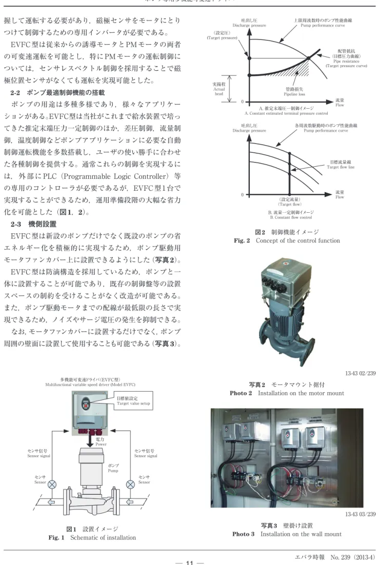
握して運転する必要があり,磁極センサをモータにとり つけて制御するための専用インバータが必要である。 EVFC型は従来からの誘導モータとPMモータの両者 の可変速運転を可能とし,特にPMモータの運転制御に ついては,センサレスベクトル制御を採用することで磁 極位置センサがなくても運転を実現可能とした。 2-2 ポンプ最適制御機能の搭載 ポンプの用途は多種多様であり,様々なアプリケー ションがある。EVFC型は当社がこれまで給水装置で培っ てきた推定末端圧力一定制御のほか,差圧制御,流量制 御,温度制御などポンプアプリケーションに必要な自動 制御運転機能を多数搭載し,ユーザの使い勝手に合わせ た各種制御を提供する。通常これらの制御を実現するに は,外 部 に PLC(Programmable Logic Controller) 等 の専用のコントローラが必要であるが,EVFC 型1台で 実現することができるため,運用準備段階の大幅な省力 化を可能とした(図1,2)。 2-3 機側設置 EVFC型は新設のポンプだけでなく既設のポンプの省 エネルギー化を積極的に実現するため,ポンプ駆動用 モータファンカバー上に設置できるようにした(写真2)。 EVFC型は防滴構造を採用しているため,ポンプと一 体に設置することが可能であり,既存の制御盤等の設置 スペースの制約を受けることがなく改造が可能である。 また,ポンプ駆動モータまでの配線が最低限の長さで実 現できるため,ノイズやサージ電圧の発生を抑制できる。 なお,モータファンカバーに設置するだけでなく,ポンプ 周囲の壁面に設置して使用することも可能である(写真 3)。 上限周波数時のポンプ性能曲線
Pump performance curve
流量 Flow 吐出し圧 Discharge pressure 配管抵抗 (目標圧力曲線) Pipe resistance (Target pressure curve)
0 0 実揚程 Actual head A. 推定末端圧一制御イメージ
A. Constant estimated terminal pressure control
(設定圧)
(Target pressure)
目標流量線
Target flow line
(設定流量)
(Target flow)
各周波数駆動時のポンプ性能曲線
Pump performance curve
B. 流量一定制御イメージ
B. Constant flow control
流量 Flow 吐出し圧 Discharge pressure 管路損失 Pipeline loss 図 2 制御機能イメージ
Fig. 2 Concept of the control function
電力 Power センサ Sensor センサ Sensor ポンプ Pump 多機能可変速ドライバ(EVFC型)
Multifunctional variable speed driver (Model EVFC)
センサ信号
Sensor signal
センサ信号
Sensor signal
目標値設定
Target value setup
図 1 設置イメージ
Fig. 1 Schematic of installation
写真 2 モータマウント据付
Photo 2 Installation on the motor mount
13-43 02/239
写真 3 壁掛け設置
Photo 3 Installation on the wall mount
ニタを行うことができる(図5)。 2-6 ポンプ保護機能 汎用インバータに搭載の電圧・電流・温度などの通常 の保護機能だけでなく,ポンプに関する保護機能も充実 させ,トータルで信頼性の高いシステムを提供している。 主なポンプ保護機能を次に示す。 ・ ポンプ始動過多:一定時間内のポンプ始動回数を制 限し,始動過多によるポンプ及び配管系,モータへ 2-4 複数台連携運転 ポンプの並列運転制御を実現するための複数台運転機 能を装備している。複数台運転としては,ポンプごとに EVFC 型を接続した全台インバータ制御と,ポンプ1台 だけを可変速制御し,その他のポンプをEVFC型のリレー 出力で制御する1台インバータ制御の 2 つの制御方式を 提供している。 全台インバータ制御は,最大5台までのEVFC型同士 をシリアル通信で接続して,圧力センサ信号などを1台 に入力することで,複数台ポンプを使用した自動可変速 制御運転ができる(図3)。 1台インバータ制御は,EVFC型のリレー出力により, モータポンプと電源間に接続したマグネットスイッチを ON / OFFすることで,最大3台までの簡易的な複数台 運転が可能である(図4)。 2-5 外部通信機能 外部からEVFC型の自動制御,省エネルギー効果のモ ニタリングを実現するため,外部通信機能を装備してい る。この機能により,外部に設けられたPCやPLCといっ た中央監視装置からの通信によって,ポンプの制御やモ 圧力タンク
Tank Pressure signal圧力信号
電力 Power 電力 Power 電力 Power 電力 Power 電力 Power シ リ ア ル 通信信号
Serial communication signal
図 3 複数台制御(全台インバータ方式)
Fig. 3 Multi-pump control (method of all inverters)
圧力タンク
Tank Pressure signal圧力信号
電力 Power 電力 Power 電力 Power 電磁接触器 Magnet switch電磁接触器 Magnet switch 電磁接触器 Magnet switch 図 4 複数台制御(1台インバータ方式)
Fig. 4 Multi-pump control (method of single inverter)
Modbus
給水ユニット
Feed-water pump unit
水位センサ
Water level sensor
マスタ−スレーブ通信
Master - slave communication
マスタ Master スレーブ Slave 外部通信 External communication PC or PLC 図 5 外部通信機能
0 0 10 20 30 40 50 60 8 6 4 2 0 50 100 150 200 250 300 350 0 0 10 20 30 40 50 60 8 6 4 2 0 50 100 150 200 250 300 350 全揚程 Total head 吐出し量 Capacity[l/min] 全揚程 Total head [cm] 消費電力 Power consumption [kW] 電流 Output current 消費電力 Output power 流量 Flow 全揚程 Total head 吐出し量 Capacity[L/min] 全揚程 Total head [m] 消費電力 Power consumption [kW] 電流 Output current 消費電力 Output power 流量 Flow 電流 Current [A] 電流 Current [A] 図 7 リミットロード運転例
Fig. 7 Example of limit load operation
ポンプ性能曲線
Pump performance curve
制限時性能曲線 Limited performance curve 0 制限電流値 /制限電力
Limit current value /Limit power value
出力電流 or 消費電力
Output current or power
回転速度 Rotational speed 0 0 制限値を超えないように 回転速度を制御
Rotational speed is controlled not to exceed the limiting value.
吐出し圧 Discharge pressure 流量 Flow 流量 Flow 流量 Flow 図 6 リミットロード運転機能
Fig. 6 Limit load operation function
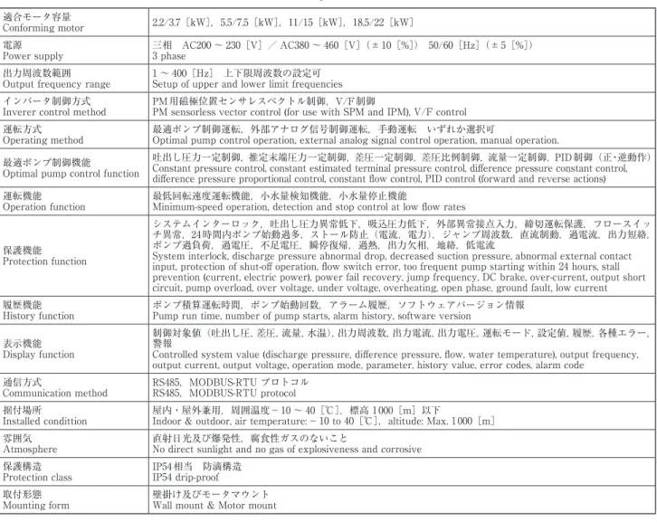
適合モータ容量
Conforming motor 2.2/3.7[kW],5.5/7.5[kW],11/15[kW],18.5/22[kW] 電源
Power supply 三相 AC200 ~ 230[V]/ AC380 ~ 460[V](±10[%]) 50/60[Hz](±5[%])3 phase 出力周波数範囲
Output frequency range 1 ~ 400[Hz] 上下限周波数の設定可Setup of upper and lower limit frequencies インバータ制御方式
Inverer control method PM用磁極位置センサレスベクトル制御,V/F制御PM sensorless vector control (for use with SPM and IPM), V/F control 運転方式
Operating method 最適ポンプ制御運転,外部アナログ信号制御運転,手動運転 いずれか選択可Optimal pump control operation, external analog signal control operation, manual operation. 最適ポンプ制御機能
Optimal pump control function
吐出し圧力一定制御,推定末端圧力一定制御,差圧一定制御,差圧比例制御,流量一定制御,PID制御(正・逆動作) Constant pressure control, constant estimated terminal pressure control, difference pressure constant control, difference pressure proportional control, constant flow control, PID control (forward and reverse actions) 運転機能
Operation function 最低回転速度運転機能,小水量検知機能,小水量停止機能Minimum-speed operation, detection and stop control at low flow rates
保護機能 Protection function
システムインターロック,吐出し圧力異常低下,吸込圧力低下,外部異常接点入力,締切運転保護,フロースイッ チ異常,24時間内ポンプ始動過多,ストール防止(電流,電力),ジャンプ周波数,直流制動,過電流,出力短絡, ポンプ過負荷,過電圧,不足電圧,瞬停復帰,過熱,出力欠相,地絡,低電流
System interlock, discharge pressure abnormal drop, decreased suction pressure, abnormal external contact input, protection of shut-off operation, flow switch error, too frequent pump starting within 24 hours, stall prevention (current, electric power), power fail recovery, jump frequency, DC brake, over-current, output short circuit, pump overload, over voltage, under voltage, overheating, open phase, ground fault, low current 履歴機能
History function ポンプ積算運転時間,ポンプ始動回数,アラーム履歴,ソフトウェアバージョン情報Pump run time, number of pump starts, alarm history, software version 表示機能
Display function
制御対象値(吐出し圧,差圧,流量,水温),出力周波数,出力電流,出力電圧,運転モード,設定値,履歴,各種エラー, 警報
Controlled system value (discharge pressure, difference pressure, flow, water temperature), output frequency, output current, output voltage, operation mode, parameter, history value, error codes, alarm code
通信方式
Communication method RS485,MODBUS-RTU プロトコルRS485,MODBUS-RTU protocol 据付場所
Installed condittion 屋内・屋外兼用,周囲温度−10 ~ 40[℃],標高 1000[m]以下Indoor & outdoor, air temperature:−10 to 40[℃],altitude: Max. 1000[m] 雰囲気
Atmosphere 直射日光及び爆発性,腐食性ガスのないことNo direct sunlight and no gas of explosiveness and corrosive 保護構造
Protection class IP54相当 防滴構造IP54 drip-proof 取付形態
Mounting form 壁掛け及びモータマウントWall mount & Motor mount
表 仕様一覧