電波干渉計の原理と
超長基線電波干渉計
電波干渉計の原理と
電波干渉計の原理と
超長基線電波干渉計
超長基線電波干渉計
National Institute of Information
and Communications Technology
National Institute of Information
National Institute of Information
and Communications Technology
Young
Young
’
’
s
s
Experiment
Experiment
two
two
-
-
slit
slit
interference
Young’s Experiment
slit
slit
screen
light
source
luminosityS1 S2 P L SLIT SCREEN
θ
l
1 2l
x
l
∆
DOptical Path Difference (L>>D)
bright
λ
⋅
=
∆
l
m
λ
⋅
+
=
∆
)
2
1
(m
l
dark
L
,
2
,
1
,
0
±
±
=
m
λ
where : wave lengthL
Dx
D
D
l
l
l
=
≈
=
−
=
∆
θ
θ
sin
1 2λ
⋅
=
∆
l
m
λ
⋅
+
=
∆
)
2
1
(m
l
+
+
S
1S
2=
S
1+S
2=
S
1 bright darkS
2S
1+S
2Two types of
radio
interferometer
Adding-type Interferometer
Adding-type Interferometer
Xft
A
X
Yπ
2
cos
=
Y
=
A
cos
2
π
f
(
t
−
τ
g)
gτ
:Delayf
:Frequency 2)
(
X
Y
OUTPUT
=
+
square-law detector(
)
(
)
(
) (
)
(
)(
)
(
)
(
1 cos2 1 cos2 cos2 (2 ))
2 cos 1 ) 2 ( 2 cos 1 2 cos 1 2 1 ) 2 ( 2 cos 1 2 1 4 cos ) 2 ( cos 4 cos ) 2 ( cos 2 ) ( 2 cos 2 cos ) ( 2 2 2 2 2 2 2 2 2 2 g g g g g g g g g g g g t f f f A f t f A f t f A f t f A f t f A t f A ft A Y X OUTPUT τ π τ π τ π τ π τ π τ π τ π τ π τ π τ π τ π τ π π − + + + = + − + = + − + = − = − = − + = + = ( ) ( α) α β α β α β α β α β α β α 2 cos 1 2 1 cos ) cos( ) cos( 2 1 cos cos 2 cos 2 cos 2 cos cos 2 = + − + + = ⎟ ⎠ ⎞ ⎜ ⎝ ⎛ − ⎟ ⎠ ⎞ ⎜ ⎝ ⎛ + = + gτ
variation is very slow earth rotation rapid variation slow variation = 0 do filtering)
2
cos
1
(
2 gf
A
OUTPUT
=
+
π
τ
After FilteringMultiplying-type Interferometer
Xft
A
X
Yπ
2
cos
=
Y
=
A
cos
2
π
f
(
t
−
τ
g)
gτ
:Delayf
:FrequencyY
X
OUTPUT
=
⋅
(
cos2 cos2 (2 ))
2 1 ) ( 2 cos 2 cos 2 g g g t f f A t f A ft A Y X OUTPUT τ π τ π τ π π − + = − ⋅ = ⋅ = {cos( ) cos( )} 2 1 cos cosα β = α +β + α −βslow variation rapid variation
= do filtering 0 g
f
A
OUTPUT
cos
2
π
τ
2
1
2=
After FilteringAdding-type Interferometer
)
2
cos
1
(
2 gf
A
OUTPUT
=
+
π
τ
2 2 A 2 A 0 g τMultiplying-type Interferometer
gf
A
OUTPUT
cos
2
π
τ
2
1
2=
0 2 2 1 A 2 2 1 A − τgAnother
Adding-type Interferometer
X Y)
(
)
(
t
n
t
s
X
=
x+
xY
=
s
y(
t
)
+
n
y(
t
)
gτ
:Delay)
(t
s
:signal from star)
(t
n
:receiver noise 2)
(
X
Y
OUTPUT
=
+
square-law detectordo averaging
(
)
y y y x y x y x y x x x y x y x y y x x n s n n s n n s s s n s n n s s n s n s Y X OUTPUT 2 2 2 2 2 2 ) ( ) ( ) ( 2 2 2 2 2 2 + + + + + + + + + = + + + = + =noises are not correlated with others
0
=
=
=
=
=
x x x y x y y y y xn
s
n
s
n
n
s
s
n
n
After averaging y x y y x xn
s
n
s
s
s
OUTPUT
=
2+
2+
2+
2+
2
Multiplying-type Interferometer
X gτ
:Delay Y)
(
)
(
t
n
t
s
X
=
x+
xY
=
s
y(
t
)
+
n
y(
t
)
)
(t
s
:signal from star)
(t
n
:receiver noiseY
X
OUTPUT
=
⋅
do averaging y x y x y x y x y y x x
n
n
s
n
n
s
s
s
n
s
n
s
Y
X
OUTPUT
+
+
+
=
+
⋅
+
=
⋅
=
)
(
)
(
noises are not correlated with others
0
=
=
=
x y x y y xn
s
n
n
s
n
After averaging y xs
s
OUTPUT
=
Adding-type Interferometer
y x y y x xn
s
n
s
s
s
OUTPUT
=
2+
2+
2+
2+
2
s
n
>>
large offset
generally
0 g τ offsetMultiplying-type Interferometer
y xs
s
OUTPUT
=
no offset
0 τgAngle resolution
Angle resolution
of
of
interferometer
interferometer
θ X D Y s i g
τ
c
D
gθ
τ
=
cos
c
:speed of light
gf
OUTPUT
∝
cos
2
π
τ
Fringe Phase
φ
)
/
(
=
c
f
λ
using
: wave length
θ
θ
λ
π
θ
π
φ
2
cos
2
D
cos
kD
cos
c
fD
=
=
=
Example of Beam Pattern
(
θ
)
θ
)
1
cos
cos
(
kD
R
=
+
θ
source sizeπ
φ
=
2
d
Angle Resolution of Interferometer
θ
φ
=
kD
cos
Fringe Phase
taking differential with respect to
θ
θ
λ
π
θ
θ
φ
sin
2
sin
D
kD
d
d
−
=
−
=
φ
θ
π
λ
θ
d
D
d
sin
2
−
=
∴
π
φ
=
2
d
we obtain setθ
λ
θ
sin
D
d
=
−
where is antenna distance seeing from a sourceθ
sin
Angle Resolution of Interferometer
Angle Resolution of Interferometer
10-1 10-3 10-5 10-7 10-9 102 103104105 106107108
ANGLE RESOLUTION (rad)
ANTENNA DISTANCE (m)
1m λ=100m 1cm 0.1mm SUN, M appar OON ent diameter human eyesight 1 arcsec 1 milli-arcsec (human on the moon) Earth-MoonEarth radius
VLBI
TV
History of
History of
radio
radio
interferometer
interferometer
Variety of Radio
Interferometer
LO sea surface reflected waves direct waves image antennaLO τ radio link radio link delay compensation LO clock Atomic Freq. Standard LO clock Atomic Freq. Standard
What is VLBI?
What is VLBI?
V
V
ery
ery
L
L
ong
ong
B
B
aseline
aseline
I
I
nterferometry
nterferometry
What is VLBI?
What is VLBI?
measure measure time delay receive radio receive radio star signals star signals at 2 stations at 2 stations time delayDiscussion
Discussion
about
about
delay time
delay time
Geometrical Delay
Geometrical Delay
τ
τ
g
g
θ
X
Y
path differencec
g si
D
⋅
−
=
τ
geometrical delayD
si
D
si
c
:baseline vector :source direction vector (unit vector) :speed of lightDiscussion about
Discussion about
τ
τ
g
g
c
g si
D
⋅
−
=
τ
geometrical delay
c
c
g s sD
i
i
D
∆
∆
τ
∆
=
−
⋅
−
⋅
total differential
when source position is accurate
c
g si
D
⋅
−
=
∆
τ
∆
∴
=
0
si
∆
c
g si
D
∆
τ
∆
=
−
⋅
∴
=
0
D
∆
Observed delay can be affected
Observed delay can be affected
by
by
Position・Structure ○ Ionosphere ● Atmosphere ● Water Vapor ● Ground motion ○ Clock ○ Earth Orientaion ○ ○ geometric delay ● delay by media Antenna deformation ○ Interplanetary ● UT1ー12h UT1ー12h 0 0゜゜ Precession Precession Nutaion Nutaion Polar motion Polar motion SUN SUNHow to
How to
measure
measure
delay time
delay time
in case of
in case of
monochromatic
monochromatic
wave
wave
(narrow band)
(narrow band)
Multiplier Output D:Baseline Length X
ft
A
X
x Yπ
2
cos
=
Y
=
A
ycos
2
π
f
(
t
−
τ
g)
(
g g)
y xA
f
t
f
A
XY
cos
2
π
(
2
τ
)
cos
2
π
τ
2
1
+
−
=
gτ
:Delayf
:Frequencyθ
Multiplier Output
(
g g)
y xA
f
t
f
A
XY
cos
2
π
(
2
τ
)
cos
2
π
τ
2
1
+
−
=
Slower variation Rapid variation LPF out g y xA
f
A
XY
cos
2
π
τ
2
1
=
Fringe Phaseφ
Interferometer Output gτ
θ X局 D Y局 s i g τ ambiguityin case of
in case of
polychromatic
polychromatic
waves
waves
(wide band)
(wide band)
D:Baseline Length X Y g τ :Delay
θ
gτ
∑
Simulation of Multiple Frequency
Simulation of Multiple Frequency
Interferometer
Simulation of Multiple Frequency
Simulation of Multiple Frequency
Interferometer
Cross
Cross
Correlation
Principle of Cross Correlation
Principle of Cross Correlation
Correlation Coefficient X Station
(how both signals are resembled) t
t Y Station
Definition of Cross Correlation
Function
x(t) y(t) t t1 t2 tn tN∑
=+
=
+
=
N n n n xya
t
y
t
x
N
a
t
y
t
x
a
R
1)
(
)
(
1
)
(
)
(
)
(
Delay Time and Cross Correlation
τ x(t) y(t) t t1 t2 tn tNmethod of least squares to find τ
(
(
)
(
)
)
min
)
(
1 2=
+
−
=
∑
= N n n ny
t
a
t
x
a
S
(
)
∑
∑
∑
∑
= = = =+
−
+
+
=
+
−
=
N n n n N n n N n n N n n na
t
y
t
x
a
t
y
t
x
a
t
y
t
x
a
S
1 1 2 1 2 1 2)
(
)
(
2
)
(
)
(
)
(
)
(
)
(
∑
=+
N n n ny
t
a
t
x
1)
(
)
(
maximize
∴
To minimize S(a) is equivalent to
∴
∑
=+
=
N n n n xyx
t
y
t
a
N
a
R
1)
(
)
(
1
)
(
cross correlation function
takes maximum at
a
=
τ
a=0
τ x(t) y(t) ta=τ
x(t) y(t+τ
) tDoppler shift caused by Earth
Doppler shift caused by Earth
rotation
rotation
X Y O O X YExamaple
Examaple
of actual correlation
of actual correlation
Delay Frin ge Rate Correlation Amplitude Center is an a-priori value Calculated from source position and antenna positions
VLBI信号等価モデル
X局での 受信信号 Y局での 受信信号 雑音信号 雑音信号 電波星から の信号 遅延回路 τ x(t) y(t) s(t) s'(t) n (t)x n (t)y s(t) =s(t-τ
g) g 周波数領域で表現)
(
)
(
)
(
)
(
)
(
)
(
f
N
f
S
f
Y
f
N
f
S
f
X
y x+
′
=
+
=
g f ie
f
S
f
S
′
(
)
=
(
)
− 2π τ等価雑音温度を用いての表現
)
(
)
(
)
(
)
(
)
(
)
(
f
n
T
f
s
T
f
Y
f
n
T
f
s
T
f
X
y ny ay x nx ax+
′
=
+
=
ここで ny nx ay axT
T
T
T
,
,
X局、Y局での電波星受信信号の等価雑音温度 X局、Y局で付加される雑音の等価雑音温度VLBIで扱う相互相関関数
周波数変換をしない場合 相互スペクトルは)
(
)
(
)
(
)
(
)
(
)
(
)
(
)
(
)
(
)
(
)
(
* * * * *f
n
f
n
T
T
f
s
f
n
T
T
f
n
f
s
T
T
f
s
f
s
T
T
f
Y
f
X
f
C
y x ny nx x ay nx y ny ax ay ax xy+
′
+
+
′
=
=
右辺、2項以降は適当な時間の積分によりゼロとなる! 結局 g g f i ay ax f i ay ax xye
T
T
e
f
s
T
T
f
C
τ π τ π 2 2 2)
(
)
(
=
=
∫
−∞∞=
C
f
e
df
c
xy(
τ
)
xy(
)
i2πfτ 逆フーリエ変換を行えば相互相関関数を得る 受信周波数帯域を f0∼f0+B とすると、)
(
)
(
sin
)}
)(
2
cos{(
2
)
(
2
cos
2
}
2
sin
2
sin
2
cos
2
{cos
2
)
(
0 0 0 0 0 g g g ay ax B f f g ay ax g B f f g ay ax xyB
B
B
f
T
T
B
df
f
T
T
df
f
f
f
f
T
T
c
τ
τ
π
τ
τ
π
τ
τ
π
π
τ
τ
π
τ
π
τ
π
τ
π
τ
π
τ
+
+
⋅
+
+
=
+
=
⋅
−
⋅
=
∫
∫
+ +f0 = 0 の場合 sinπB(τ+τg) cosπB(τ+τg) -τg B 1 πB(τ+τg)
電波源:0059+581 Flux Density : 3.4 Jy 積分時間 : 90秒 SNR : 20.2 BW : 2MHz 局1 : Kashima(34m) 局2 : Westford (18m) SNR= 2B t Ts1Ts2 Ta1Ta2 π 2
周波数と位相差
位相
傾き=遅延時間
周波数配置の例
(最小冗長配列に近い配列)
X-Band(MHz) 7714.99 7724.99 7754.99 7814.99 8034.99 8234.99 8414.99 8524.99 8564.99 8584.99 S-Band(MHz) 2154.99 2164.99 2234.99 2294.99 2384.99 2414.99 1 7 6 9 3 1 3 6 12 20 18 11 4 2理論誤差等
BT SNR =ρ
0 2 信号対雑音比 SNR 1 = φσ
フリンジ位相誤差 SNR B s =π
⋅σ
τ 3 粗決定遅延誤差 SNR f m =πσ
⋅σ
τ 2 1∑
= − = N n n f N f f N 1 2 ) ( 1σ
精決定遅延誤差 等価帯域幅 SNR fT ⋅ =π
σ
τ& 3 遅延変化率誤差最小2乗推定(パラメタ推定)
∆τ
1∆τ
2∆τ
3∆τ
iτ
1τ
2τ
3τ
iτ
1τ
2τ
3τ
i min Σ (∆τ
i)2 i 観測量 Observables 計算値 Calculations 理論モデル Theoretical Model p1, p2, p3,・・・,pi , ・・・ 推定パラメタ(局位置、時系オフセット、大気遅延、・・・) Estimation Parameters基線解析
● ● ● ● ● ● ● ● ● ● ● ● ● ● ● ● ● ● ● ● ● ● ● ● ● ● ● ● ● ● ● ● ● ● ● ● ● ● ● 遅延O−C 時 間 ● ● ● ● ● ● ● ● ● ● ● ● ● ● ● ● ● ● ● ● ● ● ● ● ● ● ● ● ● ● ● ● ● ● ● ● ● ● ● 時 間 遅延O−C 局位置を調整して・・VLBI観測遅延に含まれる物理
効果
電波星の位置・構造○ 電離層● 大気● 水蒸気● 地面の動き○ 時計○ 地球姿勢○ ○幾何学遅延 ●速度の違いによる遅延 アンテナ変形○ 惑星間空間● 相対論効果モデル
モデル
• 遅延補正モデル – 大気遅延 – 海洋潮汐荷重 – 地球潮汐 – 大気荷重 – 一般相対論 • 基準座標系– 地球固定基準座標系(International Terrestrial Reference Frame :ITRF) – 天球基準座標系(International Celestial Reference Frame : ICRF)
観測・データ処理装
置
VLBIシステム
相関処理 LNA IF AMP ビデオ 変換器 フォーマッター 水素メーザ 周波数標準 PLO PCAL 信号 アンテナ レコーダ レコーダ LNA IF AMP ビデオ 変換器 フォーマッター 水素メーザ 周波数標準 PLO PCAL 信号 アンテナ レコーダ レコーダ 観測 処理VLBIに必要な技術
VLBIに必要な技術
• ハードウェア
– 大口径電波天文アンテナ – 低雑音受信系 – 高安定周波数標準(安定度∼10-14) – データレコーダまたは実時間データ転送 – 高速演算処理(相関器)• ソフトウェア
– 自動運用技術 – データ処理・解析技術 – 高精度な理論モデル国内のVLBI観測施設(1)
国内のVLBI観測施設(1)
上左:鹿島26m局(国土地理院) 上中:鹿島34m局(情報通信研究機構) 上右:つくば32m局(国土地理院) 下左:3m小型移動局(岐阜大学)国内のVLBI観測施設(2)
国内のVLBI観測施設(2)
機関 場所 口径 備考 情報通信研究機構 茨城県鹿嶋市 34m 南鳥島 10m 1988∼1993年 茨城県鹿嶋市 11m KSP 東京都小金井市 11m KSP 神奈川県三浦市 11m 1995∼2001年 千葉県館山市 11m 1996∼2001年 国土地理院 茨城県つくば市 32m 茨城県鹿嶋市 26m 1983∼2003年 鹿児島県姶良町 10m 移動局 5m 父島 10m 北海道新十津川町 3.8m国内のVLBI観測施設(3)
国内のVLBI観測施設(3)
機関 場所 口径 備考 北海道大学 北海道苫小牧市 11m 元KSP三浦局 科学衛星はるか 8m VSOP(1997~2005) 山口県山口市 32m 元KDDI地球局 岐阜大学 岐阜県岐阜市 3m 元CRL移動局 岐阜県岐阜市 11m 元KSP館山局 宇宙航空研究開発機構 長野県臼田町 64m 鹿児島県内之浦 34m 国立天文台 長野県野辺山 45m 岩手県水沢市 10m 岩手県水沢市 20m VERA 鹿児島県入来 20m VERA 石垣島 20m VERA 父島 20m VERA 鹿児島大学 鹿児島県鹿児島市 6m 国立極地研究所 南極昭和基地 11mアンテナ・受信機
アンテナ・受信機
右上: 右上:22GHGHzz帯・8帯・8GHGHzz帯同時帯同時 受信用受信機 受信用受信機 右下: 右下:2222GHGHzz帯用受信機帯用受信機水素メーザー・セシウム原子時計
水素メーザー・セシウム原子時計
セシウム原子時計 セシウム原子時計 水素メーザー周波数標準器 水素メーザー周波数標準器各種周波数標準の安定度
各種周波数標準の安定度
10-4 10-3 10-2 10-1 10 0 101 102 103 104 105 106 HP GPSレシーバ 水素メーザ ルビジウム セシウム -9 -10 -11 -12 -13 -14 -15 10 10 10 10 10 10 10サンプル時間(秒)
日通機GPSレシーバAllan 標準偏差
時計の安定度とは?
時計の安定度とは?
1日に1秒狂う時計は 安定度=1秒/1日 =1秒/86400秒 =0.0000115・・・ ∼1×10 普通のクォーツ(水晶)時計の 安定度は 10 程度 −5 −6VLBIで使う時計の安定度は?
VLBIで使う時計の安定度は?
水素メーザ時計の安定度は10 したがって1秒狂うのには 10 秒=(10 /86400)日 ∼1000000000日 ∼300万年 −14 14 14時計(周波数標準器)の歴史
時計(周波数標準器)の歴史
• 紀元前2000年ころ 日時計の発明(エジプト文明) • 紀元前1400~700年ころ 水時計、砂時計、etc.(エジプト、 ローマ、中国) • 1656年 振り子時計(ホイヘンス) • 1675年 ひげぜんまい式懐中時計(ホイヘンス) • 1927年 クォーツ式時計の開発(マリソン) • 1949年 アンモニア分子を用いた原子時計の開発 • 1955年 セシウム原子時計の開発 • 1960年 水素メーザー周波数標準器の開発 • 現在 レーザー冷却によるイオントラップ方式、原子泉方 式一次周波数標準器、光格子周波数標準器の開発などバックエンド
バックエンド
観測室 観測室 バックエンド(表側) バックエンド(表側) バックエンド(裏側) バックエンド(裏側)データレコーダ・磁気テープ
データレコーダ・磁気テープ
VLBA VLBAレコーダレコーダ オープンリールタイプ オープンリールタイプ 記録速度 記録速度 56 Mbps56 Mbps S2 S2レコーダレコーダ S S−−VHS VTR VHS VTR 8並列8並列 記録速度 記録速度 128 Mbps128 Mbps ギガビットレコーダ ギガビットレコーダ 記録速度 記録速度1024 Mbps1024 Mbps K4 K4レコーダとレコーダと 自動テープ交換装置 自動テープ交換装置 記録速度 記録速度 256 Mbps256 MbpsK3 システム (1983~1990)
• 国際VLBI実験(CDP, IRIS, …)への参加
• Mark-Ⅲシステムとの互換性を重視しつつ、
K4 システム (1990~1999)
• 易移動性、コンパクト性、高感度化、自動化、高信頼
性を目指して開発
• その後、VSOPシステム、KSPシステム、ギガビット
VLBIシステムなどの開発へ
K3 システムから K5システムへ
K3 システム
K4 (KSP) システム
1983~
Longitudinal Recorder Open Reel Tapes
Hardware Correlator
1990~
Rotary Head Recorder Cassette Tapes
Hardware Correlator e-VLBI with ATM
K3 Correlator (Center) K3 Recorder (Right) K4 Terminal K4 Correlator K5 システム K5 Data Acquisition Terminal 2000~ PC based system Hard Disks Software Correlator e-VLBI with IP
K5 システムのコンセプト:
組合せ
による多目的な応用
ADS1000
(1024Msample/sec 1ch 1bit or 2bits)
ADS2000
(64Msample/ch·sec, 16ch, 1bit or 2bits)
IP-VLBI Board (~16Msample/ch·sec, ~4ch, ~8bits) PC : Data Acquisition Correlation VSI Correlator other DAS Internet PC-VSI Board
IP-VLBI ボード:PCI Data Sampling Board
左:メインボード
IP-VLBI ボードの仕様
Reference signals Reference signals 10MHz +10dBm, 1PPS10MHz +10dBm, 1PPS # of INPUT CH # of INPUT CH 1 1 -- 4ch 4ch A/DA/D 1, 2, 4, 8 bits1, 2, 4, 8 bits
Sampling Freq. Sampling Freq. 40kHz, 100kHz, 200kHz, 40kHz, 100kHz, 200kHz, 500kHz, 1MHz, 2MHz, 500kHz, 1MHz, 2MHz, 4MHz, 8MHz, 16MHz 4MHz, 8MHz, 16MHz OS
OS Linux, FreeBSD, Win2000Linux, FreeBSD, Win2000
BUS Interface
K5/VSSP システム
VSSP = Versatile Scientific Sampling
Processor
K-5 Data Acquisition Terminal
7625A (Reference signal distributor) 7626 (16ch video amps) Rack mount PC with an IP-VLBI board (9260) and 4 removable HDD x 4
ch 1-4 ch 5-8 ch 12-16
A
B
A B B Band width synthesisK5/VSSP システムにおけるデータの流れ
ch 1-4 ch 5-8 ch 13-16 ch 9-12 ch 1-4 ch 5-8 ch 13-16 ch 9-12 B A A Network Data Reception Correlation Processing Data AcquisitionK5 システムの技術移転
• K5/VSSPシステム – 国土地理院(4局)、国立天文台(水沢)、国立極地研究所(昭和基地)、 JAXA/ISAS、岐阜大学、北海道大学、法政大学 • K5/VSIシステム – 鹿児島大学、山口大学、KVN(韓国) • ソフトウェア相関器 – ライセンス契約による提供:JIVE(オーストリア:EVN)、CSIRO/ATNF (豪州)、Merlin(英国)、CNR(伊)、ウィーン工科大(オーストリア)、 NRCan(カナダ)、KVN(韓国)、上海天文台(中国) – 委託研究:国立天文台(VERA用バックアップ相関器の開発:2005~) – 共同研究ベースでの提供:国内関連研究機関K5/VSSP32 システム
-最新のK5システム-• USB2.0によるインターフェース • デジタルフィルタの搭載 • ノートPCでもVLBI観測が可能 に • 仕様 – サンプリング周波数:0.04, 0.1, 0.2, 0.5, 1, 2, 4, 8, 16, 32, 64(MHz) – 内臓デジタルLPF:2, 4, 8, 16(MHz), through – 1ユニットあたりの最大データ レート:256 Mbps – AD変換器アナログ帯域幅: 300 MHz • 今年度から国土地理院のルー チン観測でも使用開始Mark3~Mark5 (MIT Haystack
Mark3~Mark5 (MIT Haystack
Observatory)
Observatory)
Mark 5A (2001-)
S2 (
S2 (
CRESTech
CRESTech
, York University,
, York University,
Canada)
Canada)
• 8台のS-VHSレコーダー
による同期記録システム
• 128Mbpsまでサポート
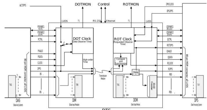
インターフェースの標準化
インターフェースの標準化
DPSCLOCK DPS1PPS ROT Clock (Requested Observe Time) DOT Clock(Data Observe Time)
QVALID QDATA RBS 0 RBS 31 Control DOM
(Data Output Module)
DTS
(Data Transmission System)
Figure 1: VSI-H Functional Block Diagram
VSI6.DRW ARW 21 Jun 2000 ALT1PPS
DPS
(Data Processing System)
Transmission Medium R1PPS RCLOCK 8 0 -p in M D R c o n n e c to r; a ll L V D S LVDS RS-232 PDATA BS0 BS31 1PPS CLOCK DIM
(Data Input Module)
DOTMON TVR TVG TV0 TV31 TVR TVG TV0 TV31 3 2 x 3 2 C ro s s b a r Notes:
1. Shaded items are for illustrative purposes only. 2. PVALID is optionally transmitted from DIM to DOM. 3. PDATA is optionally transmitted from DIM to DOM. 4. Data delay in DOM is required only for storage-based systems. 5. See text for discussion of use of optional use of P/QSPARE1/2 signals.
6. If DIM/DOM in single box, ALT1PPS/DPSCLOCK/DPS1PPS share single MDR-14 connector. 7. This diagram does not show all functions and options -- see VSI-H specification for details.
PVALID LVDS TTL Ethernet 8 0 -p in M D R c o n n e c to r; a ll L V D S DAS
(Data Acq System)
Compare and Synchronize High-order Time Delay ROT1PPS ROTMON QCTRL PCTRL PSPARE1 TTL (TVGCTRL) PSPARE2 (DOT1PPS) QSPARE1 (DPSCLOCKX) QSPARE2 (DPS1PPSX)
• VSI = VLBI Standard Interface
– VSI-H : Hardware = Aug. 2000
– VSI-S : Software (Commands + Control) = Feb. 2003 – VSI-E : Data Format
相関器
相関器
Mark4相関器(JIVE, オランダ) K4相関器(鹿島)
相関処理
時間→周波数 掛け算 XFタイプ 時系列 時系列 時間→周波数 時間→周波数 掛け算 時系列 時系列 FXタイプ相関器ブロック図
フリンジ回転 発生部 遅延追跡部 COS 相関積分部 SIN 相関積分部 位相校正信号 位相検出部 位相校正信号 位相検出部X
Y
SIN COS地球回転によって生じるドップ
ラーシフト
Xで受ける波 Yで受ける波 Oで受ける波 O X Yフリンジストッピングの定性的理
解
Xτ
&
> 0
0 0 f f fB 0 f + fB 0 0 f f f f 0 f + fB fB f B 0 f Y RF周波数帯 ビデオ周波数帯 フリンジ ストッピング 相互相関処理τ
g’三角関数の3レベル近似
アナログ 関数π
π
2
2
3
π
2
π
0
SIN COS +1 0 -1 +1 0 -1 SIN COS 3 レ ベル近似関数1ビット信号の相互相関
X
Y
Z(=X + Y)
排他的NORの真理値表
X Y Z
0 0 1
0 1 0
1 0 0
1 1 1
8ビットラグ相関器
シフトレジスタ カウンタ カウンタ カウンタ カウンタ カウンタ カウンタ カウンタ カウンタ X Y ラグ7 ラグ6 ラグ5 ラグ4 ラグ3 ラグ2 ラグ1 ラグ0宇宙測地技術の比較(
宇宙測地技術の比較(
VLBI, GPS,
VLBI, GPS,
SLR
SLR
)
)
VLBI GPS SLR グローバルな測位 ○ ○ ○ 時間分解能 ○ ◎ △ 長期安定性 ○ △ △ 天球基準座標系 ○ × × TOD (Time of Day) ○ ○ ○ 地球重心位置 × ○ ○ 極運動 ○ ○ ○ UT1-UTC ○ × × 天候の影響 小 小 大 大気遅延 有り(推定) 有り(推定) 有り(2色で補正) 電離層遅延 有り(2周波で補正) 有り(2周波で補正) 無し 衛星軌道誤差 無し ○ ○ 基準点 AZ/EL交点 アンテナ位相中心 AZ/EL交点基準座標系
基準座標系
Reference System と Reference Frame Reference System : 定義
Reference Frame : 定義の実現
ICRS
International Celestial Reference System
ITRS
International Terrestrial Reference System
ICRF92 ICRF [WGRF] ITRF97 ITRF2000 WGS84 測地成果2000 EOP/ERP
基準座標系と地球姿勢パラメタ
基準座標系と地球姿勢パラメタ
ICRF
International Celestial Reference Frame VLBI
EOP
Earth Orientation Parameters VLBI, (GPS), (SLR)
ITRF
地球姿勢パラメタ/地球回転パラ
地球姿勢パラメタ/地球回転パラ
メタ
メタ
Earth Orientation Parameter / Earth
Earth Orientation Parameter / Earth
Rotation Parameter
Rotation Parameter
極運動 UT1-UTC
極運動
極運動
(
(
Polar Motion / Wobble
Polar Motion / Wobble
)
)
0.1” = 3.09m
Chandler Wobble : 周期435日の変動 Annular Wobble : 1年周期の変動
UT1
UT1
-
-
UTC
UTC
と
と
LOD (Length Of
LOD (Length Of
Day)
Day)
UT1-TAI と UTC-TAI LOD LOD : GPS SLR VLBI で測定可 UT1-UTC : VLBI で測定可UT1
UT1
-
-
UTC
UTC
の決定に対する
の決定に対する
VLBI
VLBI
と
と
GPS
GPS
の寄与
の寄与
IERS Conventions
IERS Conventions
• IERS (International Earth Rotation
and Reference Systems Service)
が規定する標準的モデルや計算手
続きのドキュメント
– MERIT Standards : 1983
MERIT=Monitoring Earth Rotation and Intercomparison of Techniques
– IERS Standards : 1989, 1992 – IERS Conventions : 1996, 2003
• IAUやIAG(IUGG)の勧告や取り決
めに準拠
1秒の定義
1秒の定義
• 1956年まで
:1日の86400分の1
• 1956~1967年
:暦表時の1900年
1月0日12時に対する太陽年の
1/31556925.9747倍
• 1967年~
:セシウム133原子の基
底状態の2つの超微細準位間の
遷移に対応する放射の
9192631770周期の継続時間
時刻
時刻
TAI : International Atomic Time (国際原子時)
セシウム原子の振動数によって定義される時刻 BIPMで世界中の原子時計を荷重平均して計算
UTC : Coordinated Universal Time (協定世界時)
TAIにうるう秒を補正して得られる時刻 UTC = TAI-33sec (2006.1.1~)
GMT or JST-9
UT0 UT1 UT2 : 世界時 春分点の子午線通過を もとに定義される時刻
UT1
UT1
• UT0
観測地点における地方平均太陽時
を天体観測によって計測し、そこから観測
地点の経度の寄与のみ補正した平均太陽
時。観測地点の位置や季節により変動が
ある。
• UT1
UT0に極運動による影響の補正を
加えたもの。地球上の場所によらず一定。
• UT2
UT1から季節変動を取り除いたもの。
さらに詳細な時間の定義
さらに詳細な時間の定義
• TT : Terrestrial Time (力学時)
– TT = TAI+32.184sec
– TTの1秒は平均海面ポテンシャルにおける1秒で定義
• TDB : Barycentric Dynamical Time (太陽系力学時)
– 太陽系重心における時系で、TTから重力ポテンシャルと地球の公転運 動による相対論効果を補正したもので、TTを平均化したものになる – TDB = TT + 0.001658 sin( g ) + 0.000014 sin( 2g )
g = 357.53 + 0.9856003 ( JD - 2451545.0 ) deg
• TCB : Barycentric Coordinate Time (太陽系重心座標時)
– 太陽系重心における時系で、TTから重力ポテンシャルを補正したもの – d(TDB) / d(TCB) = 1-LB LB = 1.55051976772 × 10⁻⁸
• TCG : Geocentric Coordinate Time (地球重心座標時)
– 地球の重心における時系で、TTから重力ポテンシャルを補正したもの – d(TT) / d(TCG) = 1-LG LG = 6.969290134 × 10⁻¹⁰
ITRS
ITRS
(International Terrestrial Reference System)
(International Terrestrial Reference System)
• ITRS : 概念としての基準座標系
– 原点=地球の質量中心(海洋や大気を含む) – 時系は TCG (地球重心座標時)
– Z軸=BIH(Bureau International de l Heure:国際報時 局)が定義した極運動の epoch=1984.0 における CIO (Conventional International Origin:慣用国際原点)の 方向を初期値として、No Net Rotation プレート運動モデ ルにより時間発展
– X軸=BIHが定義した epoch=1984.0 における経度0°と 平均赤道面の交線の方向を初期値として、No Net
Rotation プレート運動モデルにより時間発展
– Y軸=X軸とZ軸から決まる方向(右手直交直線座標系) – Tide Free Potential 座標系を採用
潮汐(
潮汐(
Tides
Tides
)補正
)補正
太陽や月の重力がない仮 想的な状況における位置
ITRF
ITRF
(International Terrestrial Reference Frame)
(International Terrestrial Reference Frame)
• ITRF : ITRS を実現するため、個々の基準点の座標のリストを与えたもの
– BTS84⇒‥‥⇒BTS87⇒ITRF88⇒(89, 90, 91, 92, 93, 94, 96, 97)⇒ITRF2003 – 原点:SLRおよびGPSの解析結果を荷重平均
– スケール(長さ):VLBI, SLR, GPS の解析結果を荷重平均(TTで評価された解析結果を 約0.7ppb補正)
– No Net Rotation プレート運動モデルに NNR-NUVEL1モデルを採用
– コロケーションサイトにおける異なる観測技術間の地上測量(Local Tie)を用いて、VLBI, SLR, GPS, DORIS, PRARE, LLR の結果を統合
ICRS / ICRF
ICRS / ICRF
(International Celestial Reference System /
(International Celestial Reference System /
Frame)
Frame)
• ICRS : 概念としての基準座標系
– FK5 と整合性を保持
• FK5:光学カタログ(Fifth Fundamental Catalogue) • ± 50 mas – J2000.0 における春分点の方向で赤経原点を定義 – J2000.0 における平均赤道面で天の赤道を定義 • ICRF : ICRS を実現するため、個々の天体の座標のリストを与えたもの – ICRF88⇒‥‥⇒ICRF (1995) + Ext.1 (1999) – 毎年更新することをやめて、1995年のデータで固定 – 最新の章動モデル(IERS:1996)を用いた場合、J2000.0における平均極は 12h方向に17.1mas、18h方向に5.0masのずれ – 赤経の原点は、3C273Bの位置をFK5に拘束して計算 – 最新のLLR観測結果によると、赤経の原点は正しい春分点の方向から -55.4 ± 0.1 mas のずれ – Defining Source : 212 – 総天体数 : 667
IAU
IAU
歳差 章動モデルの
歳差 章動モデルの
VLBI
VLBI
による
による
改良
改良
旧
旧
IAU
IAU
モデル(
モデル(
Precession 1976 :
Precession 1976 :
Nutation
Nutation
1980
1980
)か
)か
らのオフセット
IAU
IAU
歳差・章動モデルの
歳差・章動モデルの
VLBI
VLBI
による
による
改良
改良
改良された
IVS
IVS
(国際VLBI事業)の位置付け
(国際VLBI事業)の位置付け
COSPAR
Committee on Space Research
IAG 国際測地学協会 IAU 国際天文学連合 IVS 国際VLBI事業 CSTG
Commission on International Coordination of Space Techniques for Geodesy and Geodynamics
ILRS 国際レー ザー測距事業
IGS
IVS
IVS
−組織
−組織
ー
ー
• • 情報情報通信通信研究機構研究機構 – – 観測局観測局 – – 相関局相関局 – – 解析センター解析センター – – データセンターデータセンター – – 技術開発センター技術開発センター • • 国土地理院国土地理院 – – 観測局観測局 – – 相関局相関局 • • 国立国立極地研究所極地研究所 – – 観測局(昭和基地)観測局(昭和基地) • • 国立天文台国立天文台 – – 観測局観測局 – – 相関局相関局 – – 解析センター解析センター国際VLBIプロジェクト
1970s 1980s 1990s
CDP
Crustal Dynamics Project
DOSE
Dynamics Of Solid Earth
IRIS/POLARIS
International Radio Interferometric Surveying POLar motion Analysis by Radio Interferometric Surveying
MERIT
(Monitoring of Earth Rotation and Intercomparison of the Techniques of Observation and Analysis)
1993
1988 1999
IGS 設立
IERS 設立 IVS 設立 IERS : International Earth Rotation and Reference System Service
IGS : International GNSS Service
国際協力
国際協力
•• CDP : CDP : Crustal Dynamics Project (1980~)Crustal Dynamics Project (1980~)
–
– VLBI VLBI およびおよび SLR SLR によるプレート運動測定によるプレート運動測定
•
• IRIS : IRIS : International Radio Interferometric Survey (1984~)International Radio Interferometric Survey (1984~)
–
– 地球回転パラメタの測定のためのVLBI観測(地球回転パラメタの測定のためのVLBI観測(IRISIRIS--A, IRISA, IRIS--P, P, ……))
•
• DOSE : DOSE : Dynamics of Solid Earth (1990~)Dynamics of Solid Earth (1990~) •
• CORE : CORE : Continuous Observation of Earth Rotation (2000~)Continuous Observation of Earth Rotation (2000~) •
• IERS : IERS : International Earth Rotation Service (1988~)International Earth Rotation Service (1988~)
–
– 国際地球回転事業国際地球回転事業
•
• IVS : IVS : International VLBI Service for Geodesy and Astrometry (2000~)International VLBI Service for Geodesy and Astrometry (2000~)
–
VLBI2010 : IVS
VLBI2010 : IVS
の将来計画
の将来計画
• e-VLBI のルーチン化
– 処理時間の短縮 – 高頻度自動観測・自動処理• 小型単一設計アンテナの採用
– 重力変形の影響極小化 – 高感度化• 最適なアンテナ配置
• RFI(不要電波干渉)対策
• 高精度化
– 遅延時間∼3psec – 位置決定精度∼1mmVLBI2010 :
VLBI2010 :
アンテナ
アンテナ
• Design a new observing system based on small antennas
– automated and unattended operation
– small antennas (10-12 m diameter) that are fast-moving and mechanically reliable
– economic replication of antennas
– broad, continuous observing frequency range (1-14 GHz)
• includes current S-band and X-band frequencies for backwards compatibility
• allows much more agility to avoid RFI
• allows more bandwidth to significantly improve delay measurement precision
– update the best of the existing large antennas with the new small-antenna system for compatibility
• allows co-observations to preserve continuity with the historical record • allows improvement of the CRF measurements made primarily by the
VLBI2010 :
VLBI2010 :
検討されている
検討されている
12m
12m
アンテナ
VLBI2010 :
VLBI2010 :
データ処理
データ処理
• Transfer data with a combination of high-speed
networks and high data-rate disk systems
– Data recording rates and transmission rates are rapidly increasing
• Examine the possibilities for new correlator
systems
– handling the anticipated higher data rates
– using commodity PC platforms, possibly widely distributed.
• Automate and streamline the complete
data-analysis pipeline
– enabling rapid turnaround
VLBI2010 :
VLBI2010 :
今後の検討
今後の検討
• System studies and simulations:
– error budget development
– decisions on observing frequencies – optimal distribution of new sites – number of antennas per site
– new observing strategies – transition plan.
• Development projects and prototyping:
– small antenna system – feed and receiver – cost and schedule
– higher data rate system – correlator development – backend development
VLBIを用いた研究
分野
VLBIによる研究分野
VLBIによる研究分野
• 精密測位
– 地殻変動、プレート運動、基準座標系の構築• 地球回転計測
– 極運動・自転 (UT1-UTC, TOD)・章動、地球内部構造• 位置天文
– 基準座標系の構築、天体までの測距• 天体のイメージング
プレートテクトニクス理論の検証
プレートテクトニクス理論の検証
鹿島 ハワイ アラスカ 5700km 5700km 5400km 5400km 4700km 4700km 日米VLBI実験 日米VLBI実験 (1984∼) (1984∼) プレート運動の実測 プレート運動の実測VLBI計測によって得られたプレート
運動
基線長変化の実測値
基線長変化の実測値
鹿島−ハワイの基線長変化 -400 -200 0 200 400 1984 1986 1988 1990 1992 1994 年 基線長 ( m m ) アラスカ−ハワイの基線長変化 -400 -200 0 200 400 1984 1986 1988 1990 1992 1994 年 基 線長( m m ) 鹿島−アラスカの基線長変化 -400 -200 0 200 400 1984 1986 1988 1990 1992 1994 年 基 線長( m m ) 変化率 −63.5±0.5mm/年 変化率 1.3±0.5mm/年 変化率 −46.1±0.3mm/年西太平洋電波干渉計
西太平洋電波干渉計
34m
10m 3m
南鳥島の動き
南鳥島の動き
3cm 1年間の動きの 予測値 北 東 1991年 1989年 1990年首都圏広域地殻変動観測システム
KSP = Key Stone Project
VLBI(超長基線電波干渉):11mアンテナ SLR(衛星レーザー測距):75cm望遠鏡 GPS(汎地球測位システム):測地受信機
KSP観測網:4局6基線(1994∼200
1)
KSP−VLBI網(非常にコンパク
KSP−VLBI網(非常にコンパク
ト)
ト)
小金井 三浦 館山 100km 鹿島3つの宇宙測地技術のコロケーション
VLBI
SLR GPS
首都圏広域地殻変動観測計画
首都圏広域地殻変動観測計画
要石計画 要石計画 K Key ey S Stone tone P ProjectrojectKey Stone Project (VLBI) の特徴
• リアルタイムVLBIの実現
– リアルタイムデータ伝送システム+リアルタイム相関器の開発• 完全自動化システム
– 観測の自動化 無人運用システム – データ処理・解析の自動化 – 迅速な処理と解析結果の自動公開 – 高頻度連続観測• 小口径・高感度VLBI観測
– 56Mbps 256Mbps• 3つの宇宙測地技術のコロケーション
– 座標系の結合・構築KSP−VLBIシステム
KSP−VLBIシステム
•
•
アンテナ直径
アンテナ直径
:
:
11 m
11 m
•
•
観測局数
観測局数
:
:
4
4
•
•
データレート
データレート
:
:
256 Mbps (16 Mbps x 16
256 Mbps (16 Mbps x 16
ch
ch
)
)
–– XX--band: 10 band: 10 chch, S, S--band: 6 band: 6 chch
•
•
データ収集ターミナル
データ収集ターミナル
:
:
KSP (K4)
KSP (K4)
•
•
1セッション(実験)長
1セッション(実験)長
:
:
24
24
時間
時間
(隔日)
(隔日)
•
•
運用モード
運用モード
:
:
– – 実時間VLBI実時間VLBI 及び及び テープベースVLBIテープベースVLBI•
•
定常運用期間
定常運用期間
:
:
2001年度まで
2001年度まで
KSP鹿嶋局
昔ながらのVLBI観測と処理
昔ながらのVLBI観測と処理
相関処理
実時間VLBI
実時間VLBI
相関処理
相関処理
高速ネットワーク 高速ネットワークリアルタイム
VLBIの実現
• 2.4 Gbps 高速光通信ATMネットワーク • 新開発データ送受信装置
完全自動化システム
01:15 UT 23:45 UT 観測 テープ 集荷 テープ 到着 テープ セット 翌朝 相関処理 解析 テープベースVLBI観測(ほぼ自動化+ほぼ無人観測) データ 公開 01:15 UT 00:45 UT 観測+相関処理 解析 リアルタイムVLBI観測(完全自動化+完全無人観測) データ 公開測位精度の向上
鹿島−小金井基線 1997.9.30 24時間観測開始 1997.6.4 256Mbps + リアルタイム VLBI 1995.12.1 三浦局運用開始 1996.5.14 56Mbps から64Mbpsへ 1996.9.3 館山局運用開始測位精度の向上
基線長
再現性
24時間 観測開始 3局3基線 観測開始 受信機室 エアコン の改善内部誤差
局位置推定値の再現性(mm) 1997.9.30-1998.11.14 東西 南北 鉛直 小金井 2.2 2.0 10.7 三浦 2.3 2.5 12.1 館山 2.5 2.4 11.1