EVALUATION OF SILICONE POTTING COMPOUND AND SILICONE ADHESIVE EXPOSED TO SPACE ON SM/SEED EXPERIMENT
Eiji MIYAZAKI, Kazuyuki MORI, Junichiro ISHIZAWA and Hiroyuki SHIMAMURA Institute of Aerospace Technology, Japan Aerospace Exploration Agency,
Tsukuba,Ibaraki 305-8505, Japan
JAXA has developed a silicone potting compound and adhesive. The samples were exposed to space on SM/SEED outside the ISS to evaluate their tolerance against a space environment. The developed silicone materials are fundamentally designed for interior use: exposed environments are not considered. This experiment was performed to evaluate whether the silicone materials have tolerance against space environments outside the ISS or not. The samples are two parts silicone potting compound and one part silicone adhesive, manufactured by Shin-Etsu Chemical Co. Ltd. Results show that the potting compound sample, the electrical properties, relative permittivity H, and dielectric tangent tanG meet the requirements.
Cross-sectional TEM revealed that the new layer, found as SiO2, is built on the surface. The layer can be formed by atomic oxygen collision with silicone that is contained in the potting compound and contamination. For the adhesive, the fracture strength evaluated using a tensile lap-share test is 1.1–1.6 MPa, meeting the requirement that it be more than 1.0 MPa. The experiment verified that the silicone potting compound and adhesive can retain their performance for exposure to space on ISS orbit for up to 46 months.
Keywords: silicone, relative permittivity, dielectric tangent, tensile lap-share test
1. Introduction
To evaluate the tolerance of a silicone potting compound and adhesive developed by JAXA under a space environment, specimens of the developed silicone potting compound and adhesive were exposed to space outside ISS as SM/SEED samples. The silicone materials are fundamentally designed for inside use: exposed environments were not considered. For promotion of applications of the developed materials to outside use, this experiment was performed. The purpose was to evaluate whether the materials have tolerance against a space environment outside ISS or not by the SM/SEED mission.
This reportpresents test results for the silicone potting compound and the adhesive in separate sections because the samples have different properties to be evaluated: results for the silicone potting compound are described in section 2; those for the silicone adhesive are described in section 3.
2. Silicone potting compound 2.1 Experimental
The sample is two-part silicone potting compound
“KE-101A/B” manufactured by Shin-Etsu Chemical Co., Ltd.
The general properties of KE-101A/B are shown in Table 1.
The potting compound was applied 3-mm-thick onto aluminum substrates of 20 mm × 20 mm × 1 mmt as an SM/SEED sample.
The samples are set in holes made in the SM/MPAC&SEED hardware, held by holding plates with a 16 mm × 16 mm window: the area within the window is the actual exposed area.
The retrieved samples were evaluated as follows:
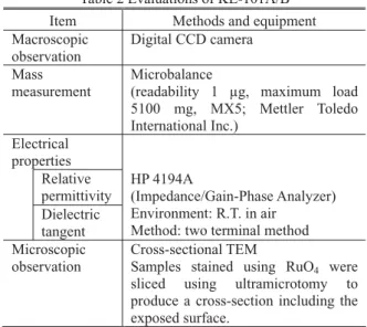
macroscopic observation, mass, electrical properties (relative permittivity H and dielectric tangent tanG), and cross-sectional microscopic observation near surface. Evaluation items and methods are presented in Table 2.
Table 1 General properties of KE-101A/B
KE-101A/B
Appearance Clear and colorless
Hardness (Durometer A) 40 Breakdown voltage 1 mm 27 kV
1 Hz 2.5 1 MHz 2.9 Relative permittivity
10 MHz 3.5 1 Hz 0.0010 1 MHz 0.0007 Dielectric tangent
10 MHz 0.0010 TML*1 0.357 % Outgassing
(ASTM-E595[1]) CVCM*1 0.057 %
Curing conditions: 23±2°C, 50±5%RH, 168 h (JIS K 6249)
*1) TML: Total Mass Loss, CVCM: Collected Volatile Condensable Materials
Table 2 Evaluations of KE-101A/B
Item Methods and equipment
Macroscopic observation
Digital CCD camera Mass
measurement
Microbalance
(readability 1 μg, maximum load 5100 mg, MX5; Mettler Toledo International Inc.)
Electrical properties
Relative permittivity Dielectric tangent
HP 4194A
(Impedance/Gain-Phase Analyzer) Environment: R.T. in air
Method: two terminal method Microscopic
observation
Cross-sectional TEM
Samples stained using RuO4 were sliced using ultramicrotomy to produce a cross-section including the exposed surface.
2.2 Results and discussion 2.2.1 Macroscopic observation
Figure 1 presents images of macroscopic observations.
The difference of brightness between samples resulted from lighting while taking photographs. The difference is unrelated to a color change of the sample surface: a flat surface of the substrates beneath the potting compound is reflecting. The photographs show no marked change in potting compound, although a slight trace of the frame attached on the sample surface is visible on some samples: #1-A and #2-B.
2.2.2 Mass measurement
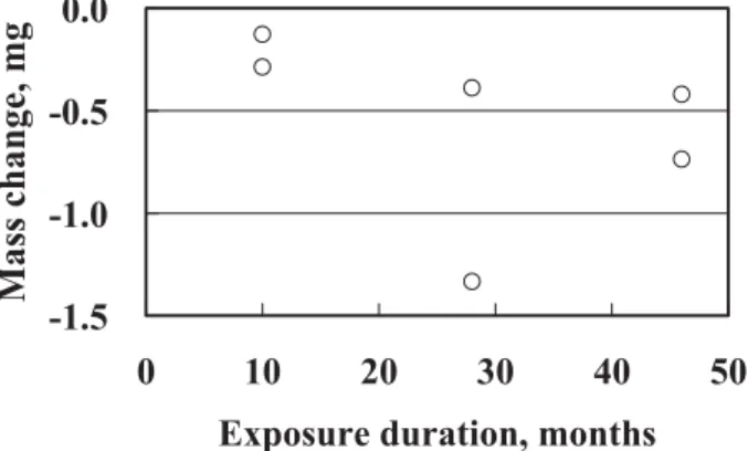
The mass changes of exposed samples are presented in Fig.
2, indicating that the mass decreases more as the exposure duration lengthens. The maximum mass loss was 1.3 mg for
#2-A with initial mass of ca. 0.8 g, excluding the substrate. It is greater than that for #3. Outgassing might be one cause of such mass loss in TML: 0.396% of 0.8 g, or ca. 3 mg. The temperature is lower than the outgassing test condition. The level is reasonable. Some influential factor such as heating might occur.
For comparison, the mass loss of AO monitoring sample, VESPEL, is much greater than that of the potting compound[2]: 2.4 mg for VESPEL mounted on #1 exposed for 10 months. It is about 10 times greater than that of the potting compound.
2.2.3 Electric properties
Results of relative permittivity and the dielectric tangent are presented respectively in Figs. 3 and 4. The relative permittivity showed no significant change. It met the requirement of being less than 3.8. The dielectric tangent, however, showed a slight increase from the initial value. It can be said to be maintained within the requirement: less than 0.003.
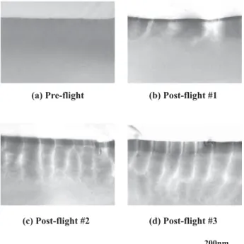
2.2.4 Microscopic observation
Figure 5 presents cross-sectional TEM images of the sample surface. The vertical lines found in the retrieved samples are not related to the sample shape, but are made at making a specimen for TEM observation. The images revealed that a new layer was built up on the surface that was not found on the surface of the as-received sample. The layer thicknesses are: ca. 30 nm for #1, ca. 80 nm for #2, and ca. 150 nm for #3.
Thicknesses of the new layers are comparable to the thickness observed for F-OSR[3]. Results show that the layer was SiO2. The layer can be formed by atomic oxygen collision with silicon contained in the potting compound and/or contamination deposited on orbit. Such a phenomenon is already known for silicone materials used on LEO spacecraft[4,5].
2.2.5 Discussion
As presented in Fig. 2, a mass loss occurred. For the silicone potting compound, a mass change, either a gain or loss, is attributable to outgassing, erosion by AO, or deposition of contamination. In terms of outgassing, its TML is 0.357%. The initial mass is 790 mg, i.e., the mass loss by outgassing can be expected up to 2.8 mg. According to ASTM-E595, the TML is measured by exposure in vacuum at 125°C for 24 h [1].
Unfortunately, the experimental condition of SM/SEED differs from the outgassing test condition, i.e., longer exposure at
Fig. 2 Results of mass change of retrieved potting compound from SM/MPAC&SEED exposure.
-1.5 -1.0 -0.5 0.0
0 10 20 30 40 50
Exposure duration, months
Mass change, mg
㪈㪇㫄㫄㩷 Fig. 1 Macroscopic images of Potting compound
(a) Pre-flight
(b) #1-A (left) and #1-B (right)
(c) #2-A (left) and #2-B (right)
(d) #3-A (left) and #3-B (right)
lower temperature. For that reason, it cannot be said that the actual mass loss was caused by outgassing for the retrieved sample. The second factor of mass change, erosion by AO, can contribute to mass loss initially at the time of exposure. As depicted in Fig. 5, the AO protective SiO2 layer was built up on the exposed surface. Once the layer is organized, the AO erosion is blocked: mass loss stops. The AO protective layer of ca. 10 nm is sufficiently thick[6]; it is organized before #1 retrieval because the layer’s thickness of the #1 sample was ca.
30 nm. Therefore, the mass loss caused by AO erosion can occur only at the beginning of exposure. The third factor, deposition of contamination, also contributes to the mass change. Based on the result of F-OSR, a mass gain of up to 0.07 mg is expected, assuming that the same deposition occurred as F-OSR. It is sufficiently smaller than the total mass change of the potting compound sample. Therefore, it can be concluded that the mass loss is mainly caused by outgassing.
Electric properties are not affected by space environment exposure. It can be concluded that the tolerance of the potting compound is verified by the SM/MPAC&SEED experiment.
2.3 Conclusion
Results of this experiment verify that the JAXA-developed silicone potting compound can retain its properties within the requirement for 46 months’ exposure on ISS. A new layer of SiO2 was observed on the retrieved sample surface, which is similar to other silicone materials collided with AO. Results of this investigation show that the mass loss is mainly the result of outgassing.
3. Silicone adhesive 3.1 Experimental
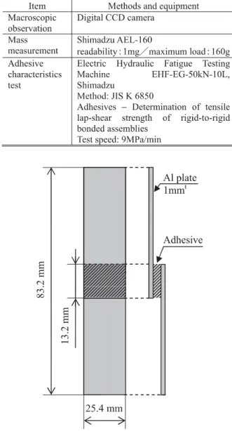
The sample is one part silicone adhesive (KE4908SC-T;
Shin-Etsu Chemical Co. Ltd.). General properties of KE4908SC-T are portrayed in Table 3. The adhesive of 13.2 mmL × 25.4 mmW × 2 mmt is cured between two 83.2 mm × 25.4 mm × 1 mmt aluminum plates before flight, as depicted in Fig. 6. The specimen was tested for adhesive properties according to the standard test specification (JIS K 6850 – Adhesive – Determination of tensile lap-shear strength of rigid-to-rigid bonded assembly).[7] A schematic illustration of the installation to SM/MPAC&SEED hardware and the exposed area is portrayed in Fig. 7.
The retrieved samples are evaluated using macroscopic observation, mass measurement and adhesive characteristics test. The evaluation items and methods are presented in Table 4.
Table 3 General properties of KE4908SC-T
KE4908SC-T
Appearance Semi transparent
Hardness (Durometer A) 46 Lap share strength 1.7 MPa Breakdown voltage 1 mm 26 kV Relative permittivity 50 Hz 3.0 Dielectric tangent 50 Hz 0.0012
TML*1 0.396 % Outgassing
(ASTM-E595) CVCM*1 0.008 %
Curing conditions: 23±2°C, 50±5%RH, 168 h (JIS K 6249)
*1)TML: Total Mass Loss, CVCM: Collected Volatile Condensable Materials
Fig. 5 Cross-sectional TEM images of potting compound for SM/MPAC&SEED (a) Pre-flight (b) Post-flight #1
(c) Post-flight #2 (d) Post-flight #3 200nm Fig. 4 Results of measured dielectric tangent of retrieved potting compound from SM/MPAC&SEED
0.000 0.001 0.002 0.003 0.004
0 10 20 30 40 50
Exposure duration, months Dielectric tangent @ 1 MHz, R.T.
Fig. 3 Results of measured relative permittivity of retrieved potting compound from SM/MPAC&SEED
0.0 1.0 2.0 3.0 4.0
0 10 20 30 40 50
Exposure duration, months Relative permittivity @ 1 MHz, R.T.
3.2 Results
3.2.1 Macroscopic observation
Figure 8 portrays the surface appearance, including the exposure area. The adhesive sample is not visible in the figure:
the sample is hidden by the upper substrate.
From the figure, semi-circular stains can be found near the adhesive sample on the lower substrate for retrieved samples.
Apparently, some liquid oozed from the adhesive sample. The stain is very thin. In addition to the stains, color changed areas are visible for #2 and #3 retrieved samples along the shape of the exposure window.
3.2.2 Mass measurement
Figure 9 presents measured results of the differences in mass between pre-flight and post-flight conditions. The mass changes of exposed samples show complicated data: decreased samples are #1-B, -0.002 g and #2-B, -0.011 g; increased samples are #1-A, +0.014 g, #2-A, +0.003 g, #3-A, +0.014 g, and #3-B, +0.005 g.
3.2.3 Adhesive characteristics test
Figure 10 depicts the relationship between the crosshead displacement and the load obtained as ascertained through tensile lap-shear tests. The sample was fractured at the peak of each curve: the curve shown at the more displaced region beyond the fracture displacement is unrelated to actual test results. The pre-flight and post-flight slopes differ in shape. The pre-flight slope is not linear; the post-flight slopes are linear.
The fracture lap shear strength and crosshead displacement are presented in Table 5. The lap shear fracture strength is 1.1–1.6 MPa. The values met the requirement of being greater than 1.0 MPa. No requirement value is set for the crosshead displacement. Therefore, it cannot be discussed in terms of meeting the requirement or not. The value of the crosshead displacement itself for retrieved samples is obviously lower than that of the pre-flight sample.
3.2.4 Discussion
The cured adhesive does not ooze any liquid, although outgassing can occur. If the stain had resulted from outgassing, the stain shape would not be natural, i.e., the shape must have full width along the sample and the edge of the far side from the sample must be unclear. Therefore, we infer that the stain might result from the residual sample. The protruded sample would be wiped out during manufacturing. A trace of it might be developed visually through exposure to the space environment.
The mass change data are confusing. The total mass of each specimen, i.e., the adhesive sample and two aluminum substrates, is ca. 13 g. The balance used for this study has 0.001 g readability. With a maximum change of 14 units of readability, it is difficult to determine the significance of the mass change.
The lap shear test result shows the change of ductility of the adhesive sample. The pre-flight sample can be said to have ductility from its nonlinear behavior at loading. All retrieved samples indicate linear behavior, i.e., elastic deformation is dominant. That result might be attributable to exposure to the space environment. Although such ductility is lost, the experiment verified that the required basic properties can be retained, even in the exposed environment on the ISS.
3.3 Conclusion
Silicone adhesive (KE4908SC-T) was exposed for the 46 month-SM/SEED experiment. Degradation in elongation and loss of ductility were found, although the required properties are verified to be retained for up to 46 months’ exposure on the ISS.
References
[1] ASTM E595, “Standard Test Method for Total Mass Loss and Collected Volatile Condensable Materials from Outgassing in a Vacuum Environment,” ASTM International.
[2] Yugo Kimoto, Keiichi Yano, Junichiro Ishizawa, Eiji Miyazaki, and Ichiro Yamagata, “Passive Measurement of Atomic Oxygen, UV Fluence, and Radiation Effect on the ISS Using the SEED experiment” , Proc. 10th ISMSE, ESA-SP-616 (2006).
[3] Eiji Miyazaki and Ichiro Yamagata, “Results of Space-Environment Exposure of the Flexible Optical Solar Reflector,” Journal of Spacecraft and Rockets, in press (2008)
[4] United States Patent 5073607
[5] R. I. Gonzalez, S. J. Tomezak, T. K. Minton, A. L.
Brunsvold, and G. B. Hoflund, “Synthesis and Atomic Oxygen Erosion Testing of Space-Survivable POSS (Polyhedral Oligomeric Silsesquioxane) Polyimides,”
Proceedings of the 9th International Symposium on
“Materials in a Space Environment”, ESA-SP-540, European Space Agency, pp. 113-120 (2003)
[6] M. Tagawa, K. Yokota, N. Ohmae, and H. Kinoshita,
“Volume diffusion of atomic oxygen in D-SiO2 protective coating,” High Performance Polymers, Vol. 12, pp. 53-63 (2000).
[7] JIS K 6850, “Adhesives㧙Determination of tensile lap-shear strength of rigid-to-rigid bonded assemblies,”
Japanese Industrial Standards
Publication list related SM/MPAC&SEED
E. Miyazaki, and K. Mori, “Evaluation of Potting Compound Exposed to Space Environment on ISS Russian Service Module / Space Environment Exposure Device,” Proceedings of UKAREN 51, 200