Experimental and numerical study of premixed
flame penetration and propagation in
multichannel system
著者
Roman Fursenko, Evgeniy Sereshchenko, Georgii
Uriupin, Egor Odintsov, Takuya Tezuka, Sergey
Minaev, Kaoru Maruta
journal or
publication title
Combustion Science and Technology
volume
190
number
6
page range
1023-1040
year
2018-02-26
URL
http://hdl.handle.net/10097/00126943
doi: 10.1080/00102202.2018.1424143Experimental and numerical study of premixed
flame penetration and propagation in multi-channel
system
Roman Fursenko
1,2, Evgeniy Sereshchenko
1,2, Georgii Uriupin
2,
Egor Odintsov
1,2, Takuya Tezuka
3, Sergey Minaev
2, and Kaoru Maruta
2,31
Institute of Theoretical and Applied Mechanics SB RAS, Novosibirsk,
Russia
2
Far Eastern Federal University, Vladivostok, Russia
3Tohoku University, Sendai, Japan
January 2, 2018
Abstract
Experimental and numerical results on premixed flame penetration and subse-quent propagation in a multi-channel burner are presented. The burner consists of the set of planar straight quartz channels which transverse sizes can be varied. It is found, that depending on mixture flow rate, equivalence ratio and channels transverse sizes a big variety of combustion regimes can be observed. These regimes include burner stabilized flames, upstream propagating flames and flames stabilized under the burner external surface. The placement of different combustion regimes in equivalence ra-tio / flow rate plane is plotted by means of experimental and numerical studies. In wide range of parameters, the flame pulsations consisting of repetitive stages of flame ignition, upstream propagation and quenching take place. Results of numerical sim-ulations obtained in the framework of simplified thermal-diffusion model are found to be in a good qualitative agreement with experimental data and allow to explain experimental findings.
1
Introduction
Effective heat recirculation is distinctive feature of combustion processes in porous media and meso-scale channels. Heat feed-back from the high temperature combustion prod-ucts by radiation and conduction through solid medium results in higher burning veloc-ities (Min and Shin, 1991), superadiabatic temperature in the reaction zone (Babkin and Laevskii, 1987; Kotani and Takeno, 1982), extension of the flammability limits (Aldushin, 1993; Min and Shin, 1991), low emission of pollutants (Khanna et al., 1994; Liu and Hsieh, 2004), high radiant output (Sathe et al., 1990) and the ability to burn fuels with a low energy content. These features have found practical use in a number of applications (Abdul Mujeebu et al., 2009) which in turn stimulated further fundamental investigations of filtrational gas combustion in inert porous media and micro-channel systems (Howell et al., 1996).
Most experimental and numerical studies are devoted to flame propagation and stabi-lization in an interior of porous media. Babkin and Laevskii (1987) studied flame propa-gation in inert porous media both theoretically and experimentally and obtained U-shape dependency of flame propagation velocity on gas filtration velocity. It was found that flame propagates with the velocities amounting to the fractions of millimeters per second. For the flame propagating in a narrow tube with heat conducting wall, the same value of typ-ical flame spread velocity was experimentally and theorettyp-ically obtained (Zamashchikov, 2001; Zamashchikov and Minaev, 2001). Since typically the flame propagation velocity is equal to zero for only one value of mixture flow rate, stationary flames in homogeneous porous media with uniform filtration were observed only in micro-fibrous porous media with unique properties (Yang et al., 2009; Fursenko et al., 2010; Liu et al., 2015). There-fore, for flame stabilization inside the porous media non-homogeneity of different kinds are used. The flame can be stabilized at an interface between two medias with different porosity or pore size (Hsu et al., 1993; Smucker and Ellzey, 2004; Hashemi and Hashemi, 2017), near the face of the porous layer (Min and Shin, 1991; Kotani and Takeno, 1982; Li et al., 2016), in a thermally non-homogeneous porous media (Mohamad et al., 1994) or in a non-uniform mixture flow (Kakutkina and Babkin, 1998; Zhdanok et al., 1998; Yilmaz et al., 2017). Sathe and colleagues (1990) have experimentally investigated flame stabilization in a porous layer of 5.1 cm long and found that stable combustion could be maintained in two spatial domains, one in the upstream half of the layer and another at the downstream edge of the porous segment. Min and Shin (1991) performed experimental investigations of flame stabilization in uninsulated 2 cm length honeycomb combustor. On the basis of soot lines observed in the cross-section of the combustor they singled out two different stationary combustion modes. The first one is represented by almost planar flame stabilized in the upstream part of the honeycomb burner. In the second regime the flame is
curved in shape, with the flame at the downstream end near the burner edge and fairly flat in the upstream half near the burner center. Numerical simulations of flame stabilization in a set of finite length parallel plate channels (Hackert et al., 1999) also demonstrated the possibility of macroscopic curvature of the flame related with transverse heat losses. However, clarification of the mechanism of submerged flame stabilization demands further fundamental investigations.
In some experiments the sound emission or hissing noise from the porous or mi-crochannel burners was detected (Janvekar et al., 2017; Terracciano et al., 2017; Lee and Noh, 2016). Such noise may arise due to combustion instability. In (Sirotkin et al., 2017) the possibility of appearance of pulsating regions on the flame front was numerically demonstrated. These pulsations were shown to have the same nature as flame repetitive ignition and extinction regime (FREI) which accompanied with noise and was observed in experiments on combustion in externally heated narrow tube (Maruta et al., 2005). How-ever, such non-stationary flame behavior can not be experimentally studied in details due to the opacity of most materials that prevents any visual and intrusive measurements. Ran-dom and irregular structure of porous materials makes it difficult to identify the main reg-ularities determining the dynamic flame behavior on the pore scales. Thus, many aspects concerning flame dynamics in the course of combustion wave penetration in porous media as well as flame stabilization in the vicinity of porous media / open space interface were not considered in details. At the same time, these problems are relevant to flame arrestors, porous radiant burners and to further development of combustion fundamentals.
Some similarities between filtrational gas combustion and flame propagating in the nar-row channels (Zamashchikov and Minaev, 2001) suggest that investigations of idealized system consisting of the set of microchannels may provide relevant knowledge on flame dynamics inside the porous media and near its interface. Notice that the same approach to experimental investigations of filtrational combustion waves was previously applied in (Lee and Noh, 2016) where a disk-shaped part of the cylindrical porous media was mod-eled as a radial multi-channel made of thin quartz plates. In multi-channel systems, it is possible to exclude probabilistic factors associated with porous media irregularity and investigate the mere effects of heat and mass transfer on flame behavior. This problem is also of independent interest due to the recent tendencies to the development of energy conversion systems (Su et al., 2016), flame arresters and heaters based on microchannels or regularly structured media. Lamella burner (JUNKERS, 1998; Lucio and Fernandes, 2016) provides an example of practical application of multi-channel type burner in boilers for central heating systems. Results of numerical simulations of combustion in lamella burner and some experimental data were presented in (Parmentier et al., 2003). In numer-ical model isothermal channel walls were assumed and steady state solutions describing flames stabilized at channels outlet were studied. The problems of flame penetration into
the burner were beyond the scope of these studies.
In the present study we examine the combustion processes in a system consists of the set of planar quartz ducts shown in Fig. 1. Such configuration allow us to observe flame dynamics and control spatial distribution of channels sizes by variation of the gaps between the quartz plates forming ducts. The presence of differently sized channels can be regarded as a model of pore size non-uniformity typical for porous media. The length of the system in flow direction is 12 cm, so that both flame penetration in the channels and dynamics of the subsequent flame propagation inside the multi-channel combustor can be studied. It should be noted that the system of such length can be treated as the model of semi-infinite porous media rather than finite size burners studied in (Min and Shin, 1991; Sathe et al., 1990). The main purpose of the present study is to detect characteristic features of flame penetration and propagation in the multi-channel burner, as well as clarification of the mechanism of flame stabilization under the burner interface. Unlike existing works on combustion in porous media and microchannel systems, the results of visual observations of flame dynamics in specially developed transparent multi-channel system are presented for the first time. Besides experimental data, the results of two-dimensional numerical simulations in the frame of thermal-diffusion model are presented and compared with experiments.
2
Experimental setup
Assembly model and photograph of the multi-channel burner are shown in Fig. 1 a and b. The quartz plates of 6 cm width, 12 cm height and 0.1 cm thickness are held by the bottom and upper holders with grooves form the parallel channels walls. The distance between the centers of two neighboring grooves is 0.2 cm. Thus, the channels inner transverse size can be step-wisely varied from 0.1 cm to 5.1 cm with 0.2 cm step. The total number of channels in the system can range from 1 to 20. This number depends on channels transverse size and on the number of available quartz plates. Methane-air mixture is supplied into the channels through the rectangular slot which size is varied by installing the appropriate flange so that to fit the total size of the multi-channel system. Three-layer fine steel mesh clamped between the flanges overlaps the inlet slot in order to provide near flat flow velocity profile. Methane and dry air were used as fuel and oxidant. Methane and air flow rates were controlled by flow controllers Kofloc3200 with operating range 1 SCCM - 20 SLM and Yamatake MQV0050 (operating range 0.4-50 SLM), correspondingly. The accuracy of the measured mass flow rates at 20◦C was not higher than ±1% of full scale. Flow controllers were controlled by PC through AD/DA converter. Fuel and oxidant were fully premixed in a static mixer before being supplied to the multi-channel system. The mixture was ignited
Fig. 1. Photograph (a), assembly model (b) and schemes of examined configurations of the multi-channel burner (c).
in free space in the vicinity of the channels outlet by pilot flame which was removed immediately after flame initiation above all channels. The flame behavior was recorded with two digital cameras (Nikon D800) which were mounted perpendicular and parallel to the quartz plates forming the channels. Photographing with 7360 × 4912 resolution were conducting in manual mode with an exposure time 0.5 s without flash. In the course of each experiment mixture flow rate and equivalence ratio were remained unchanged. Between consecutive experiments the burner was cooled to the room temperature.
Experiments were conducted for equivalence ratios 0.7 ≤ φ ≤ 1.3, flow rates Q ≤ 700 cm3/s and three different configurations of the multi-channel burner differing in inner size of the channels. The first and second configurations consist of seven equally sized channels of transverse dimension 0.3 and 0.1 cm respectively. Below, these configurations will be referred as I and II. In the third configuration which will be denoted as III, the channels of inner size 0.1 and 0.3 cm alternate. Herewith, the transverse size of edge channels is 0.3 cm and the total number of channels is 7. Schematic representations of the examined configurations are shown in Fig. 1c. Notice that for stoichiometric methane-air
mixture quenching distance is about 0.22 cm and it increases with the shift of equivalence ratio to the lean or rich regions and is about 0.3 cm for φ = 0.8 and φ = 1.2 (Harris et al., 1948).
3
Mathematical model
Numerical study of lean premixed flames penetration in the multi-channel system was performed in the framework of two-dimensional thermal-diffusion model with prescribed time-independent velocity flow field. This model assumes constant thermal properties, constant density, and one-step irreversible chemical reaction. In appropriately chosen units the set of dimensionless equations for gas temperature (T ), temperature of the walls (Θ) and fuel concentration (C) can be written in the following form:
∂T /∂t + (V∇)T = ∆T + (1 − σ)W − hrg(T4− σ4) (1)
∂Θ/∂t = κ∆Θ (2)
∂C/∂t + (V∇)C = Le−1∆C − W (3) Non-dimensional velocity vector V = (Vx, Vy) in equations (1)-(3) is measured in units
of laminar burning velocity in large activation energy limit Ub and assumed to be given.
This vector is pre-calculated from the steady state incompressible Navier-Stokes equations for the non-reactive mixture in given channels configuration. Gas and wall temperatures in equations (1)-(3) are measured in units of Tb, the adiabatic temperature of combustion
products, fuel concentration C is expressed in units of C0, its value in the fresh mixture.
The Cartesian coordinates x, y are used and distance is measured in units of flame thermal thickness lth = Dth/Ub, where Dth is the mixture thermal diffusivity. Non-dimensional
time t is measured in units of tth = Dth/Ub2. Non-dimensional ambient temperature σ is
defined as σ = T0/Tb where T0 = 300 K is the dimensional initial temperature, Le is the
Lewis number, κ = Ds/Dth, where Ds is the thermal diffusivity of the channels walls,
W = ((1 − σ)N )2/(2Le)C exp(N (1 − 1/T )) is the chemical reaction rate, N = Ta/Tbis
the scaled activation energy, Ta is the activation temperature. Non-dimensional radiative
heat loss intensity hrgdepends on the composition of fresh mixture as hrg = A(1−σ)/σeN
(Buckmaster, 1997; Minaev et al., 2003), where coefficient A = 4.66 · 10−6 was chosen so that the numerical simulations of freely propagating premixed flame give the value of lean flammability limit equal to 0.5 that is close to the experimentally determined value for methane/air mixture (Coward and Jones, 1952).
Computational domain is shown in Fig. 2. It consists of two channels of length L1
which transverse sizes d01and d02can be the same or different depending on the
Fig. 2. Computational domain and velocity amplitude distribution calculated for configu-ration III, Q = 167 cm3/s (U = 18.6 cm/s) and φ = 0.8.
the open space are denoted as dwand L2respectively. For numerical simulations,
parame-ters d01, d02and dw were chosen so that to reproduce experimental configurations I, II and
III described in the previous section.
In x direction the periodic boundary conditions are used. Such problem statement cor-responds to the infinite set of either equally sized channels (if d01 = d20) or channels of
alternating spacings (if d01 6= d20). Boundary conditions are T = Θ = σ, C = 1 at the
inlet and ∂T /∂y = ∂Θ/∂y = ∂C/∂y = 0 at the outlet. At the interface between gas and solid phase the Newton’s heat exchange boundary conditions are applied. The heat transfer coefficient α was chosen so that the quenching distance obtained in the numerical calculations coincides with the values known from experiments (Harris et al., 1948). Ra-diation heat losses are considered only from the outlet end faces of the channels walls by boundary condition ∂Θ/∂y = hrs(Θ4 − σ4), where hrs = σsblthTb3/λs, σsb is the
Stefan-Boltzmann constant and λs is the thermal conductivity of the channels wall. Due to the
infinite size of the system in x direction corresponding to periodic boundary conditions, we assume that all radiation from the side parts of the walls is reabsorbed and remains inside the system.
Equations (1)-(3) with boundary conditions were solved numerically by finite-difference explicit scheme of second-order accuracy with respect to the spatial coordinates and first-order accuracy with respect to time. Parallel numerical algorithm was implemented on the
graphics accelerator (GPU) NVIDIA TESLA M2090. Velocity field V was pre-calculated by SIMPLE algorithm (Patankar and Spalding, 1972) for non-reactive flow.
Convergence of the numerical scheme was checked by the simulations on a set of gradually refining grids. Results of these tests demonstrated that the values of upstream flame propagation velocity calculated for configuration I and grid resolutions 10 and 20 mesh nodes per flame thermal thickness differ by less than 1%. For the flames stabilized at the channels outlets the convergence tests demonstrated 2% difference in torches height for the above mentioned grid resolutions. All further calculations were performed on uniform grids providing at least 10 mesh points on flame thermal thickness.
Numerical results discussed below were obtained for the following parameters: Tb =
1830; 2000; 2130 K, Ub = 19; 25; 33 cm/s, Le = 0.9, Ta = 15000 K, T0 = 300 K, Dth =
0.6 cm2/s which are roughly correspond to methane-air mixture with equivalence ratios
φ = 0.7; 0.8; 0.9. The length of the channels L1 and free space L2 in non-dimensional
variables were constant L1 = L2 = 200lth. This length is equal to 7; 5; 4 cm for φ =
0.7; 0.8; 0.9, respectively. Parameters for the solid phase Ds = 0.009 cm2/s and λs =
1.38 W/(mK) correspond to the quartz glass.
4
Results and discussion
4.1
Experiments
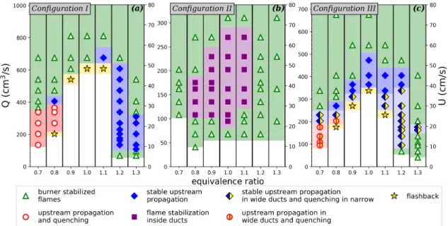
Experiments showed that depending on mixture equivalence ratio, flow rate and channels configuration, various dynamic flame behavior can be observed. We singled out seven different combustion regimes of the multi-channel burner. The placement of these regimes in equivalence ratio / flow rate plane are shown in Fig. 3. Besides mixture flow rate directly measured in experiments and plotted along left y-axis in Fig.3, the average inlet velocity U is laid off right y-axis. Mixture inlet velocity is defined as U = Q/Sv, where Q is
mixture flow rate and Sv is the area of voids in the inlet section of the corresponding
multi-channel burner configuration. For configurations I-III this area is equal to 7 · 0.3 · a, 7 · 0.1 · a and (4 · 0.3 + 3 · 0.1) · a cm2, correspondingly, where a = 6 cm is the width of quarts plates forming channels walls. In the case of equally sized channels, U can be also treated as average mixture velocity at the inlet of each channel. However for the channels of different size (configuration III) U is only some nominal velocity defined as described above.
At high flow rates the flames are stabilized at the channels outlets (triangles in Fig. 3). In xy-plane (see Fig. 1) the flames are attached to the channels rims and have concave shape with the tip directed in the flow direction as shown in Fig.4a. Herewith, these torches shape is almost independent on z-coordinate. In the mixed channels configuration
Fig. 3. Experimental regime diagrams for multi-channel burner configurations I-III.
III the height of the flames stabilized at the wider channels outlets is higher than that of the narrow channels. These observations are quite in line with numerically obtained velocity distributions shown in Fig. 2 which predict higher velocity in wider channels. Almost equal height of the torches above side and central channels indicates that experimental setup provide quite uniform mixture flow rates in the channels.
The height of torches stabilized at channels rims decreases with decrease of mix-ture flow rate. For relatively wide channels of 0.3 cm transverse size (configuration I) the further decrease of flow rate makes possible the flame penetration inside the multi-channel burner. Since the multi-channels size d0 = 0.3 cm is much less than quenching
dis-tance dcr ≈ 0.45 cm for φ = 0.7 the heat losses to the channels walls lead to the flame
quenching at some depth from the top of the burner (open circles in Fig. 3). For φ = 0.8, dcr ≈ 0.32 cm is comparable with d0 and stable upstream flame propagation was
experi-mentally observed (solid diamonds in Fig. 3). Photograph of upstream propagating flame is shown in Fig. 4b The average flame propagation velocity in this case is of the order of fractions of millimeters per second. Such velocities are typical for the low velocity regime of filtrational gas combustion (Babkin and Laevskii, 1987) and indicate strong gas-solid thermal coupling and heat recirculation (Zamashchikov, 2001; Zamashchikov and Minaev, 2001). In the range of equivalence ratios 0.9 ≤ φ ≤ 1.1, dcr > d0 and fast upstream flame
propagation with the velocities comparable with laminar burning speed is observed in the range of relatively small mixture flow rates. Due to the flame rapid achievement of the
Fig. 4. Photographs of the multi-channel burner in configuration I obtained for Q = 405 cm3/s (U = 32.1 cm/s) and φ = 0.7 (a), φ = 0.8 (b), φ = 1.2 (c).
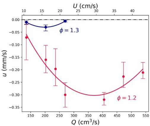
burner inlet section, typical for this combustion mode we termed it as flash-back (stars in Fig. 3). For the fuel rich mixtures with φ ≥ 1.2 the flame behavior at small flow rates differs from that of lean mixtures (φ ≤ 0.8). Namely, below the range of flow rates for which the stable upstream flame propagation is observed the flame does not quenched but demonstrate oscillating behavior (open diamonds in Fig. 3). These oscillations consist of a repeating sequence of the following processes: upstream flame propagation; flame quenching in the cold upstream part of the channel due to heat losses; filling of the chan-nel by unburned mixture; mixture ignition in the downstream section of the burner by secondary diffusion flame or by hot channels walls. Existence of the secondary diffusion flame is related with afterburning of the fuel remaining in the combustion products of fuel rich mixture. Oscillating flames inside the channels and secondary diffusion flame at the burner outlet can be seen in Fig. 4c. Flame pulsations described above are accom-panied with noticeable sound and have the same mechanism as FREI (flame repetitive extinction and ignition) combustion regime which was observed in narrow tubes with tem-perature gradient in the walls (Maruta et al., 2005). In the course of flame oscillations the channels walls are heated that results in upstream movement of the average flame front position with almost constant velocity. Figure 5 shows the dependencies of average flame propagation velocity on mixture flow rate obtained for two values of equivalence ratios φ = 1.2 and 1.3. As can be seen from Fig. 3a for the rest values of φ the stable upstream propagation either does not take place or observed in less than two data points. Average flame velocity (u) was calculated on the basis of discrete temporal dependency of average flame front position (xf(ti), i = 1..N ), obtained from successive photos of the flame as
u = (N − 1)−1PN −1
i=1 ui, where ui = (xf(ti+1) − xf(ti))/(ti+1− ti). Time intervals
be-tween consecutive frames were in the range 20 s ≤ ti+1− ti ≤ 60 s. Maximal and minimal
values of ui are depicted in Fig. 5 by error bars. As can be seen from Fig. 5 the speed
Fig. 5. Dependencies of average flame propagation velocity (u) on mixture flow rate (Q) obtained for configuration I and different equivalence ratios (φ)
inlet mixture velocity have U-shape form. Such behavior is typical for the low velocity regime of filtrational gas combustion (Babkin and Laevskii, 1987; Zamashchikov and Mi-naev, 2001). Finally, at extremely small flow rates (Q < 25 cm3/s (U < 2 cm/s)) the flame existence becomes impossible and combustion wave is extinguished immediately after removing of pilot flame.
Regime diagrams obtained for the set of equally sized narrow channels of transverse size 0.1 cm (configuration II) significantly differ from those for wide channels with d0 =
0.3 cm (configuration I). Thus, for φ = 0.7, 1.2 and 1.3 flame penetration inside the chan-nels becomes impossible and only burner stabilized flames are observed over whole range of mass flow rates. It is worth to note, that d0 = 0.1 cm is significantly less than quenching
distance dcr(minφdcr ≈ 0.2 cm) in whole range of mixture equivalence ratios. Therefore,
it can be assumed that impossibility of flame penetration inside the set of narrow channels for the mixtures far from stoichiometric is related with increase of surface-to-volume ratio resulting in intensification of heat losses to the channels walls. In the range of equivalence
ratios from 0.8 to 1.1 and moderate mixture flow rates the flames propagate upstream and then settle inside the channels at certain distances from the burner interface. Although FREI phenomenon is observed, the average positions of flames inside the channels remain constant. In Fig. 3 this combustion mode is marked by rectangles. To make sure that av-erage flame positions are invariable in time, the long-term experiments were performed. These experiments shown that final average flame positions were establishing during 10-20 minutes transient period and then remained unchanged for up to 40 minutes till the end of experiment. Note that both flame propagation and quasi-stabilization stages are accompa-nied by sound which frequency can be estimated as 80-150 Hz. Noise emission is related with FREI-like oscillating behavior of the flames in the channels. Typical front and side views of the multi-channel burner operating in this quasi-stationary regime are shown in Fig. 6. In yz-plane all flames have cup-like shape. The edges of these ”cups” are attached to the top rims of the channels walls. The distance between the external burner surface and the deepest point of the flame is maximal in the central channel and minimal in the side channels. Similar flame shape was observed by Min and Shin (1991) in experiments on combustion in finite length honeycomb burner. It can be assumed that such flames shape is a result of heat losses from the burner sides to the ambient. Experiments shown that flame curvature depends on mixture equivalence ratio and flow rate. As can be seen from Fig. 6, the higher inlet mixture velocity, the deeper flames submergence in the channels. This observation is in a good agreement with basic combustion theory concepts asserting direct dependency of burning velocity on flame surface area. It may be concluded, that possibility of flame stabilization inside the multi-channel burner in the wide range of φ and Q is associated with effects of external heat losses (from the side walls and from the end faces of internal walls) and variation of flames surface area.
Experiments showed that for configuration III which consists of alternating wide and narrow channels upstream flames propagation with constant average velocity is possible under some conditions. At relatively high flow rates the combustion waves propagate in both wide and narrow channels (open and solid diamonds in Fig. 3 and Fig. 7b). Herewith, flame propagation in wide channels is almost uniform, while in narrow ducts repetitive flame extinction and re-ignition accompanied by popping sound can take place (open dia-monds in Fig. 3). In the ranges of equivalence ratios 0.7 ≤ φ ≤ 0.9 and 1.1 ≤ φ ≤ 1.3 fur-ther decrease of mixture flow rate Q leads to the flames quenching in the narrow channels. Nevertheless, stable upstream flame propagation in the wide channels are still observed. This combustion mode is marked by half-shaded diamonds in Fig. 3 and typical front view of the burner operating in this regime is shown in Fig. 7c. Measurements of the average flame propagation velocity have demonstrated the same qualitative behavior of u(Q) curve as was obtained for configuration I and shown in Fig. 5. It can be assumed that since the flame propagation velocity is lower at high flow rates, the heating of the narrow channels
Fig. 6. Front and side views of the flames stabilized inside the multi-channel burner in configuration II at φ = 1 and Q = 202.5 cm3/s (U = 48.1 cm/s) (a), Q = 135 cm3/s
(U = 32.1 cm/s) (b)
Fig. 7. Photographs of the multi-channel burner in configuration III obtained for φ = 0.8, Q = 405 cm3/s (U = 44.7 cm/s) (a); φ = 1.2, Q = 405 cm3/s (U = 44.7 cm/s) (b) and
φ = 1.2, Q = 270 cm3/s (U = 30 cm/s) (c)
by the flames in neighboring wide channels is more effective than those in the case of low mixture flow rates or equivalence ratios far from stoichiometry. As a result, the flame re-ignition from the channel walls supporting flame existence in narrow ducts is possible at high flow rates and is impossible at small Q. It seems likely that such heat support from the wide channels can explain the upstream flame propagation in narrow channels in config-uration III at φ = 1.2 which is impossible for configconfig-uration II (see Fig. 3) which consists of narrow channels only. Interestingly, that the range of mixture flow rates for which the upstream flames propagation is observed is much wider for the fuel rich mixtures. It may be related with the supporting influence of diffusion flame which is stabilized at the burner interface in the case of rich mixtures burning as discussed above (see Fig. 7b).
differently sized channels have shown that flames get into the narrow ducts first. For some transition period the separating walls are heated by the flames in narrow channels and combustion waves start to penetrate in the wide channels too. Such behavior is expectable, taking into account numerical predictions of velocity flow field (Fig. 2) which point out to lower mixture velocity at the outlet of narrow channels compared with velocity at the exit of wide channels.
4.2
Numerical simulations
Regime diagrams obtained numerically for the examined configurations I-III and lean mix-tures are shown in Fig. 8. Here, to mark different combustion regimes the same symbols as in Fig. 3 are used. For sake of comparison with experimental data, flow rate Q in Fig. 8 was calculated by using the given value of inlet mixture velocity provided by boundary conditions and geometrical dimensions of multi-channel burner taken from experiments.
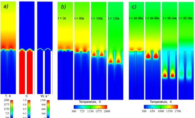
At high flow rates the flames are stabilized at the outlets of the channels (triangles in Fig. 8). Distributions of temperature, fuel concentration and reaction rate typical for this combustion mode are shown in Fig. 9a. These numerical results reproduce burner stabi-lized flames which were observed experimentally and shown in Fig. 4a and Fig. 6a. For the burner configuration I and moderate flow rates the flames penetrate inside the channels and propagate in upstream direction with a constant speed (solid diamonds in Fig. 8) as shown in Fig. 9b. The flame propagation velocity evaluated for the case presented in Fig. 9b is 0.2 mm/s, while experimentally measured value for φ = 0.8 and Q = 405 cm3/s (U = 32.1
Fig. 9. Temperature, concentration and chemical reaction rate distributions for different combustion modes in configuration I calculated for φ = 0.8, Q = 320 cm3/s (U = 25.4 cm/s) (a), Q = 220 cm3/s (U = 17.5 cm/s) (b) and Q = 65 cm3/s (U = 5.2 cm/s)
(c)
cm/s) is 0.22 mm/s. Thus, numerical and experimental values of propagation velocity co-incide well, while flow velocity in numerical simulations is underestimated. This result is typical for thermal-diffusion models which were found to produce qualitative results but underestimate velocities in microchannel systems (Maruta et al., 2005; Zamashchikov and Minaev, 2001). At low flow rates the flames penetrate into the channels and then are ex-tinguished (open circles in Fig. 8) due to the increasing heat flux from the gas to the cold channels walls. Flame dynamics typical for this case is shown in Fig. 9c.
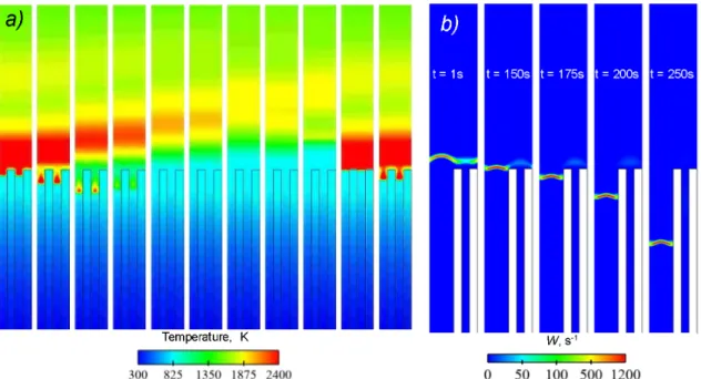
In a good qualitative agreement with the experimental data, the flames in configura-tion II are basically stabilized at the outlet of the channels. Only for near-stoichiometric mixtures, the flame penetration inside the burner is possible (rectangles in Fig. 8). Flame dynamics in this case includes following stages. At first, the flames are stabilized at the channels outlets. At this stage, lasting 5-15 minutes, the flames heat the channels walls. After that, the flames start to penetrate into the channels. Herewith, periodic flame extinc-tion inside the channels and flame re-igniextinc-tion at the channels outlets are observed. The
Fig. 10. Temporal evolutions of temperature distribution for channels configuration II calculated for φ = 0.9, Q = 220 cm3/s (U = 52.4 cm/s) with ∆t = 2.5 ms (a) and chemical reaction rate distribution in configuration III for φ = 0.9, Q = 110 cm3/s (U =
26.2 cm/s) (b)
distance between the outlet of the channels and the extinction point increases with time until being stabilized at some constant value after 10-20 minutes period. From this time on, the quasi-stationary combustion mode characterized by FREI-like oscillations with constant amplitude is established. The sequence of temperature distributions in the course of one period of such oscillations is shown in Fig. 10a.
It is necessary to notice, that in the absence of radiative heat losses from the channels walls end faces the quasi-stationary regime is not realized and upstream propagation of oscillating flames with constant average velocity take place. Hereby, the radiative heat losses from the walls end faces can provide stabilization of the average flame front position inside the multi-channel burner. These numerical results suggest that the presence of side heat losses leading to the curved flame shape as discussed in previous section (see Fig. 6) is not necessary condition for submerged flame stabilization. Perhaps, such stabilization may be ensured by radiation from burner end faces only and this combustion regime may be observed even in large or heat insulated multi-channel or porous burners.
For channels configuration III the flame behavior is similar to that in configuration I, with the exception that flames are penetrated inside wide channel only, and extinguished in
Fig. 11. Non-dimensional temperature (T ) and concentration (C) distributions along cen-tral lines of wide (solid lines) and narrow (dashed lines) channels and cencen-tral wall tem-perature profile (Θ). The channels area is on the left, while the free space to the right of the vertical dot-dashed line. Results were calculated for channels configuration III for φ = 0.8, Q = 267 cm3/s (U = 29.7 cm/s) (a), Q = 167 cm3/s (U = 18.6 cm/s) (b) and
Q = 67 cm3/s (U = 7.5 cm/s) (c).
narrow ones (half-shaded diamonds in Fig. 8). Figure 10b demonstrates temporal variation of chemical reaction rate distribution typical for this combustion mode.
Comparison of the experimental and numerical regime diagrams shows that reduced thermal-diffusion model describes main features of combustion in the multi-channel sys-tem. The placement of different combustion regimes in equivalence ratio / flow rate plane is also described well by the proposed model. At the same time, present numerical simula-tions do not reproduce flame penetration in both wide and narrow channels in configuration III as was observed in experiments (open diamonds in Fig. 3). However, this combustion mode was numerically obtained for alternating channels of transverse size 0.4 and 0.2 cm. This indicates that although the applied model is limited to qualitative predictions, it is able to reproduce all experimentally observed combustion modes. Quantitative numerical results are of interest, however detailed simulations seem to be extremely time-consuming due to the wide range of spatial and time scales and great characteristic times of the pro-cess (10-50 minutes). Hence, proposed mathematical model may be useful for prediction of the flame behavior in such systems in a wide range of problem parameters.
On the basis of qualitative agreement between experimental data and the results ob-tained in the frame of reduced model (1)-(3) one can suggest that main physical mech-anisms determining flame dynamics in such system are thermal-diffusion mechmech-anisms. This conclusion is expectable taking into account previous success of thermal-diffusion models in qualitative description of similar systems (Maruta et al., 2005; Zamashchikov
and Minaev, 2001). Therefore main features of flame behavior in multi-channel burner can be explained on the basis of burning velocity concept and analysis of temperature distri-butions in gas and solid phases and heat fluxes between them. Really, let us examine four main flame modes described above, namely: burner stabilized flames; upstream propagat-ing flames; flames stabilized inside the burner and quenchpropagat-ing followpropagat-ing upstream flame propagation. Burner stabilized flames are observed in the range of high flow rates (trian-gles in Fig. 3 and 8). Results of numerical simulations suggest that flame stabilization is caused by ineffective heat exchange between gas and solid phase and additional heat losses to the channel walls. It can be clearly seen from temperature distributions along the central axis of the channel and the wall which are shown in Fig. 11a. Wall temperature Θ in this case is close to the ambient one and heat losses from the reaction zone to the walls are significant. As a result burning velocity turns out to be less than flow velocity and flames can not penetrate the channels, but stabilize near their outlets. Decrease in flow velocity leads to the approaching of the flame front to the channels outlets which in turn leads to the heating of the channel walls. Heat exchange between gas and solid phase results in preheating of unreacted mixture and in increase of burning velocity. This heat recirculation mechanism described in (Babkin and Laevskii, 1987; Zamashchikov and Minaev, 2001) and demonstrated by Fig. 11b underlies the upstream propagating flames mode(diamonds in Fig 3 and 8). Further decrease of flow velocity leads to the increase of flame propagation velocity and to decrease of its residence time. As is seen from Fig. 11c, fast flame propagation results in decrease of wall temperature Θ and weakness of heat recirculation. Finally, increased heat losses to the channels walls quench the flame what correspond to upstream propagating and quenching regime (circles in Fig. 3 and 8). Notice that imbalance between heat fluxes, burning velocity and mixture flow rate manifests itself in FREI-like oscillations in the same manner as was described in (Maruta et al., 2005; Sirotkin et al., 2017). Numerical simulations showed, that in this case, all above described mechanisms of flame behavior take place in average but accompanied with FREI-like pulsations. Lastly, the flame stabilization inside the burner is fully deter-mined by the balance between heat released by the flames and external heat losses from the burner external surface. As it was mentioned before, numerical simulations showed that radiative heat loss is necessary mechanism for submerged stabilization. Results of present simulations assuming infinite width of the system and, therefore, absence of side heat losses demonstrate the possibility of flame quasi-stabilization inside the system at the expense of radiative heat losses from the channels walls end faces only. Such prediction is difficult to obtain by means of experimental studies. At the same time this information may be of interest for understanding of the processes in large-scale porous burners.
5
Concluding remarks
Experiments and numerical simulations demonstrate a big variety of combustion regimes in the multi-channel burner including burner stabilized flames, upstream propagating flames and flames stabilized under the burner external surface. Flame behavior depends on mix-ture flow rate, equivalence ratio and size of the channels. The placement of different combustion regimes in equivalence ratio / flow rate plane is plotted on the basis of ex-perimental observations and numerical simulations. It is found that in the wide range of moderate flow rates and equivalence ratios the flame penetration and subsequent upstream propagation is accompanied with pulsations. These pulsations consist in repetitive flame ignition, upstream propagation and extinction, in perfect analogy to FREI phenomenon (Maruta et al., 2005). Flame pulsations are the origin of noticeable sound produced by the multi-channel burner. Despite fast motion of oscillating flame fronts, the average propa-gation velocity of the combustion wave is typically of the order of mm/s. This fact points to the strong thermal coupling between gas and solid phase which is typical for filtrational gas combustion (Babkin and Laevskii, 1987). Moreover, it is found that under some condi-tions (channels size less than quenching distance, near stoichiometric mixtures, moderate mixture flow rates) average flame position can be stabilized on the some depth from the multi-channel burner outlet. Numerical and experimental results suggest that possibility of such submerged stabilization is associated with radiative heat losses from the burner walls. For the multi-channel burners consisting of differently sized channels, obtained results al-low expecting flame penetration in the narrow channels first. After that, heat support from the narrow channels initiates the entering of the flames in wide channels.
It should be noted that despite a number of simplified assumptions mathematical model applied in this study allow qualitatively reproduce all experimental findings listed above. It can be assumed that flame behavior in such systems is mainly determined by thermal effects, external heat losses and simple hydrodynamic reasons valid for non-reactive flows rather than detailed chemical kinetics or hydrodynamic instabilities. At the same time, ap-plied assumptions are valid for the lean mixtures and for the systems consisting of infinite number of channels. Thus, the expansion of the flame penetration limits for the fuel rich mixtures related with supporting influence of the secondary diffusion flame was observed experimentally but did not described numerically.
Information on flame topology and dynamic behavior of combustion wave in the multi-channel system may be useful for understanding of fundamental mechanisms of flame penetration and propagation in the porous burners. Thus, presented results on FREI-type flame oscillations may provide possible explanation of the noise frequently appearing in porous burners. Experimental and numerical results on submerged flame stabilization and corresponding discussion may be relevant for the case of filtrational gas combustion.
Acknowledgments
The study was supported financially by the Ministry of Education and Science of Russian Federation (project RFMEFI58417X0031).
References
Abdul Mujeebu, M., Abdullah, M. Z., Abu Bakar, M. Z., A., M. A., and Abdullah, M. K. (2009). Applications of porous media combustion technology - a review. Applied En-ergy, 86(9):1365–1375.
Aldushin, A. P. (1993). New results in the theory of filtration combustion. Combustion and Flame, 94:308–320.
Babkin, V. S. and Laevskii, Y. M. (1987). Seepage gas combustion. Combustion, Explosion and Shock Waves, 23(5):531–547.
Buckmaster, J. D. (1997). The effects of radiation on streched flames. Combustion Theory and Modelling, 1:1–11.
Coward, H. F. and Jones, G. W. (1952). Limits of flammability of gases and vapors. Bureau of Mines Bulletin, 503:155.
Fursenko, R., Minaev, S., Maruta, K., Nakamura, H., and Yang, H. (2010). Characteris-tic regimes of premixed gas combustion in high-porosity micro-fibrous porous media. Combustion Theory and Modelling, 14:571–581.
Hackert, C. L., Ellzey, J. L., and Ezekoye, O. A. (1999). Combustion and heat transfer model in two dimensional porous burners. Combustion and Flame, 116:177–191. Harris, M. E., Grumer, J., von Elbe, G., and Lewis, B. (1948). Burning velocities,
quench-ing, and stability data on non-turbulent flames of methane and propane with oxygen and nitrogen. 3rd Symposium on Combustion, Flame and Explosion Phenomena, 3(1):80– 89.
Hashemi, S. M. and Hashemi, S. A. (2017). Flame stability analysis of the premixed methane-air combustion in a two-layer porous media burner by numerical simulation. Fuel, 202:56–65.
Howell, J. R., Hall, M. J., and Ellzey, J. L. (1996). Combustion of hydrocarbon fuels within porous inert media. Progress in Energy and Combustion Science, 22(2):121–145.
Hsu, P. F., Evans, W. D., and Howell, J. R. (1993). Experimental and numerical study of premixed combustion within nonhomogeneous porous ceramics. Combustion Science and Technology, 90:149–172.
Janvekar, A. A., Miskam, M. A., Abas, A., Ahmad, Z. A., Juntakan, T., and Abdullah, M. (2017). Effects of the preheat layer thickness on surface/submerged flame during porous media combustion of micro burner. Energy, 122:103–110.
JUNKERS (1998). (bosch thermotechnik), information brochure, wernau.
Kakutkina, N. A. and Babkin, V. S. (1998). Characteristics of stationary spherical waves of gas combustion in inert porous media. Combustion, Explosion and Shock Waves, 34:123–132.
Khanna, R., Goei, R., and Ellzey, J. L. (1994). Measurements of emissions and radia-tion for methane combusradia-tion within a porous medium burner. Combusradia-tion Science and Technology, 99:133–142.
Kotani, Y. and Takeno, T. (1982). An experimental study on stability and combustion characteristics of an excess enthalpy flame. Symposium (international) on Combustion, 19:1503–1509.
Lee, D. K. and Noh, D. S. (2016). Experimental and theoretical study of excess enthalpy flames stabilized in a radial multi-channel as a model cylindrical porous medium burner. Combustion and Flame, 170:79–90.
Li, J., Wang, Y., Chen, J., Shi, J., and Liu, X. (2016). Experimental study on standing wave regimes of premixed h-2-air combustion in planar micro-combustors partially filled with porous medium. Fuel, 167:98–105.
Liu, J. F. and Hsieh, W. H. (2004). Experimental investigation of combustion in porous heating burners. Combustion and Flame, 138(3):295–303.
Liu, Y., Fan, A., Yao, H., and Liu, W. (2015). Numerical investigation of filtration gas combustion in a mesoscale combustor filled with inert fibrous porous medium. Int. J. Heat Mass Transfer, 91:18–26.
Lucio, T. and Fernandes, E. (2016). Rich-lean flame interaction in a lamella-type burner. Combustion Science and Technology, 188:416–438.
Maruta, K., Kataoka, T., Kim, N. I., Minaev, S., and Fursenko, R. (2005). Characteristics of combustion in a narrow channel with a temperature gradient. Proceedings of the Combustion Institute, 30:2429–2436.
Min, D. K. and Shin, H. D. (1991). Laminar premixed flame stabilized honeycomb ce-ramic. Int. J. Heat Mass Transfer, 34(2):341–356.
Minaev, S., Fursenko, R., Ju, Y., and Law, C. (2003). Stability analysis of near-limit stretched premixed flames. Journal of Fluid Mechanics, 488:225–244.
Mohamad, A. A., Ramadhyani, S., and Viskanta, R. (1994). Modelling of combustion and heat transfer in a packed bed with embedded coolant tubes. Int. J. Heat Mass Transfer, 37:1181–1191.
Parmentier, S., Braack, M., Riedel, U., and Warnatz, J. (2003). Modeling of combustion in a lamella burner. Combustion Science and Technology, 175:185–206.
Patankar, S. V. and Spalding, D. B. (1972). A calculation procedure for heat, mass and momentum transfer in three-dimensional parabolic flows. Int. J. Heat Mass Transfer, 15(10):1787–1806.
Sathe, S. B., Kulkarni, M. R., Peck, R. E., and Tong, T. W. (1990). An experimental and theoretical study of porous radiant burner performance. Twenty-Third Symposium (International) on Combustion, The Combustion Institute, Pittsburgh, PA, pages 1011– 1018.
Sirotkin, F., Fursenko, R., Kumar, S., and Minaev, S. (2017). Flame anchoring regime of filtrational gas combustion: Theory and experiment. Proceedings of the Combustion Institute, 36:4383–4389.
Smucker, M. T. and Ellzey, J. L. (2004). Computational and experimental study of a two-section porous burner. Combustion Science and Technology, 176:1171–1189.
Su, Y., Cheng, Q., Song, J., and Si, M. (2016). Numerical study on a multiple-channel micro combustor for a micro-thermophotovoltaic system. Energy Conversion and Man-agement, 120:197–205.
Terracciano, A. C., Oliveira, S., S., V. S., and Orlovskaya, N. (2017). Flow stabilized porous heterogeneous combustor. part ii: Operational parameters and the acoustic emis-sion. Fuel Processing Technology, 159:412–420.
Yang, H., Minaev, S., Geynce, E., Nakamura, H., and Maruta, K. (2009). Filtration com-bustion of methane in high-porosity micro-fibrous media. Comcom-bustion Science and Technology, 181:654–669.
Yilmaz, H., Cam, O., and Yilmaz, I. (2017). Effect of micro combustor geometry on combustion and emission behavior of premixed hydrogen/air flames. Energy, 135:585– 597.
Zamashchikov, V. V. (2001). An investigation of gas combustion in a narrow tube. Com-bustion Science and Technology, 166(1):1–14.
Zamashchikov, V. V. and Minaev, S. S. (2001). Limits of flame propagation in a narrow channel with gas filtration. Combustion, Explosion and Shock Waves, 37(1):21–29. Zhdanok, S. A., Dobrego, K. V., and Futko, S. I. (1998). Flame localization inside
axis-symmetric cylindrical and spherical porous media burners. Int. J. Heat Mass Transfer, 41:3647–3655.