九州大学学術情報リポジトリ
Kyushu University Institutional Repository
非加熱プロセスによる重質油の増進回収
ンゲレ, オドゥ, ピエール, ロナルド
https://doi.org/10.15017/1866290
出版情報:Kyushu University, 2017, 博士(工学), 課程博士 バージョン:
権利関係:
IMPROVED HEAVY OIL RECOVERY BY NON- THERMAL PROCESSES
Nguele Odou Pierre Ronald
KYUSHU UNIVERSITY
IMPROVED HEAVY OIL RECOVERY BY NON- THERMAL PROCESSES
A Doctoral Dissertation
Submitted to the Department of Earth Resources Engineering, Graduate School of Engineering, Kyushu University, Japan In Partial Fulfillment of the Requirements for the Degree of Doctor of
Philosophy In
Earth Resources Engineering
By
Nguele Odou Pierre Ronald
September, 2017
ABSTRACT
Heavy oil is defined as liquid petroleum of 20 to 10 °API gravity at reservoir conditions, and the crude of which API is less than 10°API is termed as extra heavy. Heavy and extra-heavy oil reserves consist approximately of 21 and 32% of total oil reserves respectively, while those of light to medium are estimated at 47 %. This means there is a substantial volume of heavy oil, which sits within the reach of existing oilfields. Most of these oils are trapped within the pore throats of shallow, small and thin matrices including low permeable siltstones, sandstone and carbonate reservoirs. In theory, the increment in oil, from these mature reservoirs, is obtained by implementing a technique referred as improved oil recovery (IOR). The IOR has been classified mainly into two groups that are thermal and non-thermal methods. The former, in which the heat is supplied to the reservoir in form of steam, has been preferred for heavy and extra heavy oils, because steam injection is strongly expected to decrease the mobility of the oil and augments thereby the production. To date, the production scheme is slowly disfavored primarily because of the cost of stem generation. On the other hand, a typical non-thermal method consists of injecting a fluid (slug) that reduces either the interfacial tension (IFT) or the viscosity of the residual oil. However, a poor propagation of the slug lowers the efficiency of these methods. The implementation of either of these techniques, in a candidate mature heavy oil reservoir, is inherent to its petro-physical properties and the characteristics of the residual oil.
The scope of this research considered two candidate heavy oil formations. The initial IOR screening highlights the possibility of gas-miscible (CO
2) and chemical-IOR respectively to petro-physics of the candidate formations and the properties of the residual oil. The motivation was not only to evaluate their potential, but also to highlight the technical challenges.
Ultimately, it was sought to propose a recovery scheme that increases the heavy oil production, while reducing associated energy cost. Both were investigated experimentally in this research.
This dissertation consists of six chapters.
Chapter 1 introduces the fundamentals of IOR, discusses on the various approaches in heavy
oil recovery. Therein is also detailed the mechanisms inherent to heavy oil production and the
screening criteria of IOR. The candidate formations, the properties of its untapped oils are
presented.
Chapter 2 investigates the potential of CO
2for the candidate formations, which was selected in respect of the petro-physical properties of the reservoir. The production was mimicked by injecting CO
2both at its sub-critical and super-critical state (sCO
2) in candidate heavy oils (API 11.5 and 16.6). Conducted in a PVT analyzing cell, the results showed that sCO
2has a better solvating potential than CO
2. The swelling of the candidate heavy oils increased in a linear fashion with the concentration of sCO
2and was altered by the presence of reservoir water. It was further shown that sCO
2promoted a stripping process of light fractions from the native oil during the development of the miscibility front, which was followed by the deposition of an appreciable amount of asphaltenes. This latter phenomenon was highlighted as major drawback for this IOR method. Further investigations in this regard revealed that not only the petro- physical properties of the candidate formation would dictate the concentration of aggregated asphaltene, but also the chemical composition of the crude oil and even the injecting conditions of sCO
2. If implemented in the candidate formation, it is shown that the injecting gas (sCO
2) would behave either as flocculent or coagulant. Subsequently, these properties would either control or enhance the amount of deposited asphaltene. It was concluded that sCO
2was potentially viable for a heavy oilfield provided that proper injection conditions were maintained.
However, given the initial concentration in asphaltene in the candidate heavy oils, sCO
2-IOR cannot be recommended.
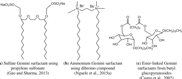
In Chapter 3, the heavy oil production, in respect of the physico-chemical properties of the candidate heavy oils, is investigated. Therein is introduced a new class of surfactants (Gemini surfactants). Two lyophilized cationic Gemini surfactants i.e. 12-3-12 and 16-3-16 were used to formulate the aqueous micellar slugs. Their inherent physico-chemical properties were subsequently investigated. These included the critical micelle concentration (CMC), the adsorption and the surface tension. Their potential for surfactant flooding were shown as they were able to achieve (i) an ultra-IFT (order of 10
-3mN/m), (ii) high water and oil solubilization and (iii) a relative low adsorption on sandstone and dolomite. More interestingly, those properties were found pronounced when the micellar slug, prepared from a Gemini surfactant with a longer hydrophobic alkyl chain (n=16), was used. Additionally, the micellar slugs showed an interesting potential as corrosion inhibitor by neutralizing the acidic materials generated as by-product during sCO
2-IOR.
Chapter 4 introduces the concept of cationic microemulsions and their relevance to oil
the alkyl chain of the primary surfactant, and the nature of the respective cosurfactant, (ii) the presence in divalent ions in the brine solution and (iii) the acidity of the residual oil. The rheology of the microemulsions revealed a pseudo-plastic behavior, which was altered by the formation salinity. Therein is also addressed the characterization of the cationic microemulsions.
Chapter 5 introduces a hybrid recovery-flooding scheme using microemulsions. The heavy production was performed by a series of core-flooding experiments, performed in Berea sandstone, representative of the formation rock. The production scheme consisted of the injection of microemulsion-gel type formulated exsitu, in water-flooded sandstone, at the trail of which low-saline water was injected. Conducted in the homogeneous Berea sandstones, up to 31% of the initial oil-in-place (IOIP) was recovered from the homogeneous water-flooded sandstone when the heaviest microemulsion formulation was injected. The oil recovery was lowered to 20.3% when the microemulsion was formulated from the micellar slugs prepared from the Gemini surfactants with the shorter alkyl chain. The microemulsion formulations prompted a series of chemical reactions with the native minerals and the residual petroleum fluids, which caused the formation of sludge in the effluent fraction. The sludge is believed to be the challenge in this recovery scheme. However, it was shown that altering the composition of the preflush water could mitigate the deposition.
Chapter 6 concludes this research by highlighting the feasibility of two methods. A comparative analysis and proposed solution in respect the inherent challenges are presented.
Further suggestions in regard of microemulsion-flooding and asphaltene deposition are
discussed.
ACKNOWLEDGEMENT
This work is dedicated to the memory of my late mother (Rose Nguele) and to my dad (Nguele Henri).
This research would have not been possible without guidance and the support of several individual who, in a way or another, have extended their valuable assistance.
My deepest gratitude goes to my supervisor Professor Kyuro Sasaki who has always been keen on sharing his experience, mentoring me and suggesting ever more fascinating and challenging ideas and concepts to work on.
I would like to acknowledge Professor Hiroshi Tashima for his critical comments.
I would like to thank Associate Professor Yuichi Sugai for his valuable help throughout my research. His assistance in supplying the materials and equipment during this work is greatly appreciated.
I would also like to acknowledge Professor Hikmat Said Al-Salim whom has been more than an academic advisor throughout my studies.
The financial support from the Ministry of Education, Culture, Sports, Science and Technology of Japan (MEXT) is acknowledged. My special gratitude goes to Japan Petroleum Exploration (JAPEX) and Lion LTD for kindly supplying the heavy oils and the cationic Gemini surfactants used in this research respectively.
I would also like to thank Brian Omondi, doctoral student at Kyushu University, for the collaboration and its valuable inputs and efforts for this work to be completed.
I am indebted to many of my family, friends and colleagues from REPS who through their sincere suggestions and fruitful discussions shaped this dissertation in so many ways.
In particular I would like to thank my sisters, Christiane, Florence and Marie-Paul whose moral
support has been crucial in the final stretch of the dissertation. A special wink to my brothers
Olivier and Yannick. This work would have not be complete without mentioning my fellows
Guillaume Doudou, Abu B. Jalloh, Ibrahim and many others whom I did not cite explicitly.
TABLE OF CONTENTS
ABSTRACT ………...i
ACKNOWLEDGEMENT ... iv
TABLE OF CONTENTS ... v
LIST OF FIGURES ... viii
LIST OF TABLES ... x
INTRODUCTION 1.1 Oil Production and Fundamentals of Improved Oil Recovery ... 11
1.2 Tertiary Oil Recovery for Heavy Oil Reservoirs ... 13
1.2.1 Thermal methods ... 14
1.2.2 Non-thermal methods... 16
1.3 Emerging IOR Technologies ... 18
1.3.1 In-situ conversion with electrical heating ... 18
1.3.2 Microemulsion flooding... 18
1.3.3 Nanofluid flooding ... 18
1.4 IOR Screening Criteria ... 18
1.5 Problem Statement and Research Objectives ... 20
1.5.1 Problem statement ... 20
1.6 Thesis Outline ... 21
Chapter 2. HEAVY OIL PRODUCTION BY SUPERCRITICAL CO
22.1 Fundamentals of Gas-Miscible Recovery ... 23
2.2 Improved Oil Recovery and Reservoir Thermodynamics ... 24
2.2.1 Three-phase equilibrium calculations ... 24
2.2.2 Thermodynamics of asphaltene deposition ... 24
2.3 Experimental Section ... 25
2.3.1 CO
2and sCO
2injection ... 25
2.3.2 Quantification of asphaltene in the candidate heavy oils ... 25
2.4 Phase Equilibria Results ... 26
2.4.1 CO
2solubility at sub- and supercritical conditions... 26
2.4.2 Oil foaminess ... 28
2.5 Asphaltene Aggregation and Deposition ... 30
2.5.1 Effect of the slug composition ... 32
2.5.2 Pseudo-equilibrium temperature ... 34
2.6 Summary ... 36
HEAVY OIL PRODUCTION BY CHEMICAL METHODS
3.1 Chemical Recovery: Background ... 38
3.2 Gemini Surfactants: A New Class of Surfactants for Heavy Oil Recovery ... 39
3.3 Specific Properties of Cationic Gemini Surfactants in Respect of Improved Oil Recovery 41 3.3.1 Critical micelle concentration ... 41
3.3.2 Solubilizing and emulsifying potential ... 42
3.3.3 Corrosion inhibitor ... 42
3.4 Experimental Section ... 43
3.4.1 Materials ... 43
3.5 Methods ... 44
3.5.1 Preparation of aqueous slugs from cationic Gemini surfactants ... 44
3.6 Physico-Chemical Analysis of Aqueous Micellar Slugs ... 47
3.6.1 Surface tension and critical micelle concentration ... 47
3.6.2 Evaluation of solubilization potential of cationic Gemini surfactants ... 52
3.6.3 Adsorption study at solid/slug interface ... 53
3.6.4 Inhibiting potential of cationic Gemini surfactants ... 55
3.7 Summary ... 56
PROPERTIES OF CATIONIC MICROEMULSIONS 4.1 Background ... 57
4.2 Experimental Section ... 58
4.2.1 Materials ... 58
4.2.2 Methods... 58
4.3 Phase Behavior of Micellar Slugs ... 59
4.3.1 Salinity scan test ... 59
4.3.2 Presence of divalent ions ... 61
4.3.3 Effect of crude oil acidity and cosurfactant ... 63
4.3.4 Effect of reservoir temperature ... 65
4.4 Mechanistic Analysis and Characterization of Microemulsions ... 65
4.4.1 Rheology of microemulsions ... 65
4.4.2 Particle size analysis ... 68
4.5 Summary ... 71
EXPERIMENTAL EVALUATION OF HEAVY OIL PRODUCTION BY MICROEMULSION FLOODING 5.1 Theoretical Approach ... 72
5.2 Experimental Section ... 74
5.2.1 Reservoir fluids and slugs ... 74
5.2.2 Methods... 75
5.4 Oil Recovery ... 81
5.4.1 Heavy oil production from conventional cores ... 81
5.4.2 Heavy oil production from unconventional cores ... 82
5.5 Wettability Alteration ... 84
5.5.1 Relative permeability ratio ... 84
5.5.2 Effect of preflush composition ... 85
5.6 Alteration of Heavy Oil Production by Microemulsion-Oil-Rock Interactions ... 87
5.6.1 Ion tracking and its influence of formulation performance ... 87
5.6.2 Formation of clusters ... 92
5.7 Summary ... 94
SUMMARY and CONCLUSIONS 6.1 Summary ... 96
6.2 Heavy Oil Production in Respect of the Petro-physical Properties of the Candidate Formations ... 96
6.3 Heavy Oil Production in Respect of the Physico-Physical Properties of the Candidate Heavy Oils ... 98
6.3.1 Cationic Gemini surfactants for improved heavy oil recovery ... 98
6.3.2 Laboratory evaluation of microemulsion flooding for heavy oils ... 99
6.4 Future Challenges and Considerations ... 100
REFERENCES ... 102
LIST OF FIGURES
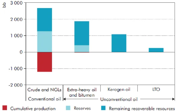
Fig. 1.1 Estimation of technically recoverable heavy oils and natural bitumen ... 11
Fig. 1.2 Different stages of an oilfield life... 12
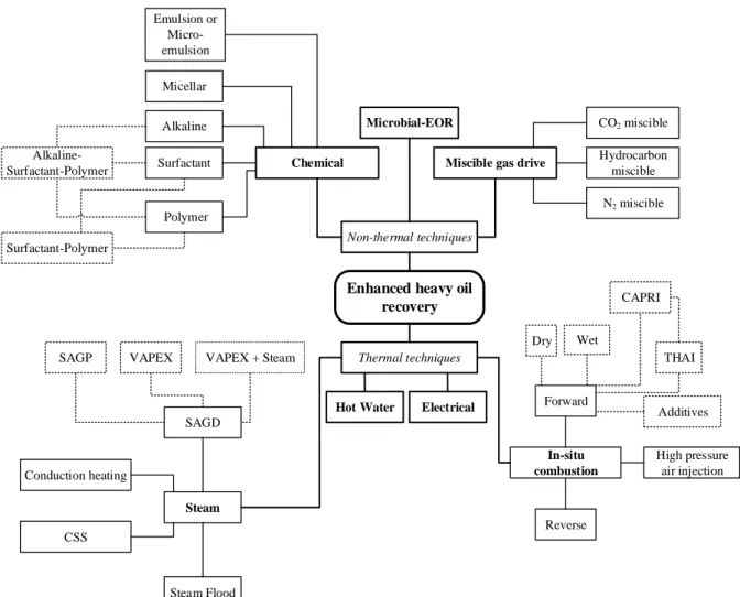
Fig. 1.3 An overview of enhanced oil recovery method... 14
Fig. 1.4 Schematic representation of heavy oil recovery by thermal methods ... 15
Fig. 2.1 Solubility of CO
2in heavy crude oils at sub- and supercritical conditions and effect of reservoir water ... 27
Fig. 2.2 Heavy oil swelling during sub- and supercritical CO
2injection ... 29
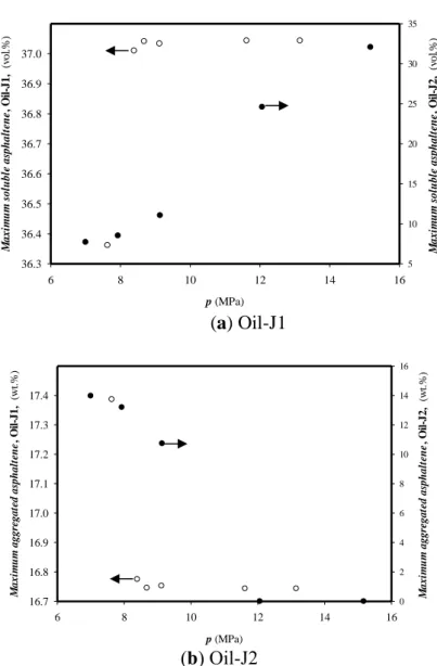
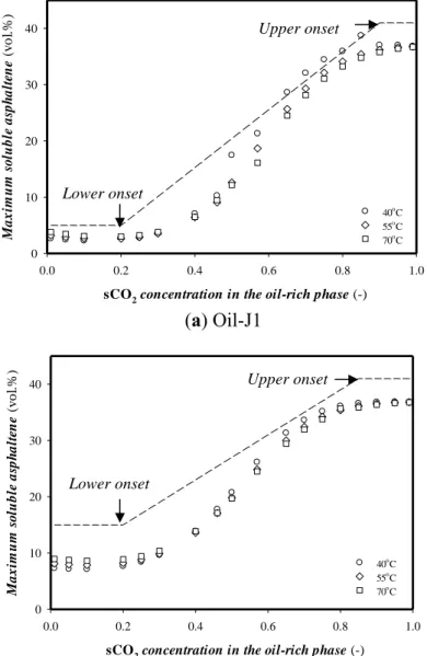
Fig. 2.3 Estimated maximum soluble and aggregated asphaltene ... 31
Fig. 2.4 Sensitivity analysis of slug purity on asphaltene solubility ... 32
Fig. 2.5 Onset concentrations as function of MMP ... 34
Fig. 2.6 Effect of reservoir temperature on asphaltene aggregation ... 35
Fig. 3.1 A schematic representation of a typical chemical-EOR ... 38
Fig. 3.2 Chemical arrangement of dimeric Gemini surfactant showing the position of spacer ... 40
Fig. 3.3 A sample representation of different types of Gemini surfactant representation ... 40
Fig. 3.4 Chemical structure of investigated cationic Gemini surfactants ... 43
Fig. 3.5 Solubility of 12-3-12 and 16-3-16 in different base fluids ... 45
Fig. 3.6 Experimental determination of CMC of cationic slugs ... 48
Fig. 3.7 CMC and surface tension alteration as function of the dielectric constant of micellar slugs ... 49
Fig. 3.8 Effect of salt concentration and divalent ions on CMC and surface tension ... 50
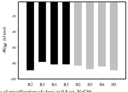
Fig. 3.9 Energy of micellization of slugs at 0.5 wt. NaCl% ... 51
Fig. 3.10 Evaluation of solubilizing potential of H
5... 52
Fig. 3.11 Static adsorption of R
4in Berea sandstone ... 54
Fig. 3.12 Infrared absorption spectra of Oil-J1, (Oil-J1+2 wt.% NaCl+sCO
2) and (Oil- J1+sCO
2+H
5); adapted from (Nguele et al., 2016c) ... 55
Fig. 4.1 Schematic representation of Winsor microemulsion... 58
Fig. 4.2 Solubilization plots as a function of salinity of Oil-J2 ... 60
Fig. 4.3 Solubility plots of Oil-J1 and Oi-J2 as function of salinity and formation hardness . 62 Fig. 4.4 Crude oil acidity as function of average carbon number ... 64
Fig. 4.5 Alteration of optimal salinity by the crude oil acidity ... 64
Fig. 4.6 Effect of reservoir temperature on the optimal salinity; 44.4% Oil-J1+11.2 % H
5+
44.4% NaCl ... 65
Fig. 4.7 Rheology of microemulsions at reservoir temperature ... 66
Fig. 4.8 Effect of salinity concentration on the rheology of microemulsions ... 67
Fig. 4.9 Particle size distribution of microemulsions ... 68
Fig. 4.10 Sensitivity analysis of reservoir acidity on clustering and particle size distribution 70 Fig. 5.1 Schematic representation of oil mobilization by microemulsion flooding ... 72
Fig. 5.2 Schematic representation of microemulsion flooding apparatus ... 76
Fig. 5.3 Pseudo-ternary diagram of (Oil-J2-0.1 wt. % NaCl -micellar slug) ... 79
Fig. 5.4 Rheology of microemulsion-gel type at 55
oC ... 80
Fig. 5.5 Oil recovery from conventional Berea sandstones ... 82
Fig. 5.6 Oil recovery from unconventional sandstone cores ... 83
Fig. 5.7 Wettability alteration as function of water saturation ... 85
Fig. 5.8 Oil saturation alteration by change in preflush composition ... 86
Fig. 5.9 Emulsion and water cuts from conventional sandstones ... 87
Fig. 5.10 Ion tracking and effect of flooding fluid ... 88
Fig. 5.11 Sludge deposition at the water breakthrough ... 89
Fig. 5.12 Dynamic adsorption during microemulsion flooding ... 91
Fig. 5.13 Particle size distribution at the different stages of oil production ... 93
Fig. 5.14 Modeling of particle clustering ... 94
LIST OF TABLES
Table 1.1 Advantages and drawbacks of sCO
2... 16
Table 1.2 Screening criteria in respect of petro-physical properties of formation and candidate oil characteristics ... 19
Table 1.3 Presentation of the candidate heavy oilfields ... 21
Table 2.1 Experimental conditions for CO
2injection ... 25
Table 2.2 Results of aggregated asphaltene during sCO
2injection ... 31
Table 3.1 Basic properties of some bis-quaternary alkylammonium chlorides ... 41
Table 3.2 Physical properties of investigated cationic Gemini surfactants ... 43
Table 3.3 Chemical composition and properties of brine solutions ... 44
Table 3.4 Physico-chemical properties of micellar slugs ... 45
Table 3.5 CMC and surface tension of investigated slugs in low saline water ... 49
Table 3.6 Summary of static adsorption experiments ... 54
Table 3.7 Results of acidity inhibiting factor ... 56
Table 4.1 Summary of optimal salinity from the salinity scan tests ... 61
Table 5.1 Composition of synthetic formation waters ... 74
Table 5.2 Berea sandstone properties ... 75
Table 5.3 Mineralogy of Berea sandstone ... 75
Table 5.4 Summary of injection assays ... 77
Table 5.5 Composition and properties of microemulsion-gel type ... 81
INTRODUCTION
1.1 Oil Production and Fundamentals of Improved Oil Recovery
Crude oil refers to a mixture of hydrocarbons, yellow to black in color, of which density and viscosity are variable. The former is defined quantitatively by a parameter known as API (i.e.
American Petroleum Institute). The latter (i.e. viscosity) is a key parameter as far as the production of an oilfield is concerned. In general, the crude oil is classified either by its oiliness (i.e. API) or the chemical composition. Thus, an API that ranges from 32
oto 40
odenotes a light crude oil. Medium crude oil has an API, which ranges from 27
oto 32
o. On the other hand, an API, from 8 to 14, characterized heavy oil. For any value of API below 8
o, the crude oil is an extra-heavy oil (Simanzhenkov and Idem, 2003). In 1997, Rogner (1997) reported approximately 3,396 billion of barrels of heavy oils and 5,505 billion of barrels (bbl) of extra- heavy oils trapped within the reach of existing oilfields. Over two decades, these values have been decreasing to half showing thereby the interest in these fossil resources (Fig. 1.1).
Conventionally, the life of a producing oil field is staged in three major stages including a primary, a secondary and a tertiary stage (Fig. 1.2). During the early stage of an oilfield, the natural resources are brought to the surface through the reservoir natural drive.
Fig. 1.1 Estimation of technically recoverable heavy oils and natural bitumen; from (IEA,
2013)
Fig. 1.2 Different stages of an oilfield life; modified from Kokal and Al-Kaabi (2010)
Five crucial parameters should be highlighted here in order to understand the underlying mechanisms of the oil production. These include (1) solution-gas drive, (2) gas-cap drive, (3) water-drive, (4) gravity drainage and (5) the mixed drive (Donaldson et al., 1989; Green and Willhite, 1998). A solution-gas drive is predominant if the drive energy is supplied by the expansion of the dissolved gases in the oil and water, which is reportedly the case for most of the oil reservoirs. If the reservoir is under-saturated, i.e. no free gas (es) dissolved within the oil, the driving force is provided only by the bulk expansion of the formation rock and liquids.
It is worth mentioning that most of the heavy oil reservoirs are under-saturated, thus subject to this mechanism at the early life of the production. A gas-cap drive dominates the production in a primary recovery process when the gas-cap (that is the segregated gas overlying the oil deposit) expands. The trapped gas pushes the gas-oil contact downwards. As the production continues, it reaches the producing wells. As a consequence, the gas-oil ratio (GOR) increases substantially and more oil is produced.
Alagorni (2015) reviewed that the primary recovery by gas-cap drive mechanism could reach up to 40 % of the Initial Oil-in-Place (IOIP). If, however, the candidate oilfield has an aquifer, the governing mechanism is likely to be a water-drive. In this mechanism, the oil is produced as a result of the expansion of water into the formation, forcing the oil to move upwards. In this case, the production will decline at the water breakthrough. The fourth mechanism is the gravity drainage mechanism in which the density difference between the petroleum fluids (oil, gas and water) results in their natural segregation in the reservoir that forces further the oil to move upwards. This mechanism is commonly encountered in light crude oil formation.
Unfortunately, the gravity drainage mechanism yields usually a low oil recovery and tends to be used in combination with other drive mechanisms (Donaldson et al., 1989). The last drive is a combination of aforementioned techniques, which tends to be encountered when none of aforementioned mechanisms, discussed above, prevails.
Primary Recovery Secondary recovery Tertiary recovery
Non-thermal Thermal
Water flooding Pressure maintenance Internal
energy drive
Artificial lift
Less than 30% of stranded oil is
recovered Up to 50% of stranded oil is recovered Up to 80% of stranded oil is recovered
Underlying mechanisms Underlying mechanisms Underlying mechanisms
Regardless the mechanisms(s) that dictate(s) the early life of an oilfield, the recovery is generally low. Most of the oilfields reported a recovery as high as to 30% of IOIP during the primary recovery process, which means that there is a substantial amount of oil trapped underground. In order to boost the production, it is routinely accepted to inject a fluid (usually water) that maintains the pressure within the formation and increases subsequently the oil production. This technique is referred as secondary production. In this approach, water is usually preferred. Few notable heavy oilfields, specially located in the United Kingdom, have successfully implemented water-flooding (Jayasekera and Goodyear, 2000). The problem with water flooding lies mainly on the tendency of the water to channel and to override the residual oil primarily because of its low viscosity. These phenomena, often concomitant, rend the implementation of water flooding less effective or even not applicable to heavy oil and extra- heavy oil reservoirs. Nevertheless, where applicable, a classical water flooding could displace up to 50 % of IOIP (Mai et al., 2009). Furthermore, in a heavy oil reservoir in which the primary recovery is governed by gas cap drive, the secondary recovery technique considers rather the injection of a gas. Technica, the gases, produced at the first stage, are routinely injected back in the candidate formation. This method is known as gas flooding. It could be conjectured therefore that the choice of the secondary recovery method depends to a certain extent on the driving force during the early life of the reservoir.
The last stage of the production life of an oilfield is the tertiary recovery. This stage is implemented when the primary and the secondary recovery processes have become inefficient and economically not beneficial. The stage is termed as improved oil recovery (IOR) or enhanced oil recovery (EOR). Although, both terms are used interchangeably, they imply the increment in amount of oil. To be more accurate, IOR is the general term to designate any means implemented after secondary process that increases considerably the amount of oil recovered. The terminology EOR is more specific. It defines a technique (or a combination of techniques) implemented to decrease the residual oil saturation and increases subsequently the amount of produced oil (Thomas, 2008).
1.2 Tertiary Oil Recovery for Heavy Oil Reservoirs
Over the past decades, the extraction and the production of heavy and extra-heavy oils have
relied on cold production despites the wide range of existing EOR methods. Fig. 1.3is an
overview of EOR methods for heavy and extra-heavy oils.
Fig. 1.3 An overview of enhanced oil recovery method; adapted from Thomas (2008) 1.2.1 Thermal methods
Thermal methods are the most advanced techniques among EOR methods, as long as the field experience and technology are concerned. They are best suited for heavy oils and tar sands. In these methods, the heat is supplied to the reservoir and tends to favor the vaporization of some of the oil. The supplied heat could be in form of vaporized water (steam), which is injected continuously into the oil layer (Fig. 1.4a).
However, steam-EOR is sensitive to the geometry and the petro-physical properties of the candidate formation. The steam creates, within the oil layer, a steam zone that not only lowers the viscosity of the heavy oil, but also increases the driving pressure for the oil to move (Shah et al., 2010). Some heavy oilfields have reported that when the heat (therein steam) was supplied in a cyclic manner Fig. 1.4b), the production increased quickly. The injection of high- pressure steam, followed by a soaking stage yielded a rapid payout with a recovery ranging from 10 to 40 % of IOIP. Steam assisted gravity drainage (SAGD) is another thermal method
Enhanced heavy oil recovery
Thermal techniques Non-thermal techniques
Chemical Miscible gas drive
CO2 miscible
N2 miscible Hydrocarbon
miscible Microbial-EOR
Emulsion or Micro- emulsion Micellar
Alkaline- Surfactant-Polymer
Surfactant-Polymer
Surfactant
Polymer Alkaline
Conduction heating
CSS
Steam
Steam Flood SAGD
In-situ combustion
Forward
High pressure air injection Additives Dry
Reverse Wet
CAPRI
THAI
SAGP VAPEX VAPEX + Steam
Electrical Hot Water
(a) Steam flooding (b) Cyclic Steam Stimulation
(c) Steam Assisted Gravity Drainage (d) In-situ combustion
Fig. 1.4 Schematic representation of heavy oil recovery by thermal methods; adapted from Shah et al (2010)
Its working principle, schematized in Fig. 1.4c, is quite similar to that of steam flooding at the difference of the steam chamber (Sasaki et al., 1999). This technique works best when the oil mobility is low, as steam channels are less likely to form. Unfortunately, this EOR method suffers also from its sensitivity to formation parameters including the thickness and the heterogeneity. In order to overcome these issues, modified forms of SAGD have been investigated including VAPEX that uses rather a solvent gas (or a mixture of solvents) to create a vapor chamber (Cuthiell et al., 2006). The vapor plays the same role as the steam chamber.
Other variants include Steam and Gas Push (SAGP).
Also, it is possible to generate the heat in-situ, i.e. within the oil-bearing matrix (Fig. 1.4d).
In this case, the EOR is referred as in-situ combustion, which consists of the injection of a hot
air (or oxidizing gas) is injected on the oil bearing matrix (Selby et al., 1989). The contact
between the two fluids sparks a combustion that further supplies the thermal energy, which
prompts further the oil viscosity reduction. However, the low viscosity of the gas that overrides
the oil is reported to be a major drawback for this method. The density difference between the oxidizing gas and the oil is eliminated tentatively by an improved method known as Toe-to- heel air injection (THAI).
1.2.2 Non-thermal methods
Non-thermal methods encompass techniques that reduce primarily both the IFT and subsequently the mobility ratio. They are subdivided into miscible gas and chemical flooding.
In the miscible displacement process, a foreign fluid (also called slug) is injected in the oil bank zone where the slug contacts the oil. The slug dissolves in the oil after a first (or multiple) contact(s). If the slug is a gas, the EOR is termed as gas-EOR, which works best in shallow deposits. Several gases have been tried with mitigated results. Routinely, gases considered in miscible gas-EOR include compressed air, acid sour gas, nitrogen (N
2), flue gas, hydrocarbon gases, and carbon dioxide (CO
2). The choice, however, is function of the formation, gas availability and costs (Taber et al., 1997a).
The use of CO
2, as slug for miscible gas-EOR, has been preferred over the other gases not only because it offers the possibility to sequester a greenhouse gas, but also because of its to ability to achieve a low minimum miscible pressure (MMP) for a wide range of crude oils. Moreover, it was highlighted that CO
2at its supercritical state (thus termed as supercritical CO
2or sCO
2) presents attractive properties for EOR (Table 1.1). The singular properties of CO
2are effective in a formation deeper than 600 m. During the development of the miscibility front, CO
2dissolves in the oil, resulting the oil swelling and viscosity reduction. The swollen oil tends to have a viscosity lower than that of the native oil. These concurrent mechanisms are even enhanced for light crude oils.
Table 1.1 Advantages and drawbacks of sCO
2; adapted from Hitchen et al. (1993)
Enhanced properties Advantages Disadvantages
Solvent Power
Cannot be oxidized
Miscible with gases in all proportion above its critical temperature
Miscible with organic material
High critical pressure and vapor pressure;
Low dielectric constant;
Lewis acid;
May induce low pH
Transport
Dense as liquid but mobile as gas
Low viscosity (1/10 < water)
High diffusion abilities in porous media
May require handling high pressure equipment
Environment
Low toxicity
Good biocide towards fungi, bacteria and viruses.
Could counterbalance EOR using microbial agents.
In the case of low pressure reservoirs (such as heavy oil formations), CO
2will form an immiscible fluid, or will mix partially with the oil (Danesh, 1998). This will result of some oil to swell, which favors the viscosity reduction of the residual oil. Strictly speaking, CO
2extracts the lighter fractions of the oil and promotes the deposition of heavier fractions. Often, this mechanism leads to asphaltene deposition, which is one of the major challenges of miscible CO
2-EOR (Speight, 2004). Furthermore, the low viscosity of CO
2leaves usually a poor mobility control and sweeping efficiency. The latter case is, somewhat, overcome by injecting alternatively a small amount of CO
2and large volumes of water. This technique is best known as Water-Alternating-Gas (WAG).
Chemical flooding encompasses a technique (or combination of techniques) that requires the injection of a chemical, which is either a polymer or a surfactant. The slug targets primarily the reduction of the IFT. Surfactant and/or polymer processes are the most prominent as far as EOR for heavy oil is concerned (Sheng, 2011). In both methods, the slug is a surfactant (usually a petroleum sulfonate) or polymer blended with a low-molecular alcohol (termed as cosolvent or cosurfactant) or even a micellar solution. At the leading edge of the slug, a preflush is routinely injected. The composition of the preflush is tailored to remove and/or neutralize the ionic elements that may reduce the efficiency of the slug. At the trail of the slug, a mobility buffer (usually a viscous water) is injected for the mobility control. One of the problems of surfactant-EOR is the loss of chemical. Phase partitioning and trapping, and the slug bypassing because of fingering, are equally reviewed as issues arising when a typical surfactant-EOR is implemented.
Microbial-EOR, also classified as non-thermal method, has been investigated since 1960 (Gray et al., 2008). This approach uses the potential of microbes to generate a surfactant in- situ, which is termed as bio-surfactant (Thomas, 2008). In fact, the microorganisms react with the residual oil to yield either bio-surfactant, slimes (polymers), biomass and/or gases such as CH
4, CO
2, N
2and H
2as well as solvents and certain organic acids. Oil recovery mechanisms in microbial EOR are similar to those of the classic chemical methods, which include IFT reduction, emulsification, wettability alteration, improved mobility ratio, selective plugging, viscosity reduction, oil swelling and increased reservoir pressure due to the formation of gases.
Increase in permeability can result from the acids formed (Thomas, 2008).
1.3 Emerging IOR Technologies
1.3.1 In-situ conversion with electrical heating
This method, patented by Shell in 1980, uses the sub-surface heating to convert kerogen into cleaner transportation fuels and gas (Speight and Loyalka, 2007) ; kerogen is the primary form of inorganic and insoluble hydrocarbons that occurs in the source rock. This method, defined as upgrading, is reported to contribute to pollution of aquifers.
1.3.2 Microemulsion flooding
This method has been gaining prominence in the petroleum industry especially for the extraction of residual light oils but is still under investigation for heavy oils. Microemulsions, more stable than emulsions, are injected in the reservoir and prompt displacement of trapped oil. This approach is thought to be commercially viable primarily because of (1) their lower energy requirement, (2) their potential to develop an ultra-low IFT and (3) their high interfacial area (Bera and Mandal, 2015; Nguele et al., 2016c; Santanna et al., 2009).
1.3.3 Nanofluid flooding
Even more recently, the potential of nanoparticles (NP) and nanofluids have been explored for EOR (Devendiran and Amirtham, 2016). Although the studies are still at the embryonic stage, it has been reported that nanofluids formulated from alumina (Al
2O
3) or iron oxide (Fe
2O
3) have the ability to reduce greatly the viscosity of the residual oil. Likewise, silica (SiO
2) NP has shown a potential in altering the IFT.
1.4 IOR Screening Criteria
Several tertiary methods have been investigated over the past decades with mitigated results.
This is so because the choice, the implementation and the success of an IOR technique is affected by the geometry of the candidate reservoir, the properties of the residual oil.
Traditionally, surface mining and thermal methods (steam methods) have been preferred for
the production of viscous oils. Unfortunately, they are not only there are so sensitive to the
geometry of the reservoir that their applicability is narrowed to specific oilfields, but also, they
tend to have a high energy requirements. On the other hand, the sequestration of CO
2, a
greenhouse gas, has proven potential as displacing agent for stranded viscous oils. Although
successful for light crude oils, this tertiary recovery technique is less attractive for heavy oils
primarily because of the flow assurance issues arisen during the gas injection. These issues
Table 1.2 Screening criteria in respect of petro-physical properties of formation and candidate oil characteristics
aEOR PROCESS Reservoir Characteristics Crude oil Characteristics
So
(% )
Requirements K (mD) D (m) T (oC) API (o) μ (cP) Chemical composition
Thermal
Steam EOR
≥ 40 High φ and K Sandstone
≥ 200 ≤ 1,500 Not
critical
8 - 25 ≤ 100,000
Not critical
In-situ combustion
≥ 50 ≤ 3,833 ≥ 60 10 -27 ≤ 5,000
Asphaltic components to help coke deposition
Non- thermal
Miscible displace- ments
Miscible CO2 ≥ 20
Carbonates Sandstones
Not critical if sufficient
injection rate can be maintained.
Appropriate to allow injection pressure greater than
MMP*
- ≥ 22 ≤ 10
High percentage
of intermediate
HC
N2 or flue gas ≥ 40
Carbonates with few fractures.
Sandstones Not critical if uniform
≥ 2,000 Not
critical
≥ 35 0.4 High
percentage of light fractions Hydrocarbon ≥ 30
Carbonates with minimum
fractures Sandstones
≥ 1,333
Can have significant
effect on MMP*
≥ 23 ≤ 3
Chemical methods
Chemical
≥ 50
Sandstone preferred.
Can also be used for carbonates
≥ 10 ≤ 3,000 ≤ 90
Not critical
Organic acids needed to
achieve lower IFT
with alkaline methods Alkali
≥ 35 > 20 < 35
Polymer >15 < 150 Not critical
a So: oil saturation; K: average formation permeability; D: formation depth; T: average formation temperature, API: American Petroleum Institute; μ: Oil viscosity; φ:porosityEmerging EOR Technologies
Clearly there is no single EOR method that would be applicable to all formations. Hence, a screening process must take into account not only the crude oil characteristic, but also the petro-physical properties of the candidate formation (Table 1.2). In fact, the signs (≤ or ≥), written in Table 1.2, should not be used. According to Taber et al. (1997a, 1997b), the limiting values have come from the process-mechanisms and successful field projects. This is to say that the chosen parameter to select an EOR, be it a petro-physical property of the reservoir or the crude oil property, is not absolute. Therefore, one should see Table 1.2 as a guideline. For example, if the candidate formation is shallow (i.e. D ≤ 3,000 m), Table 1.2 suggests that steam-EOR and/or chemical flooding is feasible.
For a tertiary oil recovery to be effective, the method should efficiently mobilize the droplets
to create an oil bank that could be propagated to the production wells. This is to say that an
EOR should target primarily the reduction in the oil saturation (S
o) below residual oil saturation
(S
or), which is feasible only by altering either the capillary number (Ca) and/or the mobility
ratio (M). The former parameter defines the ratio of viscous forces that keep the residual oil
stranded within the pore throats of the formation to the interfacial tension (IFT) acting across
the interface oil/water and it is defined by,
(1.1) where v is the velocity of the displacing fluid or slug (in m/sec), μ is viscosity of the residual oil (in Pa.s) and σ
is the IFT across the interface oil/water (in N/m).
A water-flooded formation leaves behind a poorly swept region with Ca in the order of 10
-7. Practically, this means only the decrease in IFT could reduce the residual oil saturation further.
Thomas (2008) reviewed that a decrease of 50% of S
orequired an increase in Ca of about three magnitudes. The mobility ratio acts at both the microscopic level and macroscopic levels,
(1.2)
where k
r1and k
r2are the relative permeability of injected fluid or slug and the displaced oil respectively (in mD) and μ
1and μ
2are the respective viscosities of slug and oil (in cP).
It is admitted conventionally that for a value of M greater than 1, the displacement of the residual oil by the slug is unfavorable. In fact, it indicates that the slug flows more readily than the oil, which is known as oil channeling. The channeling is the primary reason why a large area of the oil-bearing matrix is left unsweep after a classic water flooding. On the other hand, a mobility ratio lower than 1, the viscosity of the slug is large enough to favor the displacement of the residual oil.
1.5 Problem Statement and Research Objectives 1.5.1 Problem statement
In this research, the two heavy oil fields were considered. They are located in the northern Japan. The petro-physical properties of the fields and the respective physico-chemical of the residual oils are shown in Table 1.3. It was conjectured in the earlier sections that increasing the heavy oil recovery from mature oilfields using thermal-EOR techniques for viscous oils require large volumes of water (steam- EOR for instance) and a high-energy consumption.
Therefore, based on Table 1.2, neither of thermal-EOR could be implemented. However, the petro-physical data from the candidate fields as well as those of the residual oils show that both gas-miscible and chemical methods could be suitable.
Ca v
1
2
2 1 r
r
M k
k
Table 1.3 Presentation of the candidate heavy oilfields
aPetro-physical properties Physico-chemical properties of residual oil D,
(m)
OIP, (m3)
Rock type Code API, (o)
Sp. gr, (-)
μ, (cP)
MW, (kg/kmol)
AN, (mg KOH/g) Field-1 1738 220 Sandstone Oil-J1 11.6 0.988 874 338.5 0.72
Field-2 1958 Oil-J2 16.6 0.955 50 266.6 0.56
a D: formation depth; OIP: Oil-in-Place, API: American Petroleum Institute; Sp. Gr. : specific gravity measured at 15oC; μ: viscosity measured at 30o; MW: molecular weight; AN: acid number
In this regard, three (03) main objectives were set for this project:
(1). Evaluate the technical applicability of gas-miscible and chemical methods for the candidate heavy oil fields.
(2). Highlight their technical challenges.
(3). Propose new recovery scheme, which eliminates (or at least reduces) the energy consumption.
1.6 Thesis Outline
This dissertation is organized in six chapters with this chapter serving as chapter 1 (Introduction).
Chapter 2 investigates the potential of CO
2for the candidate formations, which was selected in respect of the petro-physical properties of the reservoir. The conclusions are drawn from the experimental results of CO
2injected at its supercritical state. Also, therein is addressed systematically the issues of oil foaminess and asphaltene deposition. The latter is the crux of the chapter. Two thermodynamic models are presented, based on which the effects of the petro- physical properties of the candidate formations and the physico-chemical parameters of both the candidate residual oils and the gas.
In Chapter 3, a new class of surfactant (Gemini surfactants) is presented. The formulations of the respective micellar slugs are addressed. Therein is investigated the physico-chemical properties of the micellar slugs including the critical micelle concentration (CMC), the static adsorption and the surface tension. Aforementioned parameters were selected in respect of their usefulness for oil recovery. Also, it is highlighted the potential of micellar slug as corrosion inhibitor.
Chapter 4 introduces the concept of cationic microemulsions and their relevance to oil
recovery. The ultra-low IFT, achieved in the microemulsions, was altered by (i) the length of
the alkyl chain of the primary surfactant, and the nature of the respective cosurfactant, (ii) the
presence in divalent ions in the brine solution and (iii) the acidity of the residual oil. The rheology of the microemulsions revealed a pseudo-plastic behavior, which was altered by the formation salinity. Therein is also addressed the characterization of the cationic microemulsions.
In Chapter 5, core-flooding experiments are carried out to evaluate the potential of microemusions to displace residual oils. The core flood tests are performed in sandstone plugs, representative of the formation rock. The oil-bearing matrices are altered to fracture or highly porous medium to investigate the mechanistic displacements of the microemulsion formulations. Not only the effect of the composition of the preflush is studied, but also the interactions crude oil-microemulsion-reservoir brine are discussed. The technical challenges inherent to microemulsion flooding conclude the chapter.
Chapter 6 concludes this research by highlight the feasibility of the two methods. A comparative analysis and proposed solution in respect of the inherent challenge are presented.
Further suggestions in regard of microemulsion-flooding and asphaltene deposition are
discussed.
Chapter 2.
HEAVY OIL PRODUCTION BY SUPERCRITICAL CO
22.1 Fundamentals of Gas-Miscible Recovery
Miscible gas flooding including carbon dioxide flooding (CO
2-EOR) is reported to be the second largest recovery technique applied in a heavy oilfield after thermal methods (Kokal and Al-Kaabi 2010). CO
2-EOR operates in a simple manner. Given the right injection conditions, CO
2mixes with the resident petroleum fluids behaving like a thinning agent. The oil, of which viscosity has been reduced, is flushed out from the reservoir by water (Donaldson et al., 1989).
The slug (CO
2) comes in contact with reservoir fluids and distributes the resident fluids prior at immiscible state into distinct thermodynamic phases that include gas-rich, hydrocarbon-rich (or oil-rich) and water-rich phases during the development of the miscibility front.
Miscibility is reached within the reservoir through a phase composition change subsequent to a multiple-contact and mass transfer between candidate oil, the formation brine and the slug.
This is to say that the displacement is theoretically efficient when the thermodynamic properties of the slug and those of the resident fluids become similar. In which case, the system is said to be at its pseudo-equilibrium state. However, the complex nature of the crude oil renders the phase distribution computation extensive and laborious. Thus, in order to account the concentration of the dissolved gas within the residual oil, it is acceptable to have to model the candidate oil as a single component (or pseudo-component). In this research, this was performed by modeling the heavy oils from their respective assays (Nguele et al., 2016d). It is worth highlighting that the implementation of miscible CO
2-EOR is challenged by the deposition of heavy organic fractions (i.e. asphaltene deposition). The heavy hydrocarbon fractions are stripped out from the native crude oil during CO
2flooding (Zhang et al. 2007).
Asphaltene is reported to cause well plugging, pipeline fouling as well as desaphalting original crude (Wilt et al. 1998).
Considering the choice of CO
2-EOR for the candidate oilfield, the study focused on the
mechanisms of CO
2and sCO
2dissolution and asphaltene deposition in the candidate heavy oils
in respect to the pseudo-equilibrium state developed during the miscibility front. The
motivation, here, lied on the evaluation of their significance during the consideration of
miscible sCO
2-EOR. These objectives were tackled by considering two thermodynamic
algorithms that compute in a more realistic manner (1) the amount of dissolved gas within the
oil phase and (2) the concentration in aggregated asphaltene. Both models were derived from experimental investigations.
2.2 Improved Oil Recovery and Reservoir Thermodynamics 2.2.1 Three-phase equilibrium calculations
We conjectured that oil production, by miscible CO
2-EOR, is accompanied by the change in fluid composition, pressure and temperature. The challenge here is to determine accurately the equilibrium conditions at which the dissolution (and thus the displacement) is optimal. In this context, it is important to apply thermodynamic concepts. The detailed development of the thermodynamic model of mole fraction of CO
2slug is presented by Nguele et al. (2016b).
2.2.2 Thermodynamics of asphaltene deposition
The mechanisms inherent to asphaltene deposition are still subject to debate. However, it is accepted that the asphaltene deposition is subsequent to a mass transfer between the gas (CO
2) and the residual oil. In other words, asphaltene aggregation and its deposition depend on the physico-chemical changes occurring within the reservoir during the development of the miscibility front between CO
2and the residual oil. Also, the existing thermodynamic models, proposed for the understanding, the modeling and the prediction of the phase behavior of asphaltene deposition, are for most, developed based on how asphaltene fraction is defined in the crude oil. In this regard, several models have been proposed. However, they are conventionally grouped into two categories including:
(1) The solubility model, which postulates that asphaltene and its solvent phases are in liquid state in the oil. Their thermodynamic properties are generally derived from the Flory–
Huggins-type solution theory, using an energy interaction parameter estimated from Hildebrand’s solubility parameter (Mannistu et al., 1997).
(2) The solid model treats the oil as a multicomponent mixture in which the heaviest
component is split into two pseudo-components including a non-precipitating and a
precipitating component. The former is believed to remain soluble in the oil throughout the
production while the latter forms the aggregated asphaltene (Nghiem et al., 1993). From this
model, two other approaches were derived including the colloidal and the micellization
models. Both consider asphaltenic materials as macromolecules whose size and nonpolar van
der Waals interactions dominate the asphaltene-phase behavior. Inherent thermodynamic
properties are calculated from a modified version of statistical association fluid theory (SAFT) EoS (David Ting et al., 2003).
Our proposed approach has thermodynamic inclination, however was derived from the simplified solubility model presented by Chung and Jones (1991). The suggested model postulated that the fraction of asphaltene that aggregates, flocculates and/or precipitates, occurred within the asphaltene phase, which is implicit to soluble asphaltene. This is to say that the maximum soluble asphaltene, derived from the model, estimated the concentration in aggregated asphaltene. The computation procedure of soluble asphaltene and that of the corresponding concentration in aggregated asphaltene is presented in Nguele et al. (2016a, 2016d).
2.3 Experimental Section
2.3.1 CO
2and sCO
2injection
CO
2(99.99% pure) was selected as primary slug. The gas injection was performed in PVT equipment. Its working principle and the schematic are presented in Nguele et al. (2015). Table 2.1 summarizes the gas injection conditions as performed in this study.
The injection scheme was designed to replicate the production of under-saturated oil of which the recovery mechanism is liable to bubble-point pressure. For each injection, CO
2(or sCO
2) was allowed to contact the candidate heavy oil (Oil-J1/2) or the mixture (Oil-J1/2 - brine) for a minimum of 72 hours. The pressure within the PVT analyzing cell was increased step-wise after each pseudo-equilibrium state was reached during the test. At the end of the gas injection, the cell was slowly depressurized. The vapors were routed towards a gas-trapping cell, which was designed to trap the lighter (or vaporized) fractions of the oils.
Table 2.1 Experimental conditions for CO
2injection
Binary system
Investigated system Injecting pressure (MPa) Operating temperature (oC) Gas state
CO2 - Oil-J1 2.85 45 Sub-critical
CO2 - Oil-J1 7.63
36 Supercritical
CO2 - Oil-J2 7.00
Ternary system
CO2 - Oil-J1 – 2% NaCl 3.12 45 Sub-critical
2.3.2 Quantification of asphaltene in the candidate heavy oils
To extract organic materials, the residual oil titration was performed. It aimed at estimating the initial concentration in asphaltenic materials within the samples. The experimental procedure was modified from ASTM D3279. The experimental procedure is described below:
(1) Dissolve 5g of Oil-J1 (or Oil-J2) in 10 mL of toluene at 90
oC to ensure a complete dissolution.
(2) Centrifuge the mixture for 30 mins at a constant speed of 5000 rpm.
(3) Separate the supernatant fluid from the precipitated organic matters by gravimetric filtration.
(4) Allow the supernatant fluid to equilibrate overnight to allow a phase separation at a constant temperature of 25
oC.
(5) Mix the supernatant with heptane. The solution should be in the the ratio of 1:5 (v:v).
(6) Weigh the filter paper.
(7) Separate by vacuum filtration the deposited organic materials from the supernatant fluid.
(8) Remove the resin and the wax by hot pentane.
(9) Repeat Step # 6 until the effluent becomes clear in color.
(10) Weigh the filter paper at the end of the vacuum-filtration.
(11) Estimate the concentration in asphaltene by differencing the weight of the filter paper from step #9 to Step #5.
2.4 Phase Equilibria Results
2.4.1 CO
2solubility at sub- and supercritical conditions
In a typical miscible CO
2-EOR, the interest is to quantity the amount of CO
2that dissolves in the oil-rich phase. From the thermodynamic model presented by Nguele et al. (2016b), we computed the mole fraction of the gas (x
CO2). Upon which, CO
2(or sCO
2) solubility (R
s) was derived,
(2.1)
where x
CO2defines the mole fraction of CO
2(or sCO
2) in the oil-rich phase calculated from the Vapor-Liquid model (dimensionless); n
lCO2is the number of moles of CO
2(or sCO
2) in the liquid phase (in mol) and W
inthe weight of Oil-J1 (or Oil-J2) within the cell (in g).
2
2 2 CO
CO CO
(1 )
ls
in
x
R x n
W
The results, presented in Fig. 2.1, highlight the dependence of the solubility on the nature of the crude and/or the injecting gas. We observed, for example, that for the same type of crude oil (i.e. Oil-J1), CO
2solubility was 58% higher than that of sCO
2taken as slug. Also, we noticed that sCO
2dissolved evenly in both candidate heavy oils. Regardless the thermodynamic state of the slug, the solubility of both gases increased steadily with the equilibrium pressure until a deflection (i.e. curvature or flattening) was reached.
Above which the solubility of either gas was fairly constant at least at the supercritical conditions (Fig. 2.1a). Injected at the sub-critical pressure, the solubility curve flattened and then increased suddenly. Thus, we defined the pressure at which the curve changed in shape as the bubble-point pressure (p
b).
(a) Solubility of CO
2in heavy crude oils at sub- and supercritical conditions
(b) Effect of reservoir water
Fig. 2.1 Solubility of CO
2in heavy crude oils at sub- and supercritical conditions and effect of reservoir water
p (MPa)
2 4 6 8 10 12 14 16
Rs (mol/g-oil)
0 10 20 30 40 50 60 70
CO2: Oil-J1 sCO2: Oil-J1 sCO2: Oil-J2
p (MPa)
2 4 6 8 10
xCO2(%)
20 30 40 50 60 70 80 90
CO2: Oil-J1 CO2: Oil-J1: 2% NaCl
The analysis of Fig. 2.1, in respect of the experimental bubble-point pressure, showed that a larger gas solubility does not necessarily imply a higher bubble-point pressure. Rather, the solubility was found subsequent to the thermodynamic state at which the gas is injected. To understand the ability of sCO
2to develop a better miscibility compared to sub-CO
2and thus the bubble-point pressure, an insight could be drawn its polarity of sCO
2vis-à-vis of that of residual crude oil. Crude oil polarity relies upon its constituents, in particular the hetero- compounds found in the heaviest fractions of oil, which are primarily resins and asphaltenes.
Also, CO
2is normally non-polar but at its the supercritical state, it becomes more polar (Raveendran et al., 2005).
Because the slug and the candidate oil are polar fluids, they could mix easily. This means thermodynamically that sCO
2perturbs the stability of the three intermolecular forces that govern the miscibility front. These forces are hydrogen bonding, dipole-dipole and Van Der Waals forces. Thus, the results, conveyed by Fig. 2.1a, suggested that the difference in sCO
2solubility in the samples could be justified primarily by the solvation strength of the slug, which itself is influenced by the kinetic and/or stability of the equilibrium of intermolecular forces and the chemical composition of the oil.
In general, the residual oil coexists with the formation water, also called formation brine. In this research, we considered synthetic formation brine primarily composed of sodium chloride (NaCl). The effect of divalent ions was neglected at this stage. While computing the mole fraction of slug that dissolves into the oil-rich phase (Fig. 2.1b), we found a decrease of about 35% on the average. This is explained by the fact that CO
2, upon contacting the mixture (oil+
brine), partitioned into three phases including oil-rich, brine-rich and gas-rich phases. These results suggested that the brine develops a kinetic barrier towards free mixing of slug i.e.
decreases its solvating power.
2.4.2 Oil foaminess
Producing heavy oils by CO
2-EOR implies the formation of foamy oil, which is subsequent to
its swelling. The foamy oil has a lower viscosity than the native oil, which was observed
experimentally during CO
2injection carried in this research (Fig. 2.2a). If one considers that
oil swelling, and thus its foaminess, is a strict consequence of gas dissolution in the oil phase,
then we can define a swelling factor (S
f) as,
(2.2)
where S
fis the swelling factor (dimensionless); V
foamis the volume of foamy oil (in cm
3) and V
oil, inis the volume of crude oil prior to the gas injection (in cm
3).
We found that the swelling increased with gas solubility following a linear regression (Fig.
2.2b). At sub-critical conditions and for the system (Oil-J1: CO
2) the linear fitting curves was given by equation (2.3):
R
s= 156.6S
f+10.5, with R
2=0.9 64 (2.3) On the other hand, at the supercritical conditions, equations (2.4) – (2.5) expressed the linear relation between the oil swelling and the gas solubility. Thus, for Oil-J1:
R
s=38.1S
f+17.4, with R
2=0.999 (2.4) Likewise for Oil-J2:
R
s= 83.1S
f+37.9, with R
2=0.987 (2.5) Having shown above that the solubility was higher when CO
2was used, one might have expected that the amount in foamy oil would increase with the dissolved CO
2concentration.
(a) Swollen Oil-J1 (b) Oil swelling
Fig. 2.2 Heavy oil swelling during sub- and supercritical CO
2injection
, foam
1
f
oil in
S V V
Sf (-)
0.0 0.2 0.4 0.6 0.8 1.0
Rs(mol/g-oil)
0 10 20 30
40 CO
2: Oil-J1 sCO2: Oil-J1 sCO2: Oil-J2
Supercritical region Sub-critical