3
Introduction
Realization of a recycling based society in harmony with the environment is stated as one key policy issue in Japan’s Third Science and Technology Basic Plan. There is a close and inseparable relationship between the waste problem, which has attracted considerable interest in recent years, and a sound material-cycle society.
Accompanying the flow of material in diverse social activities and everyday life, large quantities of waste are generated. Efficient removal and treatment/disposal of this waste is an essential urban service in the modern age. With changing times, the main purpose of these activities has also changed to securing public sanitation, protecting the environment, and forming a recycling based society. From Japan’s annual material balance (fiscal year 2004), it is estimated that approximately half of the country’s material input, which exceed 1.9 billion tons, is accumulated as buildings and infrastructure facilities.[1] Buildings, urban structures, and the like, which form this type of stock, all eventually become waste.
Reducing the generation of waste, which is the first priority in the concept of the 3Rs (Reduce, Reuse, Recycle), is a response at the so-called upstream side of the material flow, and is the basis of waste countermeasures. On the other hand, on the downstream side, a response that satisfies both treatment of the wastes discharged each day in the course of everyday life and production activities and, simultaneously, recycling of materials and energy, is also important for the formation of a recycling society. Thus, an approach which involves both reducing the generation of wastes
and, in parallel, reuse and recycling would appear to be realistic.
Furthermore, today, as global warming countermeasures are being accelerated in all fields, reduction of carbon dioxide (CO2) emissions by actively utilizing biomass, etc. is an urgent matter.
Because much of the biomass in Japan is waste- type biomass, efforts related to waste treatment are demanded. In addition, circulating use of resources also plays a major role in reducing consumption of virgin natural resources.
Based on the conditions outlined above, this paper describes directions for the development of waste treatment when given the mission of forming/realizing a sound material-cycle society, and considers waste recycling technologies for the near future and related problems by examining actual examples.
Trends in waste and waste treatment technologies
2-1 Quantitative and qualitative changes
(1) What is waste?
Waste can be defined as unnecessary substances or impurities. Concretely, however, it is a byproduct of industrial and agricultural products, and as such, is a material. The quantity and quality of waste change in response to the economic conditions of the times, human lifestyles, the introduction of new products, and similar factors.
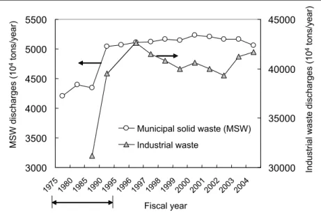
Figure 1 shows the changes in the amount of discharges of general waste (municipal solid waste:
MSW) and industrial waste resulting from the totality of these factors. Quantitatively, MSW has shown little change since 1995, but has increased approximately 20% since 1975. The amount of
Waste Recycling Technologies Required by a Sound Material-Cycle Society
KATSUYA KAWAMOTO
Affiliated Fellow
1
2
waste discharged per person (unit discharge) was around 1,000g/person-day before 1985, then increased to around 1,100g/person-day after 1990, and has declined since 2001. (Between 1985 and 2000, the increase in waste discharged was greater than the increase in population.) Here, it should be noted that unit discharge includes commercial and general household waste; the unit waste discharged purely by households is roughly 700-800g/
person-day. On the other hand, industrial waste increased substantially between 1985 and 1990,
but showed no large changes thereafter. Currently, approximately a half of annual discharge amount of 400 million tons is utilized after recycling.
As one index expressing the qualitative features of waste, Figure 2 shows the trend in the heating value of waste (MSW). Although the heating value of waste shows different values depending on the local government treating the waste, it increases consistently over time. This seems to be attributable to increased use of paper, plastic materials in packaging, and similar factors.
3000 3500 4000 4500 5000 5500
1975 1980
1985 1990
1995 1996
1997 1998
1999 2000
2001 2002
2003 2004 Fiscal year
MSW discharges (104tons/year)
30000 35000 40000 45000
Industrial waste discharges (104tons/year) Municipal solid waste (MSW)
Industrial waste
0 2000 4000 6000 8000 10000 12000
1950 1970 1990 2010
Fiscal year
Heating value(kJ/kg)
Osaka Tokyo (wards) Yokohama
Figure 1 : Change over time in amounts of municipal solid waste (MSW) and industrial waste (Data for 1975-1995 are for 5 year intervals).
Prepared by the STFC based on Reference [1]
Figure 2 : Change over time in heating value of waste (lower heating value) Prepared by the STFC based on Reference [2]
(2) Biomass
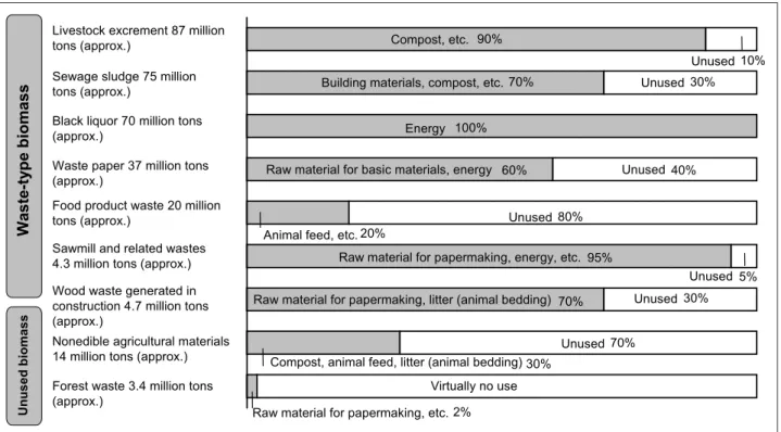
Biomass is classified into three types: 1 Waste- type biomass, 2 unused biomass, and 3 dedicated biomass crops (crops grown specifically for use as biomass). At present, biomass occurrence quantity and its utilization (carbon equivalent) are put at 298 million tons of waste-type biomass, which has a utilization rate of 72%, and 17.4 million tons of unused biomass with 22% utilization.[3]
Figure 3 shows rough values of the occurrence and utilization of various types of biomass.
Depending on the item, waste-type biomass may be either biomass in the form of industrial waste or biomass including both MSW and industrial waste. Of these, the items with direct potential for circulating use include food product waste, waste paper, and construction-generated waste wood, all of which have comparatively high unused ratios, and sawmill waste and other scrap wood, although the latter have relatively low unused ratios. Excluding livestock excrement, which has a high moisture content and tends to be produced in limited geographical areas, and sewage sludge, which also has a high moisture content (unused amount: 22.5 million tons), the amount of unused biomass for the four above-mentioned items exceeds 32.4 million tons. However, even though some kinds of waste-type biomass are
currently used, effective and useful applications have not necessarily been developed. The annual occurrence of waste-type biomass is estimated at approximately 327 million tons on a wet-weight base and 76 million tons on a dry base. By energy conversion, this corresponds to approximately 1,270PJ (petajoule: 1015 Joule).[4] By crude oil conversion, this is equivalent to approximately 32.8 million kiloliters, or about 5.6% of Japan’s total primary energy supply of 22,751PJ (FY 2005).
2-2 Transition of waste treatment technologies
(1) Transition of incineration treatment technologies
The direct purposes of incineration treatment are prevention of decay and stabilization by combustion treatment of waste at high temperature, and in combination with this, reduction of the weight and volume of the waste. Historically, however, the functions and roles widely required in incineration treatment have changed in response to the needs of the times, beginning with appropriate treatment for sanitation, followed by weight/
volume reduction and reduction of environment impacts, and later by recycling. In recent years, the dioxin problem brought about a particularly large change. In line with the movement toward a sound
Livestock excrement 87 million tons (approx.)
Sewage sludge 75 million tons (approx.)
Black liquor 70 million tons (approx.)
Waste paper 37 million tons (approx.)
Food product waste 20 million tons (approx.)
Sawmill and related wastes 4.3 million tons (approx.) Wood waste generated in construction 4.7 million tons (approx.)
Nonedible agricultural materials 14 million tons (approx.) Forest waste 3.4 million tons (approx.)
Compost, etc. 90%
Unused 10%
Building materials, compost, etc. 70% Unused 30%
Energy 100%
Raw material for basic materials, energy 60% Unused 40%
Animal feed, etc. 20% Unused 80%
Raw material for papermaking, energy, etc. 95%
Unused 5%
Raw material for papermaking, litter (animal bedding) 70% Unused 30%
Compost, animal feed, litter (animal bedding) 30%
Unused 70%
Virtually no use Raw material for papermaking, etc. 2%
Waste-type biomassUnusedbiomass
Figure 3 : Occurrence of biomass in Japan and breakdown of uses
Source: Reference [3]
material-cycle society, heightened expectations were placed on resource recycling through the introduction of new methods such as the gasification and melting furnace and other technologies.
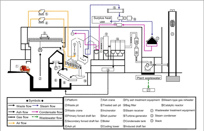
The number of waste incineration facilities has gradually decreased, and was 1,320 as of the end of FY 2005 (March 31, 2006). This represented a decrease of 25% from FY 1998. However, this number is extremely large in comparison with other countries. In Japan, large-scale fully- continuous facilities like that in the example in Figure 4 account for 40% of the total number of incineration facilities and more than 80% of treatment capacity. This type of large-scale facility includes a diverse range of equipment in addition to the actual incineration furnace, such as flue gas and wastewater treatment equipment, residue (ash) handling equipment, and power generating equipment, and the number of units of equipment is larger in these facilities. Technically, complete implementation of the 3Ts of Temperature, Time (residence time), and Turbulence (adequate mixing and stirring) is promoted by a variety of technical innovations, including improvement of the secondary combustion air injection method, advanced control using artificial intelligence, etc.
Incineration is extremely effective for the purpose of treating waste. However, it is also necessary to treat the incineration ash and fly ash generated in the incineration process. These substances are equivalent to approximately 10% and 3% of the incinerated waste, respectively. In case of landfill disposal of these substances, securing landfills and chemical treatment to prevent leaching of harmful substances contained in fly ash become problems.
Other issues include improving the recovery efficiency of metals, improving power generating efficiency, which is generally low at present, etc.
(2) Influence of the dioxin problem
The dioxins include the 4-8 chlorides of the polychlorinated dibenzoparadioxins (PCDDs), the 4-8 chlorides of the polychlorinated dibenzofurans (PCDFs), and among the polychlorinated biphenyl (PCBs), dioxin-like PCB, which has properties similar to the PCDDs and PCDFs.
These substances are environmental pollutants having the following features: In general, these substances are characterized by long-term persistence, high accumulation, and various types of toxicity. While they have diverse environmental effects in extremely low concentrations, reliable
㽾
㾅 㾄
㾃 㾁
㾂 㾀
Plant wastewater Surplus heat
use
㽿 㽽
㽷 㽹
㽳 㽻
㽼 㽺 㽶
㽵
㽴
㽸
Air flow
Wastewater flow Gas flow
Condensate flow Steam flow
䂹 䂹
Ash flow Waste flow
Symbols
㾃Induced draft fan 㽽Cooling tower
㽷Ash pit
Stack 㾂Condensate tank
㽼Boiler 㽶Secondary forced draft fan
Steam condenser 㾁Turbine-generator
㽻Ash pusher 㽵Primary forced draft fan
Wastewater treatment equipment 㾀Steam receiver
㽺Incinerator 㽴Waste crane
㾅Catalytic reactor 㽿Bag filter
㽹Treated ash pit 㽳Waste pit
㾄Steam-type gas reheater 㽾Fly ash treatment equipment
㽸Ash crane 㽲Platform
㽲
Figure 4 : Example of configuration of typical fully-continuous stoker-type incinerator
Source: Reference [5]
22 23
21
21 22 23
prediction is difficult. Because dioxins were discharged unintentionally from routine waste treatment processes, including also discharges accompanying the use of agricultural chemicals in the past, the pattern of penetration into the environment was different from that of conventional industrial pollution. The dioxins became an extremely large problem in Japan from around the mid-1990s. Subsequently, this had a direct effect on improvement of the element technologies of incineration treatment processes, including improvements in technologies, such as improvement of combustibility and higher efficiency in power generation, improvement in flue gas treatment technologies, such as changing dust collecting equipment to the bag filter, and others. This problem gave impetus to the implementation of regional waste treatment in an effort to reduce dioxins and recycle resources by regional collection and treatment of general waste in areas spanning several municipal units (cities, towns, and villages), and also led to a review of the conventional easy dependence on incineration and encouraged efforts to create a recycling society.
The following section will describe gasification and melting technology, which had a large influence.
(3) Melting treatment and the gasification and melting furnace
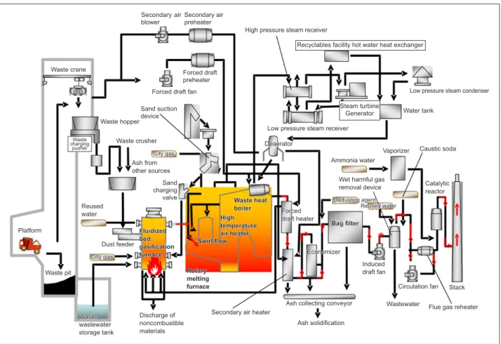
The aforementioned dioxin problem encouraged the development and introduction of gasification and melting furnaces (Figure 5) advanced. The features of this technology are as follows:
1 Dioxins can be reduced by high temperature combustion at 1,300-1,400°C in the melting process, and as a result, discharges can be minimized.
2 Because a reducing atmosphere is used in the gasification process, recovery and effective utilization of the metal content in the waste is possible.
3 Because the excess air ratio is low, the amount of flue gas is reduced. (The “excess air ratio”
is the ratio of the actual amount of air to that theoretically necessary for combustion). As a result, compact flue gas treatment equipment and other auxiliary equipment can be used, and power generating efficiency is improved.
Figure 5 : Example of typical gasification and melting plant (In case of fluidized bed gasification type)
Source: Reference [5]
Waste wastewater storage tank Waste charging
pusher
Ash from other sources
Deaerator City gas
Forced draft heater
Economizer Dedusting agent
Reused water
Catalytic reactor
High temperature air heater
Rotary melting furnace
Steam turbine Generator
Recyclables facility hot water heat exchanger
Fluidized bed gasification furnace
Swirl flow
Waste pit Platform
City gas Reused water
Dust feeder
Discharge of noncombustible materials
Sand charging valve Waste crusher Waste hopper
Sand suction device
Forced draft fan Forced draft preheater
Secondary air preheater Secondary air blower
Waste crane
Waste heat boiler
Secondary air heater
Ash collecting conveyor Ash solidification
Induced draft fan
Wastewater Flue gas reheater Circulation fan Stack
Caustic soda Vaporizer
Ammonia water Wet harmful gas removal device
Water tank Low pressure steam receiver
High pressure steam receiver
Bag filter
Low pressure steam condenser
4 If the heat contained in the waste is adequate, melting can be performed using the heat of the material being treated alone, thereby eliminating the need for supplementary energy inputs from external sources. In addition, the costs of construction and maintenance control are lower than with a combination of a general stoker furnace and ash melting furnace.
The process referred to as melting in gasification and melting is one that causes perfect combustion at high temperature. Gasification and reforming is a more advanced process, in which the composition of the gas is reformed by controlling the atmosphere, etc. under high temperature in a similar manner, producing a gas, such as carbon monoxide or hydrogen, which has use value as an energy source or feedstock for chemical synthesis processes. Gasification and reforming is a stage of technology that has been applied to waste incineration facilities in a small number of cases.
2-3 Transition to a sound material-cycle society and the flow of technology
(1) Formation of a sound material-cycle society Conventional waste treatment was performed so as to avoid environmental impacts, but was limited to a one-way type of treatment and disposal.
However, in recent years, there has been a common recognition in society that reducing CO2 emissions as a global warming countermeasure and recycling use of materials and energy are important issues.
This thinking has revolutionized the conventional concept of waste treatment. As a result, improvements have been made to actively promote recycling and recovery of energy and resources in incineration treatment itself, as described in section 2-2.
On the other hand, in countermeasures for harmful substances contained in waste, technical progress has been achieved from the viewpoint of reducing the spread and the risks of chemical substance extending to the global scale, for example, in countermeasures based on the Stockholm Convention on Persistent Organic Pollutants (POPs), which took effect in May 2004.
The treatment of PCB is a typical example of this.
Similarly, the development and introduction of treatment/disposal technologies is also progressing.
Examples include technologies for the mercury contained in batteries, fluorescent tubes, and other
products, asbestos contained in many products, beginning with building materials, and infectious waste, among others.
From the viewpoint of contributing to the 3Rs, there are technologies which aim at reducing waste by improving efficiency in the use of raw materials, etc. and extending the life of products, and technologies which aim at reuse, as seen in parts for copying machines. Where recycling is concerned, the development of design techniques which improve ease of disassembly during recycling and improve the potential for recycling of resources may be mentioned.
As a technology for recycling, in other words, recovery and use, various technologies have been developed for waste PET bottles and waste plastics, which are classified as container and packaging waste. The technologies that have been developed include material recycling, in which the waste plastic is processed again into molded products,
“bottle-to-bottle” recycling, in which waste PET bottles are reused as raw material for new PET bottles, a method in which waste plastic is used as a reducing agent in the blast furnace, and a method in which waste plastic is thermally decomposed in the coke oven, producing oil and coke oven gas for use as industrial raw materials.[1] Technologies related to these items are described in detail in the following Chapter 3. However, in recent years, the amount of waste exported to China and other countries has increased, as represented by PET bottles. Under these circumstances, there is concern not only that this trend will make it impossible to make full use of the excellent recycling technologies which Japan possesses, but also that the sound material-cycle society as a whole will suffer.
Three general indexes may be mentioned in connection with the aims in constructing sound material-cycle society systems. These are resource productivity (= GDP/Inputs of natural resources, etc.), the circulating use ratio (= Circulating use / (Circulating use + Inputs of natural resources, etc.)), and final disposal (amount of final disposal in landfills). The targets up to the FY 2010 are to increase resource productivity to approximately
\390,000/ton, improve the circulating use ratio to approximately 14%, and reduced landfill disposal to approximately 28 million tons.[1] The following
may be mentioned as conditions required in waste recycling technologies for the formation of a sound material-cycle society: The technology in question must 1 reliably accomplish appropriate treatment of waste (effectiveness and practicality of treatment), 2 be capable of efficiently producing an energy source or material as a recycled product (effectiveness and practicality of recycling process), 3 have appropriate cost and energy consumption for recycling (economy), 4 be capable of minimizing environmental loads (low environmental load), and 5 produce a recycled product that can be effectively utilized (utility of the recycled product). Although concrete indexing should be carried out prudently, it can be thought that an easily understood evaluation of technologies will be required.
(2) Technologies using biomass
In Japan, the Biomass Japan Comprehensive Strategy was adopted by a resolution of the Cabinet in December 2002. Internationally, the Kyoto Protocol has come into effect, making implementation of effective global warming countermeasures extremely urgent, while the rapidly rising price of crude oil has led to a deeper recognition of the necessity of reducing dependence on fossil resources. These various factors have heightened interest in biomass energy.
In March 2006, the Biomass Japan Strategy was revised.[6]
In the revised Strategy, concrete targets for the realization of “Biomass Japan” are arranged from the technical, regional, and national viewpoints.
From the technical viewpoint, the revised strategy sets targets in connection with conversion efficiency or raw material price for direct combustion and gasification plants as technologies for converting low-moisture biomass to energy, for methane fermentation and other technologies as technologies for converting high-moisture biomass to energy, and for the production of biomass- derived plastics as technologies for converting biomass to products.
Based on this, the Ministry of the Environment has made technologies in connection with bioethanol and biodiesel an object of priority technical development. The Strategic Technology Roadmap 2007 (STR) published by the Ministry of Economy, Trade and Industry (METI) includes a roadmap for the 3Rs field. Biomass-related technologies are shown under “Other main 3R technologies” other than metal resource 3Rs, as shown in Figure 6.
According to Figure 6, the main development targets for biomass utilization are fermentation t e c h n o l o g y a p p l y i n g t h e f u n c t i o n o f microorganisms, fuel conversion technology based on thermochemical principles, and higher efficiency in existing power generation. In biomass recycling technologies, the key issues are considered to be improvement of methane and ethanol fermentation technologies, development of hydrogen fermentation technology, high efficiency gasification, conversion to liquid fuels, and the like. In the following chapter, these items will be examined concretely.
Development of lignophenol applications (wood) Other
Household energy conversion (food) Material/energy co-production
technologies -
Gasification technology (wood/sludge) 㽲㽳㽴 High efficiency BDF production (food) 㽴
Fuel production technologies
㽳 Hydrogen fermentation (food/sludge) 㽴
Methane fermentation (food/livestock/sludge) Ethanol fermentation (woody biomass) 㽲㽳㽴 Fermentation
technologies
Coal mixed-firing power generation 㽲㽳㽴 Power generating
technologies (wood)
2030 2025
2020 2015
2010 2009 2008 2007
~2006
Long-term Medium-term
Short-term
-
㽲㽳㽴 㽴 Composting (food/livestock) 㽳
㽴 㽲㽳㽴 㽲㽳㽴 High efficiency compact generator
2030 2025
2020 2015
2010 2009 2008 2007
~2006 themeMain Subcategory
Category
High efficiency power generation Coal mixed-firing power generation
High efficiency ethanol fermentation technology High efficiency methane fermentation technology
Hydrogen fermentation technology Composting technology (high quality on large scale)
BDF production
Gasification & reforming + Fuel production (GTL hydrogen production) technology High efficiency gasification &
reforming + Fuel production (GTL hydrogen production) CO2-free hydrogen and carbon co-production Fuel production and energy (electric power, heat) co-production
Material/energy recycling chemical production process technology (gasification) Household energy conversion technology (conversion to methane, hydrogen, etc.) Lignophenol application technologies
Biomass(wood-,foodproduct-, livestock-,sewage-derivedbiomass)
Figure 6 : Strategic Roadmap of individual biogas technologies prepared by METI
Source: Reference [7]
3 Waste recycling technologies required by a sound material- cycle society
3-1 Outline and comparison of technologies Table 1 presents an outline and comparison of the waste recycling technologies which provide the conditions desired in a recycling based society and are considering promising for the future. The respective technologies will be described in the following sections.
3-2 Technologies utilizing biofunctions
(1) Biogasification
Food waste (garbage) and food product waste have become one focus as resources with comparatively low circulating use ratios. From the viewpoint of biomass-type circulating resources, food waste, wood chips, sludge, livestock excrement, etc. account for approximately half of the amount of waste generated. Because these substances have high contents of moisture and organic matter, their circulating use ratio is 16%, and the reduction ratio of weight by incineration and dewatering is limited to 53%. At present, many examples of circulating use are in the field of agriculture, where these substances are used as fertilizers and animal feed. However, there are
questions about these methods of use whether they are optimal.
Given these circumstances, methods of biogasification of food waste and waste paper by methane fermentation and recovery of methane gas are under study. Methane fermentation of thick organic waste, sewage sludge slurry, and similar wastes is a technology with a long history of use and does not involve any technical novelty. However, in application to solid wastes with relatively low moisture contents, various improvements will be necessary in the future.
In methane fermentation processes, liquid and solid residues are produced after the gas is recovered. For this reason, appropriate treatment/
disposal of these substance considering the environment is desirable. The liquid residue is a highly concentrated waste liquid after fermentation, which is called digestion sludge. Because the reduction ratio of sewage sludge and similar wastes has an upper limit of 40-50% with the current technology, it is necessary to increase the decomposition ratio of the organic component and improve energy efficiency.[8] On the other hand, where the solid residue is concerned, reduction by incineration with other combustible wastes is one direction for improving efficiency. Figure 7 shows an example of an analysis of the energy recovery effect when biogasification and incineration
Table 1 : Comparison of waste recycling technologies
Prepared by the STFC.
Evaluation item Technologies using microorganisms Gasification technologies High temperature/high pressure fluid technologies
Main object
substance · Wet biomass, mainly foods:
20 million tons/year (approx.)
· Dry biomass, mainly wood, paper, etc.: 16 million tons/year (approx.) (general waste: 50 million tons)
· Food, animal residue, and other wet-type wastes. Application to wood-derived biomass is also studied. Applicability to toxic wastes is a feature.
Recycled product · Biogas, mainly methane
· Hydrogen
· Biomass plastics
· Hydrogen, CO
· Methanol
· Liquid fuels
· Intermediates such as raw material for methane fermentation, etc., chemicals.
Technical principle and evaluation of system
· Hydrogen fermentation, methane fermentation, ethanol fermentation, lactic acid fermentation by biological systems
· Systemization of gasification and incineration
· Pyrolysis, gas reforming (from high temperature to low temperature)
· Systemization using gas engine generator, fuel cell, etc.
·Systemization with ethanol production and liquid fuel production
· High speed, high efficiency reaction with special fluid.
· Systemization with methane fermentation, gas reforming, etc.
Cost
· Same as conventional technology;
however, advantageous if effective utilization of recovered energy is possible.
· Low temperature processes are advantageous because energy requirements are reduced.
· Possible to reduce total cost by using pyrolysis char as heat source.
· Use of subcritical water is more advantageous than supercritical because required heat and energy for pressurization are lower.
Outlook for practical application and problems
· Some facilities. Because sorting is not easy, expansion to MSW treatment facilities is a problem.
· Reduction of price of plastic products
· High temperature facilities exist.
However, low temperature processes and systemization with liquid fuel are future developments.
· Some facilities. Problems include resistance of materials to high pressure, corrosive environment.
are combined. Because power generation using the heat of both the biogas and incineration can be performed using advanced, high efficiency equipment in this method, energy recovery can be performed effectively by a system simply combining power generation with incineration.
Examples of introduction can already been seen in private-sector waste treatment facilities. In an example in which the energy balance was calculated for the case of incineration of 100% of waste and a case in which part of the food waste was sorted and used in methane fermentation under certain conditions (assuming that the biogas is used for power generation with a gas engine), it was estimated that the amount of generated power increases by approximately 16% in the case with partial gasification.
However, where incineration is concerned, it goes without saying that adequate countermeasures for air pollutants, beginning with dioxins, must be adopted.
(2) Hydrogen fermentation and ethanol fermentation
In the Strategic Technology Roadmap in Figure
6, development of hydrogen fermentation in fermentation technologies is predicted as a mid- to long-term technology. This appears to be based on the assumption of an emerging hydrogen society.
In processes in which organic compounds are subjected to methane fermentation under anaerobic conditions, hydrogen is generated in the acid fermentation stage. For example, in case glucose is used as the fermentation substrate, C6H12O6 + 2H2O
→ 2CH3COOH + 4H2 + 2CO2. Representative bacteria which form hydrogen under anaerobic conditions include the Clostridium species, Enterrobacter species, and others.
Because hydrogen fermentation is normally a transition process, it is unstable. To obtain a stable recovery rate, it is necessary to provide environmental conditions for culture within the optimum range. Thus, the key to development aiming at improvement and practical application of hydrogen fermentation technologies is considered to be one of the following:
1 Achievement of long-term sustained hydrogen recovery using mixed microorganisms by optimizing its environmental conditions.
2 Isolation of a microorganism with a high
Biogas + incineration Energy efficiency* = 25%
Waste Garbage Methane
fermentation Biogas Gas engine
84MWh Power
466MWh Total generated
power 382MWh
Power Incineration
Residue
Combustible material Residue
Incineration Energy efficiency* = 21.7%
Waste Incineration 403MWh
Total generated power
** Energy efficiency = (Generated power x 3,600) / (Heating value of waste) 1,000ton
6.7MJ/kg Moisture 50%
360ton 1.9MJ/kg Moisture 80%
49ton 3.3MJ/kg
1,000ton 6.7MJ/kg Moisture 50%
640ton
9.4MJ/kg 689ton
9.0MJ/kg Moisture 36%
Figure 7 : Example of trial calculation of energy recovery effect by methane fermentation process Source: Reference [9]
hydrogen fermentation capacity and effective utilization of its capacity.
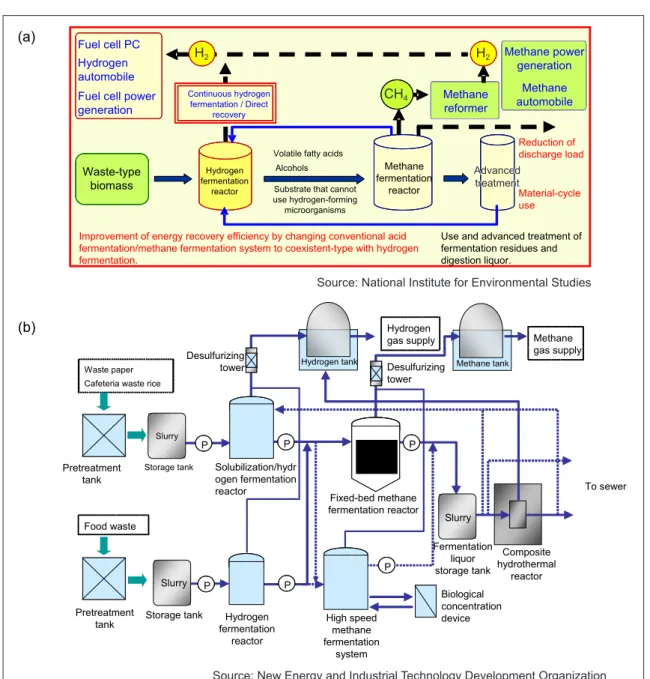
Accordingly, research and development are being carried out in connection with fermentation technologies which promote hydrogen formation from mixed microorganisms with high efficiency and the related recovery processes, or the search for microorganisms with a high hydrogen-forming capacity. Examples of main large-scale research projects[10] include “Technical development of 2-stage fermentation technology for organic wastes centering on high efficiency hydrogen/
methane fermentation” (FY 2001-2005), which was carried out by private-sector companies and the National Institute of Advanced Industrial Science and Technology (AIST), under the
leadership of Japan’s New Energy and Industrial Technology Development Organization (NEDO), the “Development of Kuzumaki Town advanced use cogeneration system,” carried out under the leadership of Tohoku University, and the technical development project “Development of hydrogen production technology using bioresources/waste, etc.” (FY 2003-2007) of the National Institute for Environmental Studies (NIES). In addition to these, there are also numerous examples of research on hydrogen-forming bacteria by other research institutes and private companies.[11,12]
Figure 8 (a) and (b) show the development concept of the hydrogen/methane 2-stage fermentation process developed by NIES and the configuration of a system of 1/10-1/100 scale of actual size by (a) Fuel cell PC
Hydrogen automobile Fuel cell power
generation Methane
reformer
Waste-type biomass
Hydrogen fermentation
reactor
Volatile fatty acids Alcohols
Use and advanced treatment of fermentation residues and digestion liquor.
Substrate that cannot use hydrogen-forming
microorganisms
Improvement of energy recovery efficiency by changing conventional acid fermentation/methane fermentation system to coexistent-type with hydrogen fermentation.
Reduction of discharge load
Material-cycle use Continuous hydrogen
fermentation / Direct recovery
Methane power generation
Methane automobile
Methane fermentation
reactor
Figure 8 : Examples of the development concept of hydrogen/methane 2-stage fermentation process (a) Development concept proposed by NIES (b) System configuration proposed by NEDO
High speed methane fermentation
system
(b)
Slurry
Slurry Waste paper
Cafeteria waste rice
Hydrogen
gas supply Methane
gas supply
Food waste
To sewer
Biological concentration device
Composite hydrothermal
reactor Fermentation
liquor storage tank
Hydrogen fermentation
reactor Storage tank
Pretreatment tank Pretreatment
tank Storage tank Solubilization/hydr ogen fermentation reactor
P Desulfurizing
tower Hydrogen tank Desulfurizing tower
Methane tank
Fixed-bed methane fermentation reactor
P P
P
P P
Slurry
(a) Fuel cell PC Hydrogen automobile Fuel cell power
generation Methane
reformer
Waste-type biomass
Hydrogen fermentation
reactor
Volatile fatty acids Alcohols
Use and advanced treatment of fermentation residues and digestion liquor.
Substrate that cannot use hydrogen-forming
microorganisms
Improvement of energy recovery efficiency by changing conventional acid fermentation/methane fermentation system to coexistent-type with hydrogen fermentation.
Reduction of discharge load
Material-cycle use Continuous hydrogen
fermentation / Direct recovery
Methane power generation
Methane automobile
Methane fermentation
reactor
Source: National Institute for Environmental Studies
Source: New Energy and Industrial Technology Development Organization Source: National Institute for Environmental Studies
Source: New Energy and Industrial Technology Development Organization H2
H2
CH4
Advanced treatment
NEDO. As features of the technology developed by NIES, the aims include recovery of hydrogen and methane, and simultaneously, removal of the eutrophication salts such as nitrogen and phosphorus. Figure 9 shows the results of a continuous hydrogen recovery test conducted over a 150-day period using food waste from a cafeteria as the raw material. Hydrogen gas with a concentration of approximately 50vol% was obtained continuously. This test also clarified the fact that maintaining a substantially constant pH in the system by returning the digestion sludge after methane fermentation to the hydrogen fermentation reactor is an important condition.
Where ethanol production from biogas is concerned, because the target for introduction of so-called eco-fuels has been set at 500,000kl by crude oil conversion (equivalent to approximately 0.6% of all fuels used in transportation in Japan), active technical study of bioethanol, biodiesel fuel (BDF), liquefied biomass fuel (biomass-to-liquid:
BTL), and other fuels is underway. Japan is also targeting production from waste-type biomass.
An ethanol production plant using waste wood from the building industry as the raw material began operation at a scale of 1,400kl/year in Osaka Prefecture in January 2007. In this process,
waste wood which has been collected from the neighboring area is crushed, followed by hydrolytic degradation by dilute sulfuric acid under pressure.
As a particular feature, the process utilizes a bacterium which enables use of hemicellulose together with cellulose, which is a sugar (hemicellulose is a type of short-chain sugar).[14] In Okayama Prefecture, a pilot test is being conducted on ethanol fermentation using a special yeast with unused waste wood from sawmills, etc. as the raw material, production of anhydrous ethanol using a separation membrane, and E3, which is a mixed fuel containing 3vol% of ethanol. Ethanol production is 250kg/day.[10]
(3) Biomass plastic
The material that has attracted the highest expectations as a biomass plastic is poly-L-lactic acid (PLLA), which is produced by fermenting multiple vegetable-derived sugars. Because PLLA is more easily decomposed by processes such as hydrolytic degradation than petroleum-derived plastics, conversion to L-lactic acid and similar raw material substances is comparatively easy.
PLLA is not simply only a plastic which is easily biodegradable in the environment, but can also be considered a recyclable plastic material,[15] and is
0 20 40 60 80 100
0 20 40 60 80 100 120 140 160
ᤨ㑆
(d)
⚵ ᚑ (% )
0 5 10 15 20
0 20 40 60 80 100 120 140 160
↢ ᚑ ㊂ (L 䊶 d
-1䊶 L
-1)
Formation rateTime
Composition
Figure 9 : Generated gas composition and hydrogen formation rate (velocity) in long-term test of hydrogen fermentation reactor (●: H2, ×:CH4, ○:CO2 ) 13)
Source: Reference [13]
100
0 20 40 60 80 100
0 20 40 60 80 100 120 140 160
ᤨ㑆
(d)
⚵ ᚑ (% )
0 5 10 15 20
0 20 40 60 80 100 120 140 160
↢ ᚑ ㊂ (L 䊶 d
-1䊶 L
-1)
Formation rateTime
Composition 0
20 40 60 80 100
0 20 40 60 80 100 120 140 160
ᤨ㑆
(d)
⚵ ᚑ (% )
0 5 10 15 20
0 20 40 60 80 100 120 140 160
↢ ᚑ ㊂ (L 䊶 d
-1䊶 L
-1)
Formation rateTime
Composition(L・d-1 ・L-1 )(%)
therefore an attractive object for material recycling.
One important issue for producing PLLA from biomass is reduction of the cost of the refining process, for example, by a distillation process which produces high purity lactic acid from the lactic acid fermentation broth.[16] In order to obtain products which are competitive with low-cost petroleum-derived plastic products, the above- mentioned recycling from PLLA is one useful method for development of a low-cost production process.
3-3 Improvement of gasification technology Effective utilization of waste was already a priority in Japan in the 1970s. The former Agency of Industrial Science and Technology, Ministry of International Trade and Industry (MITI; the corresponding organizations are the new AIST, which was mentioned previously, and the Ministry of Economy, Trade and Industry, METI) carried out a comprehensive research and development project called “Stardust 80” in connection with
“Resource recycling and use technology systems”
from FY 1973 to FY 1982. As part of this project, a pilot plant with a municipal waste treatment capacity of 100 tons/day was constructed in Yokohama. The plant comprised a total of six subsystems, including pretreatment for sorting and
crushing municipal waste, high speed composting for garbage, pulp recycling from waste paper, pyrolysis and gasification for conversion of waste paper and waste plastic to oil and gas, and others.
The targets were to recycle municipal solid wastes with a miscellaneous composition as material resources or energy resources, and to achieve high compatibility with social systems by minimizing secondary pollution, etc. Nevertheless, a number of problems remained to be solved with the gasification technology, including the fact that both the equipment cost and running cost were extremely high, treatment of acidic tarry substances was not possible, etc.[17] As a result, it would be difficult to call the project a success.
However, with progressive introduction of gasification and melting technologies following this project, as described previously, substantial improvements were made in the gasification technology, melting technology, and other elements. Moreover, because expectations were also placed on resource recycling and hydrogen energy, gasification technology became the focus of renewed interest. For example, there was an case in which a system for synthesizing hydrogen using waste plastics as the raw material (Ebara Ube Process: EUP) was applied commercially to the production of hydrogen for use in ammonia
Gas refining
Point 3: Establishment of method of
application of catalyst to increase hydrogen recovery capacity and reduce byproducts Pyrolysis gas
H
2 CO2 CO Point 1: Evaluation ofapplicability to various types of waste
Municipal waste Waste
plastics
Steam Biomass
Reformed gas
Fuel cells, etc.
H2S H2CO CH4
O
2Point 2: Establishment of optimum gasification conditions at comparatively low temperature
Catalyst, etc.
Figure 10 : Development concept of gasification and reforming system
Source: Reference [10]
synthesis.[18] The technology in this example is a pressurized 2-stage process, comprising a low temperature fluidized bed-type gasification furnace (600-800°C) directly connected to a high temperature (1300-1500°C) swirl flow combustion chamber-type gasification and melting furnace. In addition, there are also a small number of examples of application to gasification and reforming-type MSW treatment.[19]
Although these technologies have attracted attention, it is difficult to say that application to biomass and MSW has made wide progress. As the reason for this, because a high temperature melting process is necessary, the process is subject to various restrictions, including the quantity of heat in the raw materials, cost performance, plant operability, and so on. Therefore, in order to promote utilization of biomass and expand the supply sources of hydrogen gas, technical development is underway with the aim of realizing a lower temperature process than with the developed technology, centering on the reforming process. As illustrated in Figure 10, technical development is being carried out based on the concept of compensating for the problem of reduced efficiency due to low temperature operation by applying a catalyst. A variety of issues are being studied in this development project, including the temperature when hydrogen is the main substance recovered, the steam and oxygen injection volume,
the composition of the catalyst and amount used, the method of catalyst regeneration, and the gas refining effect, among others, with the objective of discovering the optimum applicability to waste or biomass.
For example, Figure 11 shows the results when a catalyst containing 20wt% of nickel as the active ingredient and somewhat over 10wt% of calcium oxide is applied, in comparison with the results with no catalyst in operation at different temperatures. In an experiment with waste wood, when using this catalyst, a gas with the same or higher concentration of hydrogen gas as in a process at 950°C with no catalyst could be obtained at 750°C.[10]
Similarly, as a project in connection with a biomass utilization technology in which gasification is an element technology, the Ministry of Education, Culture, Sports, Science and Technology (MEXT) Leading Project “Composite treatment and recycling project for municipal solid waste, industrial waste, and biomass” was carried out during the period FY 2003-2007.[20]
Here, development of a high efficiency process technology for recovery of energy and resources from waste was carried out as one sub-theme, and included the development of a high efficiency gasification conversion technology, development of a high efficiency gasification system technology, development of a high efficiency power generating 57.08
54.7
42.11
0 10 20 30 40 50 60
Gas Composition(vol.%)
G-90LDP (S/C=1.67, 1023K)
Non-Catalytic 1 (S/C=1.91, 1223K)
Non-catalytic 2 (S/C=3.02, 1023K)
H2 CH4
CO CO2
CnHm 57.08
54.7
42.11
0 10 20 30 40 50 60
Gas Composition(vol.%)
G-90LDP (S/C=1.67, 1023K)
Non-Catalytic 1 (S/C=1.91, 1223K)
Non-catalytic 2 (S/C=3.02, 1023K)
H2 CH4
CO CO2
CnHm 57.08
54.7
42.11
0 10 20 30 40 50 60
Gas Composition(vol.%)
G-90LDP (S/C=1.67, 1023K)
Non-Catalytic 1 (S/C=1.91, 1223K)
Non-catalytic 2 (S/C=3.02, 1023K)
H2 CH4
CO CO2
CnHm 57.08
54.7
42.11
0 10 20 30 40 50 60
Gas Composition(vol.%)
G-90LDP (S/C=1.67, 1023K)
Non-Catalytic 1 (S/C=1.91, 1223K)
Non-catalytic 2 (S/C=3.02, 1023K)
H2 CH4
CO CO2
CnHm
(1023 K)
⸅ᇦ䈅䉍 ⸅ᇦ䈭䈚(1223 K)
⸅ᇦ䈭䈚(1023 K)
䉧 䉴 ⚵ ᚑ (v ol % )Gas composition (vol%)
With catalyst No catalyst No catalyst
Figure 11 : Difference in formed gas composition depending on application of catalyst
(Numbers in parentheses on the x-axis show temperature. CnHm means hydrocarbon species.) Source: Reference [10]
CO2
CH4
H2
technology, and development of a hydrogenation and liquid fuel synthesis technology.
In treatment technologies that use heat, environmental consideration in connection with the flue gas discharged out of the system is particularly important. Pyrolysis gasification technologies do not release flue gas directly into the open environment. However, in fuel cells, gas engine generators, and other technologies which are the use stage of the product gas, it is necessary to avoid environmental impacts related to operation, for example, due to tar and the like.
Accordingly, the objects that must be considered is different from the case of incineration and other technologies which are premised on direct release into the general environment. The problems which arise here include sulfur compounds (hydrogen sulfide, etc.) which can easily damage the catalysts, polycyclic aromatic compounds, which form tar, hydrocarbons, which may cause carbon deposition, etc. Basically, it is possible to cope with refining of this kind of flue gas using conventional technologies, but from the viewpoint of optimization of the temperature conditions and the economy of the system as a whole, the optimum values will differ in each case.
3-4 Technologies applying high temperature/
high pressure fluids
As high temperature, high pressure fluids, supercritical water, subcritical water, and
supercritical CO2 are extremely distinctive fluids which make it possible to change properties from high polarity to nonpolarity, depending on the temperature and pressure conditions. A fluid in a state in which the temperature is approximately 370°C and pressure is 22MPa or higher is generally called a supercritical water. Because water in this condition is in a mixed state consisting of a liquid (reaction solvent) and gas, its strong oxidizing power can be utilized effectively, enabling application to the decomposition of hard-to- decompose substance such as organic chlorides, etc. and the detoxification of harmful chemical substances. On the other hand, subcritical water is a more moderate state than supercritical water, as its temperature/pressure are not as high as supercritical conditions. Because its ion product is larger than that of ordinary water and its reactivity is high, it can be used in reaction fields where the hydrolytic degradation reaction proceeds rapidly. Conventionally, supercritical fluids with high reactivity were the main type used in decomposition treatment of substances. However, technical studies are examining the possibility of recovering various substance by using subcritical water in this reaction field. Possible applications include reducing plastics to monomers and recovering amino acids from protein-type waste.
For example, a recycling process in which stepwise subcritical water treatment is applied to waste fish flesh has been proposed. It is possible
Shortening of fermentation treatment time Compact design of fermentation reactors and wastewater treatment equipment
Reduction of amount of sludge generated, etc.
Food product waste
Subcritical water reactor
Separation/recovery
Methane fermentation reactor
Wastewater treatment equipment
Valuable materials
Digestion rate:
90% (approx.) Gas holder
Biogas
Depolymerization
Figure 12 : Example of recycling applying subcritical process
Source: Reference [23]
to separate and recover pyroglutamic acid, cystine, alanine, glycine, and leucine by first refining, separating, and recovering lactic acid, phosphoric acid, and histidine in a reaction for approximately 5min under conditions of 200°C and 1.6MPa, followed by a reaction for approximately 30min at 270°C under 5.5MPa.[21] Subcritical water can be used in the recovery of tolylene diisocyanate (TDI), which is a raw material for polyurethane, in a process in which TDI is produced based on toluenediamine recovered from the residue.
Subcritical water can also be applied to a process in which sugars are obtained from cellulose with high efficiency by applying subcritical water to woody biomass and adjusting the decomposition rate, and then proceeding to ethanol fermentation.[22]
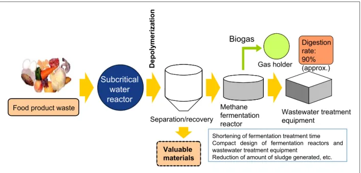
Possible applications include depolymerization as a pretreatment process, extraction of useful components, and gasification/oilification, etc.
Figure 12 shows the concept of a combined system which depolymerizes high molecular weight organic compounds in food product waste utilizing subcritical water and then supplies the product to a methane fermentation process. In this example, a subcritical water process is applied, enabling rapid hydrolytic degradation, which requires time in methane fermentation, while also producing a composition which is suitable qualitatively for
methane fermentation.
The fact that these are high temperature/high pressure fluids also gives rise to various technical issues, including the durability of the reaction equipment, separation and refinement of the recovered substances, increased costs, and others.
However, when the waste is in a dried condition, it is possible to recover bioactive components by supercritical CO2 extraction. With wastes with a high moisture content, recovery of water soluble bioactive components and the like is possible by solubilizing the waste using subcritical water, and development to methane fermentation is possible after depolymerization. Thus, if the proper treatment is selected based on the moisture content of the waste, properties of the contents, etc., recycling of wastes can be maximized. Figure 13 shows the flow of recycling and use when this concept is applied to bean curd waste discharged from the tofu manufacturing process.
Issues and Recommendations
4-1 Issues for waste recycling technology as a total technology
The author would like to point out the following as technical issues for the recycling of wastes.
First, some technologies which are applied to waste
Extraction using supercritical CO2
䍃Vitamin E 䍃Palmitic acid 䍃Oleic acid 䍃Linoleic acid 䍃Linolenic acid
Bean curd refuse (dry) 䍃Protein 䊶Fats 䊶Hydrocarbons 䍃Ash
䊶Lactic acid 䊶Methane 䊶Bioactive substances
䊶Amino acids, organic acids 䊶Phosphorus
Aerobic treatment Dissolution using
subcritical water Sludge
Solution Sludge
Digestion liquor Sludge 䊶Methane fermentation
䊶Lactic acid fermentation Tofu processing
Bean curd refuse (wet)
Drying
䊶Compost 䊶Animal feed 䊶Incineration
Wastewater
Raw material for biomass plastics Fuel for drying process
Current Future proposal
䊶Food products 䊶Animal feed 䊶Incineration
Problems
䊶Surpluses of both compost and animal feed
䊶Compost is unstable
䊶Causes reduction in incinerator temperature
Figure 13 : Current status of treatment of bean curd lees and proposal for recycling system
Prepared by the STFC based on Reference [21]


![Figure 7 : Example of trial calculation of energy recovery effect by methane fermentation process Source: Reference [9]](https://thumb-ap.123doks.com/thumbv2/123deta/6927143.2265947/9.892.104.787.80.560/figure-example-calculation-recovery-methane-fermentation-process-reference.webp)