Simultaneous Allocation and Binding Considering Multiplexers in High-Level Synthesis
6
0
0
全文
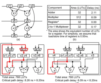
(2) Vol.2011-SLDM-148 No.15 2011/1/17 IPSJ SIG Technical Report. v1. v3. v2. Component Adder. +1. X1 v4. v5. +3. +2 v6. sider MUXs only by the total number of interconnections and do not care where the MUXs would be inserted, they may significantly worsen performance of circuits in large designs due to the MUXs inserted on a critical path. This example shows the importance of simultaneous allocation and binding optimization and that of path delay consideration for synthesizing efficient circuits in terms of both area and performance.. Area (LUTs) Delay (ns) 32. 2.11. Multiplier. 512. 8.09. Register*. 32. 0.00. 2-to-1 Multiplexer. 32. 0.17. * The area shows the equivalent number of LUTs for a register. For simplicity, we assume that load/store time of registers is 0.00ns. (b). v7 (a). MUX. MUX. MUX. v1,v5,v7. v2,v4. v3,v6. x1. +1,+3. +2. Total area: 768 LUTs Critical path delay: 8.26 ns > 8.20ns (c). MUX. v4. x1. v1,v5,v7. +2. 3. Simultaneous Allocation and Binding This section presents our HLS technique which simultaneously optimizes allocation and binding of FUs and registers considering MUXs under a clock constraint. 3.1 Preliminaries and Definitions We propose a novel simultaneous allocation and binding method for minimizing the total area of FUs, registers, and MUXs under a clock constraint. This method is formulated as an ILP problem. Also, an effective ILP-based heuristic for non-small designs is presented. To the best of our knowledge, this is the first work which simultaneously optimizes not only FU/register binding but also FU/register allocation under the clock constraint by considering the influences of MUXs on both the area and performance of a circuit. The input to our method is a scheduled DFG, the maximum number of FUs and registers (i.e., FUs and registers for unsharing), and a constraint on the clock period given by a designer. A DFG is an acyclic directed graph, where nodes and edges represent operations and data dependencies, respectively. Data which are generated in a clock cycle and used in another clock cycle are called values and need to be stored in registers. In the remainder of this paper, operations and values are collectively called tasks, and FUs and registers are collectively called agents. Resources represent agents and MUXs. We assume that the type of agents which can execute tasks is unique. Tasks can share the same agent if there is no type conflict in assigning the tasks to the agent (e.g., values to registers and additions to adders) and their lifetime does not overlap each other. The lifetime of a value is defined as the period in clock cycle from the generation to the last use of the value. Similarly, the lifetime of an operation is defined as the period in clock cycle from the initiation to the termination of the operation. For a single-cycle operation, its initiation and termination are in the same clock cycle. The goal of our work is to simultaneously determine allocation (i.e., how many instances should be used for each type of agents) and binding (i.e., which tasks. MUX. v2,v6. v3. +1,+3. Total area: 768 LUTs Critical path delay: 8.09 ns < 8.20ns (d). Fig. 1 Motivating example: (a)An input scheduled DFG, (b)Hardware resources, (c)An optimal solution obtained by 1), and (d)An optimal solution obtained by our method.. adders, one multiplier, and three registers are given as the allocation. Fig. 1(c) shows an optimal circuit obtained by 1). The circuit has three MUXs, each of which is inserted before each register. As a result, it has one multiplier (×1) and one MUX on its critical path (depicted as a bold line in the figure). The area and clock period of the circuit are 768 LUTs and 8.26ns, respectively. In contrast, our method (explained in Sect. 3) simultaneously optimizes allocation and binding for minimizing the total area including MUXs while meeting a clock constraint by considering where the MUXs would be inserted. Fig. 1(d) describes a circuit obtained by our method when the clock constraint is set as 8.20ns. Since the circuit gains 32 LUTs by increasing one register but loses 32 LUTs by decreasing one MUX, the total area eventually becomes the same as the one in Fig. 1(c). Futhermore, the circuit in Fig. 1(d) meets the clock constraint, while the circuit in Fig. 1(c) does not. In this example, our work achieves the better performance with no area overhead than 1). As shown here, our work minimizes the total area including MUXs under a clock constraint. Circuits such as the one in Fig. 1(d) cannot be obtained by existing works which conduct binding under given allocation. Moreover, since most existing works con-. 2. c 2011 Information Processing Society of Japan °.
(3) Vol.2011-SLDM-148 No.15 2011/1/17 IPSJ SIG Technical Report Table 1 Definition of notations.. should share agents) so that the total resource area (i.e., the total area of FUs, registers, and MUXs) is minimized while meeting the clock constraint. Considering the area and delay of the controller and routing logic is our future work. 3.2 ILP Formulation We formulated our simultaneous allocation and binding method as an ILP problem below. Notations in the following formulas are defined in Table 1. Note that notations starting with a capital letter are all constants and only those in a small letter are variables. Operation chaining and multi-cycle/pipelined operations can be handled by the following formulas without extension?1 . Assignment: Each task X should be assigned to one and only one agent; xi,j = 1 ∀i ∈ T asks. T asks Agents Resources T askT ypei AgentT ypej Assignablei,j Csteps Activei,t xi,j Conf licti,i0 Dataf lowi,i0 ,m wj,j 0 ,m. (1). InOperandi. j∈Agents. Also, an agent can perform at most one task in each control step; (xi,j + xi0 ,j ) × Conf licti,i0 ≤ 1 ∀i, i0 ∈ T asks, i 6= i0 , ∀j ∈ Agents. InP ortsj. (2). nj,m P ath T askP athi,p ConstDelay dp M U Xl Delayk Areak yj. 0 0 where Conf Plicti,i = 1 if both of tasks i and i are active in at least one control step (i.e., t∈Csteps Activei,t × Activei0 ,t ≥ 1), otherwise 0.. Inter-agent connection: For dataflow from task i to mth input operand of task i0 , suppose that tasks i, i0 are bound to agent j, j 0 , respectively, there must be an inter-agent connection from agent j to mth input port of agent j 0 ; (xi,j + xi0 ,j 0 − 1) × Dataf lowi,i0 ,m ≤ wj,j 0 ,m ∀i, i0 ∈ T asks, i 6= i0 , ∀j, j 0 ∈ Agents, j 6= j 0 , ∀mth operand ∈ InOperandi0 , ∀mth port ∈ InP ortj 0. A set of tasks (i.e., operations and values) A set of agents (i.e., FUs and registers) A set of resources (i.e., Agents and MUXs) Task type of task i Agent type of agent j Assignablei,j = 1 if there is no type conflict between task i and agent j, otherwise 0 A set of control steps Activei,t = 1 if task i is active at control step t, otherwise 0 xi,j = 1 if task i is assigned to agent j, otherwise 0 Conf licti,i0 = 1 if tasks i and i0 have lifetime conflict, otherwise 0 Dataf lowi,i0 ,m = 1 if there is a data dependency from task i to mth input operand of task i0 , otherwise 0 wj,j 0 ,m = 1 if there is a connection from agent j to mth input port of agent j 0 , otherwise 0 A set of input operands of task i. Note that |InOperandi | ≥ 1 for operations and |InOperandi | = 1 for values. A set of input ports of agent j. Note that |InP ortsj | ≥ 1 for FUs and |InP ortsj | = 1 for registers. Total number of interconnections of mth input port of agent j A set of paths on a given DFG T askP athi,p = 1 if task i is on path p, otherwise 0 A constraint on the clock period Delay of path p An l-to-1 MUX Delay of resource k Area of resource k yj = 1 if at least one task is assigned to agent j, otherwise 0. in consecutive two control steps. The path delay corresponds to the register-toregister delay in a circuit. The delay of a path p, dp , is estimated as a summation of delays of agents where tasks on the path are bound and delays of MUXs which are inserted before the agents; X X dp = (DelayM U Xnj,m+Delayj )×T askP athi,p×xi,j. (3). Delay constraint: If agent j has nj,m interconnections from distinct agents at mth input port, a MUX with nj,m inputs and one output (i.e., a nj,m -to-1 MUX) is inserted before mth input port of agent j. X nj,m = wj 0 ,j,m , ∀j, j 6= j 0 , ∀mth port ∈ InP ortsj (4). i∈T asks j∈Agents. ∀p ∈ P ath, i0 ∈ T asks, i 6= i0 , T askP athi0 ,p = 1, Dataf lowi0 ,i,m = 1, mth operand ∈ InOperandi , mth port ∈ InP ortsj. j 0 ∈Agents. (5). Let us consider an example shown in Fig. 2. Fig. 2(a) describes a part of an input scheduled DFG. Numbers attached to each node (i.e., 1 and 2) represent input operands of the node, m, e.g., value v1 is input to the 1st operand of operation ×1. A table in Fig. 2(b) displays a binding result of tasks in Fig. 2(a),. We define a path as a set of directed edges between two values which are active ?1 For multi-cycle/pipelined operations, only the initiating and terminating execution of the operations are considered.. 3. c 2011 Information Processing Society of Japan °.
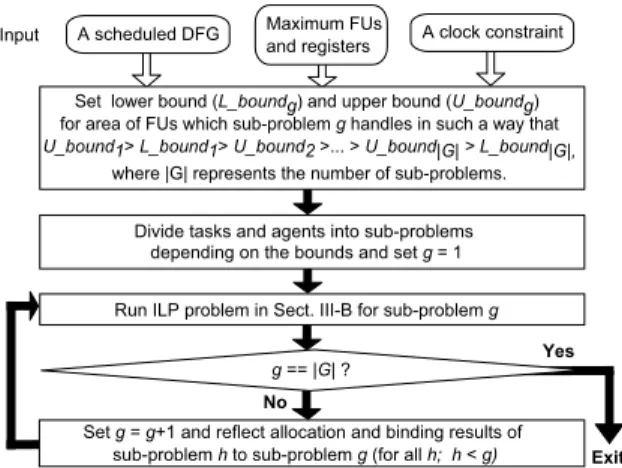
(4) Vol.2011-SLDM-148 No.15 2011/1/17 IPSJ SIG Technical Report . . .. . . .. v1. v3. v2 1. 1. X1. 2. cstep t. 2. +1 1. 2. +2 v5. v4. . . .. . . .. (a). Input. Tasks Agents REG1 v1 REG2 v2 REG3 v3 MULT1 X1 ADD1 +1 ADD2 +2 REG1 v4 REG3 v5. A scheduled DFG. Maximum FUs and registers. A clock constraint. Set lower bound (L_boundg) and upper bound (U_boundg) for area of FUs which sub-problem g handles in such a way that U_bound1> L_bound1> U_bound2 >... > U_bound|G| > L_bound|G|, where |G| represents the number of sub-problems. Divide tasks and agents into sub-problems depending on the bounds and set g = 1 Run ILP problem in Sect. III-B for sub-problem g. (b) Yes. Fig. 2 Path delay estimation: (a)A part of an input scheduled DFG and (b)A binding result.. g == |G| ? No Set g = g+1 and reflect allocation and binding results of sub-problem h to sub-problem g (for all h; h < g). e.g., value v1 and operation ×1 are assigned to register REG1 and multiplier M U LT 1, respectively. For example, a path p1 in Fig. 2(a) starts from value v2, passes through the 2nd operand of ×1 and the 1st operand of +2, and ends at value v5. Then, in case of the binding result in Fig. 2(b), the delay of path p1, dp1 , is estimated as a summation of the delays of REG2, a MUX inserted before the 2nd input port of M U LT 1, M U LT 1, a MUX inserted before the 1st input port of ADD2, ADD2, a MUX inserted before the input port of REG3, and REG3; dp1 = DelayREG2 + DelayM U XnM U LT 1,2 + DelayM U LT 1 + DelayM U XnADD2,1 + DelayADD2 + DelayM U XnREG3,1 + DelayREG3 . Then, in order to meet the clock constraint, ConstDelay, all paths should meet the following constraint; dp ≤ ConstDelay ∀p ∈ P ath (6). 3.3 ILP-Based Heuristic In this section, we present a heuristic based on the ILP problem described in Sect. 3.2. In medium- and large-scale designs, our ILP problem might be unable to handle allocation and binding for all tasks at one time in practical time because the number of formulas rapidly grows by increasing the number of variables, xi,j . However, by using the ILP-based heuristic which splits the entire problem into several smaller sub-problems and stepwisely solves the FU/register allocation and binding problem, an optimal or near-optimal solution can be obtained in practical time. This approach is effective to handle non-small designs. This algorithm focuses on how expensive each type of FUs is in area since sharing more expensive FUs more effectively decreases the datapath area. Fig. 3 shows the stepwise allocation and binding algorithm. Let us explain it by the example in Fig. 1(a). First, a designer sets lower and upper bounds of FU area for sub-problems in such a way that sub-problem g contains more expensive FUs than sub-problem g+1. Assume that the entire problem is divided into subproblems 1 and 2 for the example in Fig. 1(a), we set the bounds so that only multipliers are in sub-problem 1 and adders are in sub-problem 2. Second, FUs and operations assignable to the FUs are divided into the sub-problems depending on the bounds. Because FU/register binding results interdependently influence each other, operations and their input/output values should be handled together in the same sub-problem. If the values are input to (output from) multiple types. Area: The objective of this study is to simultaneously conduct FU/register binding and allocation so that the datapath area (i.e., the total resource area) is minimized. That is, while meeting the above constraints, the value of the following cost function should be minimized; X X M in : (Areaj + AreaM U Xnj,m ) × yj (7) j∈Agents. Exit. Fig. 3 Stepwise allocation and binding algorithm.. mth port∈InP ortsj. P where yj = 1 if at least one task is bound to agent j (i.e., i∈T asks xi,j ≥ 1), otherwise 0. Although for simplicity, we described the formulation in non-linear form, it can be easily linearized such as by a linearization option of ILP solvers.. 4. c 2011 Information Processing Society of Japan °.
(5) Vol.2011-SLDM-148 No.15 2011/1/17 IPSJ SIG Technical Report Table 3 Area and delay of hardware resources.. Table 2 Characteristics of benchmark programs.. ADD SUB MULT SHIFT CMP REG?1 2-to-1 3-to-1 4-to-1 MUX MUX MUX Area (LUTs) 32 32 512 62 52 32 32 64 96 Delay (ns) 2.11 2.11 8.09 0.89 2.30 0.00 0.17 0.56 0.56. Complexity of input DFGs Designs FFT HAL IDCT3 IIR Biquad. add 4 2 5 6. Minimum FUs and registers (Given allocation in 1)) sub mult shift cmp value ADD SUB MULT SHIFT CMP REG 4 4 18 2 2 2 6 2 6 1 25 1 1 4 1 10 3 2 2 21 3 3 2 2 7 2 5 19 1 1 2 6. library17) , are shown in Table 3. The clock constraint for our method was set for 8.33ns (120MHz). Our method was solved in two steps for all the designs. 4.2 Experimental Results Table 4 summarizes experimental results. The third, fourth, and fifth columns show used resources (i.e., FUs, registers, and MUXs), the total resource area, and the critical path delay, respectively. Our work necessarily meets the clock constraint with the minimum resource area. On the other hand, 1) violates the constraint in all the designs because 1) focuses on only minimizing the total number of interconnections and does not care where MUXs are inserted. One may think that the constraint violation by 1) is trivial. Actually, the violation might be small in small designs. However, the larger the design becomes, the more serious the violation will be because MUX insertion on a critical path will be inevitable under limited resource allocation, especially if the path delay is not considered. Our work can minimize the total resource area under the clock constraint by simultaneously optimizing allocation and binding while considering where the MUXs would be inserted. The LINGO’s runtime was in total from approximately seven to 80 minutes for our method and from approximately one to 55 minutes for 1). While the ILP problem of 1) was solved at one time and obtained optimal solutions, our method was solved in the stepwise manner and the obtained solutions may be near-optimal. Even so, our method outperforms 1) in that our method explores the wider design space and obtains solutions with the minimum area under the clock constraint, which cannot be explored by 1). Here, we showed only the results where 1) violates the clock constraint in all the designs. If a looser constraint which 1) meets is given, solutions obtained by 1) are always contained in the design space which our method explores. That is, those solutions or better solutions (i.e., solutions with smaller area) are obtained as optimal solutions by our method.. of operations in different sub-problems, the values should be handled with more expensive operations. For this example, multiplication ×1 and its input/output values v1,v2,v4 are handled in sub-problem 1, and the other tasks are in subproblem 2. Next, the ILP problem in Sect. 3.2 is run for all sub-problems in descending order of expensiveness of FUs which the sub-problems hold. Results of all precedence sub-problems (i.e., allocation, binding, MUX insertion, and critical path information) should be reflected to their successive sub-problems. For this example, the results of sub-problem 1 is reflected to sub-problem 2. It is repeatedly done until all the sub-problems are solved. 4. Experiments This section demonstrates the effectiveness of our method through experiments. 4.1 Experimental Setup In experiments, the ILP problem in Sect. 3.2 was solved in a stepwise manner as described in Fig. 3 by a commercial ILP solver, LINGO12) , with its linearization option. To evaluate the efficiency of our work, we compared our work with 1), one of the recent works which the most effectively minimize MUXs by simultaneous FU/register binding under given allocation. Although 1) presented a heuristic and an ILP formulation for solving the problem and its contribution is the proposal of the heuristic, we also solved its ILP problem by LINGO for comparing the optimality of our work and 1). We used the following four designs as benchmarks: FFT13) , HAL14) , the third stage of MPEG IDCT (IDCT3)14) , and the IIR Biquad filter consisting of N sections (IIR Biquad)15) . The designs were scheduled by a commercial HLS tool, eXCite16) . For 1), the minimum numbers of FUs and registers for the given scheduled DFGs are given as allocation. Table 2 describes complexity of DFGs and the allocation for 1) in columns 2-7 and 8-13, respectively. Utilized resources deal with 32 bit data, and their area and delay, based on the Xilinx Virtex-4’s. ?1 On FPGAs, registers are generally implemented by flip-flops. Here shows the equivalent number of LUTs for a 32-bit register. Also, for simplicity without loss of generality, we assume that load/store time of registers is 0.00ns.. 5. c 2011 Information Processing Society of Japan °.
(6) Vol.2011-SLDM-148 No.15 2011/1/17 IPSJ SIG Technical Report Table 4 Experimental results. Desgins FFT. Methods Our work Existing work1) HAL Our work Existing work1) IDCT3 Our work Existing work1) IIR Biquad Our work Existing work1). ADD ADD ADD ADD ADD ADD ADD ADD. × × × × × × × ×. 2, 2, 1, 1, 3, 3, 2, 1,. SUB SUB SUB SUB SUB SUB SUB SUB. × × × × × × × ×. 2, 2, 1, 1, 3, 3, 2, 1,. MULT MULT MULT MULT MULT MULT MULT MULT. × × × × × × × ×. 2, 2, 4, 4, 2, 2, 2, 2,. Resources Area (LUTs) Critical path delay (ns) REG × 7, 2-to-1 MUX × 6 1,568 8.26 REG × 6, 2-to-1 MUX × 7 1,568 8.43 CMP × 1, REG × 12, 2-to-1 MUX × 7 2,772 8.26 CMP × 1, REG × 10, 2-to-1 MUX × 6, 3-to-1 MUX × 1 2,740 8.65 SHIFT × 2, REG × 11, 2-to-1 MUX × 5, 3-to-1 MUX × 1 1,916 8.26 SHIFT × 2, REG × 7, 2-to-1 MUX × 5, 4-to-1 MUX × 2 1,916 8.65 REG × 7, 2-to-1 MUX × 5, 3-to-1 MUX × 1 1,600 8.26 REG × 6, 2-to-1 MUX × 5, 3-to-1 MUX × 2 1,568 9.21. 4) C.-J. Tseng and D.P. Siewiorek, “Automated synthesis of data path in digital systems,” IEEE Trans. on Computer-Aided Design of Integrated Circuits and Systems, vol. CADJ, no.3, pp. 379–395, 1986. 5) C.-Y. Huang, Y.-S. Chen, Y.-L. Lin, and Y.-C. Hsu, “Data path allocation based on bipartite weighted matching,” in Proc. Design Automation Conference, 1990, pp. 499–504. 6) B. Pangrle, “On the complexity of connectivity binding,” IEEE Trans. on Computer-Aided Design of Integrated Circuits and Systems, vol.10, no.11, pp. 1460– 1465, 1991. 7) M.Rim, R.Jain, and R.De Leone, “Optimal allocation and binding in high-level synthesis,” in Proc. Design Automation Conference, 1992, pp. 120–123. 8) T.Kim and X.Liu, “Compatibility path based binding algorithm for interconnect reduction in high level synthesis,” in Proc. International Conference on Computer Aided Design, 2007, pp. 435–441. 9) J. Cong, Y. Fan, and J. Xu, “Simultaneous resource binding and interconnection optimization based on a distributed register-file microarchitecture,” ACM Trans. on Design Automation of Electronic Systems, vol.14, no.3, pp. 1–31, 2009. 10) N.Woo, “A global, dynamic register allocation and binding for a data path synthesis system,” in Proc. Design Automation Conference, 1991, pp. 505–510. 11) C.Mandal, P.P. Chakrabarti, and S.Ghoseo, “GABIND: A ga approach to allocation and binding for the high-level synthesis of data path,” IEEE Trans. on Very Large Scale Integration Systems, vol.8, no.6, pp. 747–750, 2000. 12) Lindo systems. [Online]. Available: http://www.lindo.com/ 13) N.Ohsawa, M.Hariyama, and M.Kameyama, “FPGA-based processor for multimedia mobile communication,” in Proc. Sensing Instrument Control Engeneering Tohoku Chapter workshop, 2000, pp. 1–6. 14) Express group. [Online]. Available: http://express.ece.ucsb.edu/ 15) V.Sivojnovic, J.M. Velarde, C.Schlager, and H.Meyr, “Designing the low-power mcore architecture,” in Proc. Signal Processing Applications & Technology Conference, 1994. 16) Y Explorations. [Online]. Available: http://www.yxi.com/. 17) Xilinx Inc. [Online]. Available: http://www.xilinx.com/.. 5. Conclusions In this paper, we proposed a novel simultaneous allocation and binding method which minimizes the datapath area (i.e., the total area of FUs, registers, and MUXs) while meeting a clock constraint. By considering not only the area of MUXs but also where the MUXs would be inserted in a circuit, our method explores the wider design space than existing works and obtains solutions which meet the clock constraint with the minimum datapath area. We formulated this method as an ILP problem. Also, we presented an effective ILP-based heuristic for non-small designs. Experimental results showed that our work more globally optimizes circuits under a clock constraint than an existing work. As designs become larger, even our ILP-based heuristic may be unable to solve in practical time. Developing a heuristic which can handle such large designs will be our future work. Also, the influences of the controller and routing logic on the area and performance of the circuits should be considered in our future work. Acknowledgements This work is in part supported by KAKENHI 22700050. References 1) J.Cong and J.Xu, “Simultaneous FU and register binding based on network flow method,” in Proc. Design, Automation and Test in Europe, 2008, pp. 1057–1062. 2) Y.Hara, H.Tomiyama, S.Honda, and H.Takada, “Proposal and quantitative analysis of the CHStone benchmark program suite for practical c-based high-level synthesis,” Journal of Information Processing, vol.17, no.12, pp. 242–254, 2009. 3) P.G. Paulin, J.P. Knight, and E.F. Girczyc, “HAL: A multi-paradigm approach to automatic data path synthesis,” in Proc. Design Automation Conference, 1986, pp. 263–270.. 6. c 2011 Information Processing Society of Japan °.
(7)
図

関連したドキュメント
The mass error was confirmed using 200 μg/L Fusarium toxin standards in neat solvent, a corn sample spiked with 100 μg/kg standards of Fusarium toxins, and a reference corn
The conventional conditions for synthesis of 3- ethoxycyclobutanones by [2 + 2] cycloaddition of ethyl vinyl ether (EVE) and ketene, which was generated in situ from carboxylic
In this paper, using Steffensen’s inequality we prove several inequalities (The- orems 1.1 and 1.2) involving Taylor’s remainder.. In Sections 3 and 4 we give several applications
The SLE-revised (SLE-R) questionnaire despite simplicity is a high-performance screening tool for investigating the stress level of life events and its management in both community
An example of a database state in the lextensive category of finite sets, for the EA sketch of our school data specification is provided by any database which models the
For the second part of the Theorem 2, one can filter the order types, which allow a simultaneous embedding of the triangulations from Phase 2 and 4, and then – using CPLEX or Gurobi
Using the results proved in Sections 2 and 3, we will obtain in Sections 4 and 5 the expression of Green’s function and a sufficient condition for the existence and uniqueness
In Section 4, by using Lashkevich’s construction of vertex operators in the GKO construction, an isomorphism is given between the fusion product of level 1 and level k
