Japan Advanced Institute of Science and Technology
JAIST Repository
https://dspace.jaist.ac.jp/
Title
DOUBLE SYMBOL ERROR RATE AND BLOCK ERROR RATE OF
MDPSK
Author(s)
Adachi, F.; Matsumoto, T.
Citation
Electronics Letters, 27(17): 1571-1573
Issue Date
1991-08-15
Type
Journal Article
Text version
publisher
URL
http://hdl.handle.net/10119/4804
Rights
Copyright (c)1991 IEEE. Reprinted from
Electronics Letters, 27(17), 1991, 1571-1573.
This material is posted here with permission of
the IEEE. Such permission of the IEEE does not in
any way imply IEEE endorsement of any of JAIST's
products or services. Internal or personal use of
this material is permitted. However, permission
to reprint/republish this material for
advertising or promotional purposes or for
creating new collective works for resale or
redistribution must be obtained from the IEEE by
writing to [email protected]. By choosing
to view this document, you agree to all
provisions of the copyright laws protecting it.
Description
current density of 1.81 k A c n - ’ for broad area lasers (50pm x 300pm) was obtained at 628 nm. H. MURATA Y. TERUI M. SAITOH Y. SATOH R. TERASAKl
Electronic Material Department Research Center
Denki Kagaku Kogyo Co., Ltd. 3-5-1 Asahimachi
Machidashi, Tokyo 194, Japan
2nd July 1991
References
1 ISHIKAWA, M., OKUUA, H., ITAYA, K., SHIOZAWA, H.. and UEMATSU, Y.: ‘Long-term reliability tests for InGaAlP visible laser diodes’, Jpn. J. Appl. Phys., 1989,28, pp. 1615-1621
2 KIKUCHI, A., KANEKO. Y., NOMUKA, I., and KISHINO, K.: ‘Room tem- perature continuous wave operation of GaInP/AlInP visible-light laser with GaInP/AllnP superlattice confinement layer grown by gas source molecular beam epitaxy’, Electron. Lett., 1990, 26, pp. 1668-1 669
3 ITAYA, K.. ISHIKAWA, M., and UEMATSU, Y.: ‘63611x11 room tem- perature CW operation by heterobarrier blocking structure InGaAlP laser diodes’, Electron. Lett., 1990, 26, pp. 839-840 and YUASA, I.: ‘632.7nm CW operation (20°C) of AlCalnP visible laser diodes fabricated on (001) 6“ off toward (110) GaAs sub- strate’, Jpn. J . Appl. Phys., 1990, 29, pp. L1669-LI671
YOWSHI, K., and YAMAGUCHI, I.: ‘High-power operation of 630 nm-band transverse-mode stabilised AlGdhP laser diodes with current-blocking region near facets’, Electron. Lett., 1991, 27, pp. 661462
6 HINO, I., WMYo, A., KAWATA, s., KOBAYASHI, K., and SUZUKI, 1.: ‘Magnesium doping of AlGaInP grown by metalorganic chemical vapor deposition’, Inst. Phys. Conf: Ser., 1986, 79, pp. 151-156 7 OHHA, Y., NISHIKAWA, Y., NOZAKI, c., SUGAWARA, H., and NAKANISI,
T.: ‘A study of p-type doping for AlGaInP grown by low-pressure MOCVD, J. Cryst. Growth, 1988,93, pp. 613-617
8 NELSON, A. W., and WESTBROOK, L. D.: ’A study of p-type dopants for InP grown by adduct MOVPE, J . Cryst. Growth, 1984,68, ( I ) , 4 KOHAYASHI, K., UENO, Y., HOTTA, H., GOMVO, A., TAUA, K., HARA, K.,
5 HAMADA, H., SHONO, M., HONDA, S., HlROYAMA, K., MATSUKAWA, K.,
- On-’. Therefore, if noise forces a large phase deviation in
e,-,,
two consecutive symbol errors (double symbol error) are likely t o be produced. Statistics of symbol error patterns affect the FEC performance. In this Letter, the double symbol error rate (DSER) of an M-ary DPSK (MDPSK) system is calcu- lated. When ARQ is used (no F E C is incorporated), retransmission is requested if the received data block contains at least one single error. This Letter also calculates the block error rate (BKER) taking into account the effect of double symbol error.Calculation of DSERr Oberst and Shilling’ calculated the DSER for 2DPSK (or BDPSK). Goldman’ extended the analysis t o MDPSK (however, the calculated results were shown only for M = 2 and 4). We present a simple, approx- imate DSER calculation method and calculate the conditional SER which is defined as the SER when the previous symbol decision was in error.
The phase of detector input signal is fluctuated by additive noise. Let I$ be the phase error of 0,- from the ideal phase point 0 = mn/M, m = 0, 1,
.,.,
M - 1, at decision timet = ( n - 1)T. The nth symbol and (n
-
1)th symbol are cor- rectly detected if the phase errors of 8, and lie between+
+
n / M and+
- n / M . Assuming that noise samples areindependent Gaussian variables, SERs of the nth and ( n - 1)th symbols, when the phase error of 0,- I is
4,
can be given bydLl+)
=d L 1
I+)
=
4
erfc[
~ ( 7 ) sin(’
+
+)]
+
+
erfc[
~ ( 7 ) sin(a
-+)I
-
4
erfc [ ~ ( y ) sin(z
+
+)]
x erfc[J(:;)
sin(’
-
+)]
pp. lo2-llo9 V E U H O ~ , E., B A U M E I ~ ~ ~ , H., TREICHLER, R,, and BRANDT, : ,, 6~~
diffusion during metalorganic vapor phase epitaxy of InP, Appl.
Phlrs r p t t i9xq 55.”” 1m7-1019
where y is the signal-to-noise ratio. Eqn. 1 is a n exact expres- sion for 4DPSK (or QDPSK). For MDPSK with M 2 8,
however it is a n upper bound. Because the third term in the . .. ,l. ._ --, --, rr . . . . . -. .
10 DEPPE, U. G., NAM, U. w., HOLONYAK, N., JUN., HSIEH, K. c., and BAKER, J. E.: ‘Impurity-induced layer disordering of high gap InAlGaP heterostructures’, Appl. Phys. Lett., 1988, 52, pp. 1413- 1415
right hand side of eqn. 1 is negligible for large values of y, eqn. 1 gives a good approximation. SER P(E,) is obtained by averaging p ( E . [ @ ) with the probability density function
p(4)
of I$.2x cos +{ 1
+
erf [ J ( y ) cos +]} (2)DOUBLE SYMBOL ERROR RATE A N D
BLOCK ERROR RATE
OF
MDPSK be calculated fromBecause error events E,, and E , _ , are independent, DSER can
Indexing term: Errors, Digital communication systems The double symbol error rate (DSER) is calculated for an M-ary DPSK (MDPSK) system to show that double symbol errors are less likely lo be produced when M 2 4 than for the binary case ( M = 2) and that MDPSK with M 2 4 provides similar conditional SER (defined as the SER when the pre- vious symbol decision was in error) when compared at the same SER value. The block error rate (BKER) is also shown to be well approximated by that determined assuming inde- pendent symbol error when M 2 4.
Introduction: Error control, such as forward error correction (FEC) and automatic repeat request (ARQ), is often used to improve bit error rate (BER) performance. In M-ary differen- tial phase shift keying (MDPSK) systems, symbol errors tend to be produced in pairs due t o differential detection. When the phase of the signal plus additive noise at decision time t = nT
is represented by 8,, the nth symbol is determined from AB, = 8, - and the (n - 1)th symbol from A8n-l = O n - , ELECTRONICS LETTERS 15th August 1991 Vol. 27 No,
Finally, conditional SER P(E,
I
E,- canbe
obtained from Fig. 1 shows the calculated results of the conditional SERP(E”, E , -
J P W -
1).as a function of signal energy per bit-to-noise power spectrum density ratio ( E b / N , = y/log, M). For comparison, SER is also shown (it was found that SER performance when M L 8 is almost identical with the exact one calculated from Reference 4). It can be seen that the conditional SER of BDPSK decreases very slowly and is larger than that of Q D P S K when
E J N , > 4dB. The conditional SERs at various values of SER were obtained from Fig. 1 and compared in Fig. 2. At an SER of the conditional SERs are 1.8 x l o - ’ for M = 2, 5.0 x lo-’ for M = 4, 3.6 x
IO-’
for M = 8, and 3.4 x IO-’for M = 16. It can be seen that when compared at the same SER value, the conditional SER is largest for BDPSK and those for MDPSK with M 2 4 are similar. The reason why
the conditional SER of BDPSK is larger than those of the other schemes can be qualitatively explained. Because of the larger decision phase margin
(k
n/2) of BDPSK, the (n-
1)th1 0 O F i
0)ill
E b / N 0 , d 6
Fig. 1 Conditional SER MDPSK
-
conditional SER SER_ ~ _ -
symbol is erroneously detected when a large phase error of occurs. However, it is rare for the phase error of 0, to have the same sign and be able to cancel the effect of the previous phase error. This produces double symbol error. As
M increases, however, the decision phase margin decreases and smaller phase error of O n - , causes an error in the
(n - 1)th symbol. Therefore, it is more likely for the phase error of 8, t o cancel the effect of phase error of 0,- 1, so that double errors tend t o be reduced.
i 8 6
M
Fig. 2 Comparison ofconditional SERs at various SERs 0 S E R = lo-’
0 S E R = 1 0 - 3
a
S E R = 10-4Block error rate: Here, BKER is defined as the probability of
the data block containing a t least one single error. An N -
symbol block is assumed. Because nonadjacent symbol deci-
sions are independent, BKER can be calculated from
N - 1
B K E R = 1 - P ( C , )
n
P ( C ,I
C,- 1) (4),= 1
where C, is the event of correction decision for the j t h symbol.
P(C,
I
C, - is identical for any 1, and eqn. 4 can be rewritten a sB K E R = 1 - P(C,) . P N - I ( C ,
I CO)
( 5 )where P ( C , ) = 1 - P ( E , ) , P ( C l
I
CO) = P ( C o , C , ) / P ( C , ) . Note that P ( E , ) = P ( E , ) and P ( C , , C , ) = 1 - 2 P ( E 1 )+
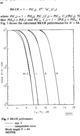
EO, E , ) .Fig. 3 shows the calculated BKER performance for N = 64.
0 4 8 12 16 20 2 4 2 8 E ~ ~, d B N c
ilonl
Fig. 3 BKER performance
~ eqn. 5
_ _ _ _ independent error Block length N = 64 MDPSK
Eqn. 5 can be approximated as
B K E R E N . P(EJC1 - P ( E I IE0)I (6)
for a high EJN,. If symbol errors are independent, then B K E R = 1 - { 1 - P(Eo)lN E N , P ( E , ) . Hence, the BKER with differential detection is smaller by a factor of 1
-
P ( E ,I
E,) than that experienced with independent symbol error. It is found from Fig. 1 that the BKER of BDPSK becomes 72% of that determined assuming independing symbol error when E d N , = 8dB. For M t 4, however, because 1 - P(El IE,) is very small, the effect of double symbol error is negligible. This is confirmed by Fig. 3 in which BKER performance is plotted assuming independent symbol error.Conclusion: The conditional SER of MDPSK with M 2 4 is much smaller than that of BDPSK when compared a t the same SER value. The effect of double symbol errors on BKER is negligible and therefore BKER is well approximated by that determined assuming independent symbol error when M 2 4. F. ADACHI
T. MATSUMOTO
N T T Radio Communication Systems Laboratories 1-2356 Take
Yokosuko-shi, Kanagowa-ken 238, Japan
5th July 1991
References
I OBERST, J. F., and SCHILLING, 0. L.: ‘Double error probability in
differential PSK, Proc. IEEE, June 1968, pp. 1099-1100
GOLOMAN, J.: 'Multiple error performance of PSK systems with cochannel interference and noise', I E E E Trans., August 1971, COM-19, pp. 42W30
BENNETT, w. R.: 'Method of solving noise problems', Proc. IRE, May 1956,44, pp. 609-538
PAWULA, R. F.: 'Asymptotics and error bounds for M-ary DPSK, IEEE Trans., January 1984, COM-32, pp. 93-94
NOVEL LEAKY-WAVE ANTENNA FOR MILLIMETRE WAVES BASED O N V-GROOVE GUIDE
Indexing terms: Antennas, Waveguides
A novel type of leaky-wave antenna for millimetre waves based on the V-groove guide is described. A complete trans- verse equivalent network is presented for analysis and design of this new leaky-wave antenna. Numerical results for the performance characteristics of the antenna are given.
Introduction: The groove guide is potentially attractive as a low-loss waveguide in millimetre wave and submillimetre wave bands. Recently this kind of waveguiding structure has attracted increasing attention because of its advantages such as low-loss nature, ease of fabrication, large structural dimen- sions and higher power handling capacity. A leaky-wave antenna constructed from the groove guide was described and investigated by Oliner and L a m p a r i e l l ~ . ' - ~ This leaky groove guide antenna overcomes two problems that leaky-wave antennas for millimetre wave ranges often face: lower wave- lengths and higher metal loss. The V-groove guide is an alter- native t o the rectangular-groove guide. The new structure exhibits lower attenuation and more effective rejection of
higher order modes. Based on the V-groove guide, we present
a new type of leaky-wave antenna. An accurate analysis, based
on a transverse equivalent network, is presented for the properties of this leaky structure that takes into account the mode conversion from the bound mode t o the leaky mode. Using this analysis, numerical design values can be readily obtained. The antenna structure is therefore able to be easily understood and systematically designed.
A n a l y s i s : The cross-section of the new leaky-wave antenna is shown in Fig. 1. As in References 1-3, it is the added contin-
uous strip of width 6 that introduces asymmetry into the basic V-groove guide and creates the leakage. The strip therefore gives rise to an additional transverse mode and couples that mode t o the original transverse mode which by itself would be purely bound.
yQ-Px
O a - - - - __ _ _ - _ - -
- -
-
b
1117111
Fig. 1 Cross-section of new leaky-wave antenna based on V-groove
guide
The transverse equivalent network for the cross-section of the structure shown in Fig. 1 is given in Fig. 2. This network is based on these two transverse modes, which propagate in the x direction and are coupled by the narrow asymmetrical strip. These coupled transverse modes then combine t o produce
a
net T E longitudinal mode (in the y direction) with a complex propagation constant j3-
ja. In the network, the i = 1 trans- mission lines represent the original mode with a half-sinewave variation in the y direction in Fig. 1, and the i = 0 transmis- sion lines represent the new mode which has no variation with y. In the central region, the tapered lines represent the Vgroove, which can be analysed by a numerical integration technique. The detailed formulation of the analysis method for the tapered lines can be found in a recent paper.s
Fig. 2 Complete transverse equivalent network for structure whose
cross-section is shown in Fig. I
The expressions for the various constituents of this network can be found in References 3 and 6. The final expression for j3
and a can be derived by the application of the transverse resonance condition. 0 '
'
'
"'
' '
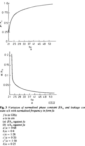
' 21 2 5 29 33 37 41 45 49 53 fa a f0 bFig. 3 Variation of normalised phase constant Plk, and leakage con- stant aik with normalised frequency in form f a
IS in GHz Lis in cm ( a ) Pik, against f a ( b ) aJk, against f a a'/a = 0.68 bia = 0.4 cja = 1.28 c'ja = 0.20 c"/a = 1.50 Sja = 0-25
Numerical results: We have obtained numerical values in graphical form of the variation of j3 and a with each of these dimensional parameters, so that design optimisation can proceed in a systematic fashion. However, we present here, in Figs. 3a and b, respectively, only the curves of j3/k and a / k as a function of fa (where f is the frequency in G H z and a is the width of the central region in cm). It can be seen that the performance of the new V-groove guide leaky-wave antenna is very similar to that of the leaky rectangular-groove guide antenna. Because the cutoff wavelength of the V-groove guide is bigger than that of the rectangular-groove guide with the