Hirundo: A Mechanism for Automated Production of
Optimized Data Stream Graphs
Miyuru Dayarathna
Department of Computer Science, Tokyo Institute of Technology,
2-12-1 Oookayama, Meguro-ku, Tokyo 152-8552, Japan
[email protected]
Toyotaro Suzumura
Department of Computer Science, Tokyo Institute of Technology and
IBM Research - Tokyo 2-12-1 Oookayama, Meguro-ku,
Tokyo 152-8552, Japan
[email protected]
ABSTRACT
Stream programs have to be crafted carefully to maximize the performance gain that can be obtained from stream pro- cessing environments. Manual fine tuning of a stream pro- gram is a very difficult process which requires considerable amount of programmer time and expertise. In this paper we present Hirundo, which is a mechanism for automatically generating optimized stream programs that are tailored for the environment they run. Hirundo analyzes, identifies the structure of a stream program, and transforms it to many different sample programs with same semantics using the no- tions of Tri-Operator Transformation, Transformer Blocks, and Operator Blocks Fusion. Then it uses empirical opti- mization information to identify a small subset of generated sample programs that could deliver high performance. It runs the selected sample programs in the run-time environ- ment for a short period of time to obtain their performance information. Hirundo utilizes these information to output a ranked list of optimized stream programs that are tailored for a particular run-time environment. Hirundo has been developed using Python as a prototype application for op- timizing SPADE programs, which run on System S stream processing run-time. Using three example real world stream processing applications we demonstrate effectiveness of our approach, and discuss how well it generalizes for automatic stream program performance optimization.
Categories and Subject Descriptors
I.2.2 [Computing Methodologies]: Automatic Program- ming—Program transformation, Program synthesis; H.3.4 [Information Systems]: Systems and Software—Distributed systems
Permission to make digital or hard copies of all or part of this work for personal or classroom use is granted without fee provided that copies are not made or distributed for profit or commercial advantage and that copies bear this notice and the full citation on the first page. To copy otherwise, to republish, to post on servers or to redistribute to lists, requires prior specific permission and/or a fee.
ICPE’12, April 22–25, 2012, Boston, Massachusetts, USA Copyright 2012 ACM 978-1-4503-1202-8/12/04 ...$10.00.
General Terms
Performance, Design, Measurement, Algorithms
Keywords
Stream processing, performance optimization, fault toler- ance, data-intensive computing, scalability
1. INTRODUCTION
Importance of high performance data stream processing has been emphasized more than ever before due to appear- ance of many online data stream sources. Until now there have been two dominant stream programming models called relational model [3] and operator-based model [18][10]. With the introduction of commercial stream processing systems such as IBM InfoSphere Streams [24] and open source ini- tiatives like Yahoo S4 [21], it can be expected that operator- based stream processing systems may play a key role in fu- ture high performance stream computing undertakings.
As we pointed out in [10], High performance of a stream program is characterized not only by its structure, but also by the topology and performance characteristics of the stream processing system on which it runs. Nevertheless stream pro- grams deployed on most of the stream processing systems may produce low performance while they continuously re- ceive huge amounts of input data, and while there are abun- dant computational resources under utilized by the run-time environment.
One solution for this issue is to manually fine tune the pro- gram to consume unused system capacity. This will lead to faster processing of input data leading to a higher through- put [27]. However, this requires tremendous amount of pro- grammer’s time and expertise since there are various differ- ent ways an operator-based stream program can be written that gives the same semantics but widely different perfor- mance characteristics. Sometimes programmer needs to port the program to a different run-time environment that offers totally different performance characteristics. Furthermore, in production environments run-time topology may change quite frequently. E.g. Existing nodes of the run-time may be brought down for maintenance. Therefore, this approach costs a lot for organizations, and might not be practical in certain production environments.
Another solution for this problem is to conduct a profile driven optimization. Results from profiling can be used to
characterize the run-time behavior of operators [32], and an optimization model can be created to come up with higher performing alternatives. However, we address the problem of performance optimization from the point of view of the pro- grammer because source level design decisions could affect the entire application’s performance even if profile driven optimization is used. Since we do not modify the com- piler/scheduler during the optimization process, our approach can be generalized to different operator based stream pro- cessing systems easily.
Given an operator-based stream program, we describe a method for automatically identifying the best version of the program that is suited for a particular stream processing run- time environment. In achieving our goal, we first identify the structure of the stream program (i.e. input program). Then we transform the data flow graph of the program to a number of different data flow graphs (i.e. sample programs) preserving program semantics. Then we choose a subset of sample programs using the information gathered from previ- ous similar performance optimization attempts (we call this performance prediction). Next, a subset of the chosen sam- ple programs are run in the stream processing run-time, and their performance information are gathered. Based on the results of analyzing the performance information such as throughput, elapsed time, etc., a ranked subset of sample programs are identified as the output that provides better performance compared to input program. An optimization mechanism prototype based on System S was implemented using Python to evaluate the feasibility of our approach.
To the best of our knowledge this is the first such attempt made to automate the construction of optimized stream pro- grams. Use of the term “Optimized” here means deriving effi- cient stream programs that can harness the full performance of stream processing environment they run on. Specifically, our contributions in this paper can be stated as follows,
• Tri-Operator Transformation : We introduce a novel method of transforming operator-based data flow graph of a stream program without violating its semantics.
• Transformer Blocks : We describe the use of collections of operators as transformation primitives during the optimization process.
• Stream Program Performance Prediction : Hirundo uses empirical data of similar optimization attempts to reduce the effort required for identifying optimized program versions.
• Stream Program Performance Characterization : Us- ing K-means clustering on Hirundo’s database, we de- scribe a method of identifying common characteristics of high/low performing programs, which would bene- fit stream programmers in producing high performance stream programs.
• Fault Tolerance : Hirundo emphasizes the importance of fault detection in the run-time environment during the process of optimization in order to ensure accuracy of the results it produces.
The paper is structured as follows. We describe related work for Hirundo in Section 2 and provide an overview for
SPADE language in Section 3. We describe the methodol- ogy in Section 4. The concepts of Tri-Operator Transforma- tion, Operator Blocks Fusion, and Transformer Blocks are described in Sections 5, 6, and 7 respectively which forms the basis of our methodology. We describe how we narrow down the search space for optimized sample programs in Section 8. Measures taken to ensure the semantically correctness of the sample programs is described in Section 9. Fault tolerance of Hirundo is explained in Section 10. We give implemen- tation details of Hirundo in Section 11. Evaluation details of our prototype system are given in Section 12. Next, we discuss the achievements of our objectives and limitations of our current prototype under the Section 13. Finally we present some further work and conclude in Section 14.
2. RELATED WORK
Optimization of data flow graphs has been widely ad- dressed research issue.
Early efforts in automatic parallelization of sequential pro- grams studied methods for automatic data partitioning and distribution of computations in distributed-memory multi- computer systems [8][22][6]. However, the distributed com- puting model handled by these works differ from stream com- puting model. Hirundo concentrates more on computations that are data-intensive, and does not conduct any static code optimizations like these works.
Automatic composition of workflows has been addressed by Quin et al. [23] and Liew et al. [19]. Compared to them, Hirundo concentrates on automatic optimization in the con- text of stream computing, and ensures the optimization pro- cess does not get affected by node failures. This issue has not been addressed by these works.
Hirundo introduces use of Transformer blocks during its data flow graph transformations in the context of stream computing. There has been similar use of recurring patterns for optimizing workflows by Liew et al. [29] and Hall et al. [13].
There has been works on performance prediction of par- allel applications by partial execution [30] using skeletons [26] etc. Furthermore, recent relational data base servers use empirical cost information for producing optimized query plans [7][1][17]. Yet, Hirundo follows a different approach for identifying optimized sample programs by integrating results from partial execution of sample programs with empirical data.
Subquery optimization of relational database systems by Bellamkonda et al. [7] has similarity to what Hirundo does since both the approaches use code transformation as the means of optimization. Table partitioning in relational data- bases is a technique used for optimizing SQL query perfor- mance [14]. This technique is analogous to Hirundo’s Tri-OP Transformation.
Stream graph partitioning [18][28] tackles the problem of stream program performance optimization at lower levels of stream processing environment compared with the approach followed by this work. Hirundo approaches the solution from the source program level of a stream application.
Recently there has been interest of automatically optimiz- ing programs written for MapReduce systems [4]. Similarly compiler of DryadLINQ [31] system performs static opti- mizations which enables automatic synthesis of optimized
LINQ code. However, these systems do not perform high level code transformations like Hirundo does during the pro- cess of optimization. Hirundo outputs a ranked list of op- timized sample programs, whereas these systems performs their optimizations in lower levels.
3. SPADE - AN OPERATOR-BASED
STREAM PROCESSING LANGUAGE
Hirundo has been designed for optimizing operator-based data stream programs. Current implementation of Hirundo has been developed on top of System S [12] stream processing system and SPADE language [12][16].
Stream programs developed based on operator-based pro- gramming model are organized as data flow graphs consist- ing of operators and streams [18]. Operators are the smallest possible building blocks that are required to deliver the com- putation an application is supposed to deliver. Streams are directed edges that connect pairs of operators, and carries data from source to destination operators.
SPADE language (the latest version is referred to as Stream Processing Language (SPL) [15]) consists of two types of operators called composite and primitive operators [15]. A composite operator consists of a reusable stream subgraph that can be invoked to define streams. Primitive operators are basic building blocks of composite operators. Primitive operators can be further categorized in to built-in opera- tors (BIOP), user-defined operators (UDOP), raw UDOPs, and user-defined built-in-operators (UBOP). In this paper we mainly concentrate on BIOPs since current Hirundo im- plementation supports a subset of BIOPs (Source, Functor, Aggregate, and Sink). Out of them, Source operator is used to create a stream from data flowing from an external source [16]. It is capable of parsing, creating tuples as well as inter- acting with external devices [16]. A Sink operator converts a stream of data from the program into a flow of tuples that can be used by external entities. Functor operator on the other hand, is used for performing tuple-level manipu- lations such as filtering, projection, mapping, attribute cre- ation, and transformation etc. Aggregate operators are used for grouping and summarization of incoming tuples.
4. METHODOLOGY
Hirundo accepts a stream program and a sample data file as input. The input data file is segmented in to collections of sample input data files. Input program is analyzed to iden- tify Operator Blocks. An operator block is simply a collec- tion of operators (1 or more) that is identified by Hirundo’s grammar. After Hirundo identifies all the operator blocks present within the input program it generates sample pro- grams (S) (More details are given in next section). Based on current processing environment’s profile information [11] and learnings from previous optimization runs, Hirundo selects a subset (U1:U1⊂S;|U1|=n) from the sample programs. The subset U1 is compiled using parallel compiler of Hirundo, and the resulting programs are run in the stream processor environment for a time window Wt. A ranked list of pro- grams R1(R1:R1⊂U1; |R1|=m; m < n) is selected based on the performance results obtained by running the programs. R1 is merged with a next best subset of programs U2 from S (U2:U2⊂S;U1∩U2=∅;|U2|=n-m) to form U3. All the pro-
grams in U3 are run in the stream processing environment. Similar to previous case, a ranked list of R2 (R2:R2 ⊂U3;
|R2|=m; m < n) is selected as the output. This process is shown in Figure 1.
Analyze Program Structure Generate similar programs with
different flow graph layouts
Run each program in U1for Wttime
A ranked list of programs
(R2)
Input
Sample data file
Synthesize sample data Sample Programs
(S)
Select programs
U1
Compile programs U3
parallel
Output Select
programs U2
Select programs
R1
Run each program in U3for Wttime
Compile programs U1
in parallel
Calculate performance details,
rank programs
stream program
Figure 1: Methodology of Hirundo
5. TRI-OPERATOR TRANSFORMATION
As described in Section 1, we introduce a methodology for transforming a stream program to a variety of sample appli- cations, which are used as sample programs for optimization process. Our method is based on Parallel Streams design pattern [5]. We term the algorithm that does this transfor- mation as Tri-Operator Transformation (i.e. Tri-OP Trans- formation). The algorithm transforms data flow graphs by three operator blocks at a time.
Trades
& Quotes
results
S F1 AG
Pass 1 Pass 2
Pass 3
Key S – Source Fn – Functor n AG – Aggregate SI – Sink
F2 SI
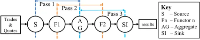
Figure 2: Data flow graph of Volume Weighted Average Price application and how it is traversed by GENERATE() pro- cedure.
5.1 Concept
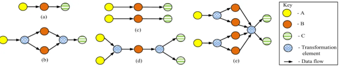
Lets consider three adjacent operator blocks (an operator block is a collection of operators) A, B, and C in a data flow graph (Shown in Figure 3(a)). From here onwards we will denote such operator block as A B C. Note that we use the term “operator block” to denote each A, B, and C as well as A B C because A B C itself is a collection of operators.
The aim of Hirundo’s data flow graph transformation is to generate a variety of data flow graphs for a given stream program. We have chosen to transform 3 adjacent operator blocks at a time due to several reasons. First, while choos- ing more than 3 operator blocks would have enabled us to create more sophisticated data flow graphs, we decided to stick with 3 operator blocks due to simplicity of transforma- tion logic involved with 3 operator blocks. Second, transfor- mation logic should not increase number of operators expo-
nentially. Changing the number of middle operator blocks (i.e. operator block B shown in Figure 3(a)) in a 3 opera- tor blocks combination, we can achieve this feature easily. Furthermore, use of 3 operator blocks at a time allows us to generate higher variety of patterns than the variety of patterns that could be generated using only two operator blocks.
5.1.1 Transformer Patterns
In the rest of this paper we will use the notation i-j-k (i, j, k are positive integers including 0) to denote a transfor- mation pattern. Pseudocode of transform() procedure in Algorithm 3 explains how an operator block A B C is trans- formed by an i-j-k pattern.
Algorithm 1 tri_op_transform(G, d) Algorithm 2 generate(G, i, j, k) 1: oblist ← emptylist
2: for i ← 0 to d do 3: for j ← 0 to d do 4: for k ← 0 to d do 5: outdictionary ← generate(G, i, j, k) 6: oblist.add(outdictionary) 7: end for
8: end for 9: end for 10: weld(oblist, len(G))
1: m ← 0 2: v ← getroot(G) 3: while v has next do
4: invarray ← getnextthreevertices(v) 5: if length[inarray] = 3 then
6: tvarray[m] ← transform(invarray, i, j, k) 7: m ← m + 1
8: v ← invarray[2] 9: end if 10: end while 11: return (tvarray)
Tri-OP transformation does not do any change to A B C operator blocks if it transforms using the pattern 1-1-1. The meaning of 1-1-1 can be described as follows. Keep one A, increase the number of Bs to 1 × 1, and map transformed B operator blocks to one C. Tri-OP transformation does not consider any other patterns having only 0s or 1s (e.g. 0- 0-0, 0-0-1) other than the pattern 1-1-1 to avoid duplica- tion. Transformation pattern 1-2-1 transforms A B C in to A 2B C (See Figure 3(b)). This means that keep one A, in- crease the number of Bs to two, and map the two Bs to one C. This is an example for increase of middle operator blocks. Minimum number of middle operator blocks is 1.
Tri-OP transformation creates a single B when it finds j=0. E.g. When transformation pattern 2-0-2 is applied to A B C, it results in 2A B 2C (Shown in Figure 3(d)). In this example two As are mapped to a single B. Then streams from B are mapped to two Cs. The value of j plays an impor- tant role in describing the structure of the resulting operator block. Lets take the scenario of applying 2-1-2 transforma- tion to A B C. This is an example for i = k, j = 1 scenario in Line 13 of Algorithm 3. It will result in 2A 2B 2C, hav- ing two operator blocks from each category (shown Figure 3(c)). Furthermore, these operator blocks will be connected in parallel. Yet when transforming by 2-1-1 it will result in 2A 2B C, which changes number of A and B operators to 2, and keeps single C operator. Similarly 2-2-2 (shown in Figure 3(e)) and 2-2-3 transformation patterns result in 2A 4B 2C and 2A 4B 3C transformed operator blocks re- spectively.
5.2 Algorithm
Lets consider how Tri-OP transformation is conducted on a real world example application of stream computing. We use Volume Weighted Average Price (VWAP ) written using five operator blocks (Described more in the Evaluation Sec- tion) for this purpose. This program’s data flow graph is shown in Figure 2.
After Hirundo accepts the input program it parses the program using Program Structure Analyzer (Described in sub section 11.1). Program Structure Analyzer identifies each operator block and creates a graph (G) that repre- sents the structure of the input program. Graph G is fed to tri_op_transform() procedure (shown in Algorithm 1) along with a depth value d. Depth value d is a positive in- teger that determines to what extent input program will be transformed.
Initially an empty operator block list (oblist) is created. An operator block is represented as a dictionary object. The procedure traverses graph G in steps of 3 operator blocks. This can be observed from the three for() loops (Lines 2-4, Algorithm 1). Each pass generates an i-j-k pattern.
The tri_op_transform() procedure calls generate() pro- cedure passing the graph G and the i, j and k values (Pseu- docode of generate() is shown in Algorithm 2). Functional- ity of the generate() procedure can be visualized using Fig- ure 2. First, generate() procedure moves to the root node of the graph (in the example it is the source operator (S)). Then it selects three adjacent operator blocks from root (S, F1, AG) by calling the procedure getnextthreevertices(), and applies the transformation of the i-j-k pattern by calling transform(). This is termed as the pass1 in Figure 2. Then generate() procedure moves to the neighbor of the root (that is F1), picks three operator blocks (F1, AG, F2) and applies the transformation of i-j-k pattern to them (pass2). Note that we chose the second operator block rather than the fourth operator block because to enable transformation of graphs with vertex counts not belonging to multipliers of three. Finally it applies transformation of i-j-k pattern to operator blocks AG, F2, SI (pass3). If there are n operator blocks present in a data flow graph, generate() procedure does the i-j-k pattern transformation n-2 times. The result- ing n-2 operator blocks are saved in a dictionary. We call these operator blocks as Transformed Operator Blocks. The keys (i.e. labels) of the transformed operator blocks are cre- ated using i,j,k values and the input operator block names (i.e. A, B, and C). The dictionary gets saved in the oblist (See line 6 of Algorithm 1).
Finally tri_op_transform() procedure calls weld() pro- cedure (shown in Algorithm 4) by passing the transformed operator blocks list (oblist) and the input program graph length (glen) to weld() (glen is 5 for the VWAP application shown in Figure 2). The weld() procedure selects matching operator blocks from oblist, and fuses them to create sample programs. (Concept of fusion is described with more details in Section 6.) As shown in Algorithm 4, weld() procedure traverses the list of transformed operator blocks that it re- ceived. If a particular operator block has one or more source operators (i.e. It is a source operator block), the procedure creates a matched operator blocks list (fList). Then it finds matching operator blocks for source operator block by calling findoblist()(Line 5 in Algorithm 4) and stores in another operator block list (tList). The pseudocode of findoblist() procedure is shown in Algorithm 6. If tList is not empty it means that there are matching operator blocks for source op- erator. In this case transformed operator blocks list received from generate() procedure (oblist), tList, fList, maximum depth of traversal (glen - 3) are fed to a recursive procedure called getmatchob() as shown in Line 7 of Algorithm 4.
(a)
(b)
(c)
(d) (e)
- A - B Key
- C
- Transformation element - Data flow
Figure 3: Some Sample Transformations using Tri-OP transformation. (a) Input operator blocks (b) Result of applying 1-2-1 transformation (c) Result of transforming by 2-1-2 (d) Result of transforming by 2-0-2 (e) Result of transforming by 2-2-2
Algorithm 3 transform(A_B_C, i, j, k) Algorithm 4 weld(oblist, glen) 1: if i = 1 and j = 1 and k = 1 then
2: return A_B_C 3: end if
4: if all i, j, k are 0 or 1 then 5: return
6: end if
7: if i = 0 or k = 0 then 8: return
9: end if 10: if j = 0 then 11: return iA__B_kC 12: end if
13: if j = 1 and i = k then 14: return parallel(iA_iB_iC) 15: end if
16: return iA_(i×j)B_kC
1: fList ← emptyList 2: for all oblock in oblist do 3: if oblock is sourceoblock then 4: fList ← add(fList, oblock) 5: tList ← findoblist(oblist, oblock) 6: if tList not empty then
7: getmatchob(oblist, tList, fList, glen - 3) 8: end if
9: end if 10: end for 11: filter()
12: for all fusion in fusionList do 13: resprog ← fuse(oblist, fusion) 14: save(resprog)
15: end for
1: for all ob in tList do 2: if ob is sinkoblock then 3: fList.add(ob) 4: fusionList.add(fList) 5: else
6: if depth <= 0 then
7: return
8: end if
9: kList ← findoblist(oblist, ob) 10: if kList is not empty then 11: for all obk in kList do 12: fList.add(obk)
13: return getmatchob(obList, kList, fList, depth - 1) 14: end for
15: end if 16: end if 17: end for
Algorithm 5 getmatchob(oblist, tList, fList, depth)
The pseudocode of getmatchob() is shown in Algorithm 5. It finds matching operators for every operator in the trans- formed operator block list (oblist), and adds them to fu- sionList, which is a globally defined list that holds the final result. Next, it appends operator block ob to fList. A call to getmatchob()procedure returns a matched operator block list which keeps lists of matching operator blocks (fusions) in sequential order. After getmatchob() completes execution, the duplicate operator blocks in fusionList are removed by calling filter() procedure (Line 11 of Algorithm 4). Then weld()procedure fuses each and every fusion that is stored with in the fusionList to construct sample programs. A fu- sion in Lines 12-13 in Algorithm 4 refers to a sample pro- gram with operator blocks which are not fused yet. Merging of operator blocks located in each individual fusions is done by fuse() procedure (Line 13).
6. OPERATOR BLOCKS FUSION
A typical stream program may consist of minimum three operators. They are Source, a computational operator (e.g. Functor/Aggregate etc.), and Sink. Transformation of such program directly creates sample programs since the three operators represent three operator blocks. However, in most of the scenarios more than 3 operator blocks are present in stream programs. In such occasions more than one trans- formed operator blocks are created by generate(). These transformed operator blocks need to be stitched together meaningfully (i.e. with same semantics) to produce sample programs. Synthesis of sample programs in such occasions is called Operator Blocks Fusion.
A fusion mentioned in the previous section is a list of op- erator blocks which are arranged in a sequential order which makes a complete sample program (semantically equivalent to input program) if they are concatenated. Ordering of operator blocks is done based on the decision given by is- match() procedure call shown in Algorithm 7. The is- match()procedure determines whether two operator blocks
opb1 (iA jB kC) and opb2 (mX nY pZ) should be fused or not based on their operator types (A,B,C,X,Y,Z) and the transformation pattern values (i,j,k,m,n,p). For two trans- formed operator blocks opb1 and opb2 to match with each other, first and the second operators of opb2 should be the same as the second and third operators of opb1 (See Line 1 of Algorithm 7). (i.e. X ≡ B and Y ≡ C ). This is the primary requirement for opb1 to match with opb2. Next, if the opb2’s last operator block (i.e. Z) is a Sink operator block then if m = 1 and n = p then opb1 and opb2 matches with each other (See Lines 4 to 7 of Algorithm 7). If opb2’s last operator block is not a sink operator block then if the conditions k = (m×n) and m = 1 holds, opb1 and opb2 are considered matching with each other. (Note: the function names fopb(), sopb(), topb(), and inopb() correspond to first operator block, second operator block, third operator block, and index of operator block respectively).
7. TRANSFORMER BLOCKS
Hirundo uses a set of generic operator blocks called Trans- former Blocks during transformation of a data flow graph. These are introduced in between the identified operator bloc- ks to create coupling between resulting operator blocks (trans- formed operator blocks) of Tri-OP transformation.
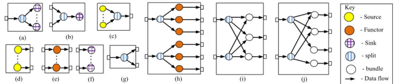
MUX-SINKis a transformer block that multiplexes an input stream in to n number of sink operators (shown in (a) of Figure 4). The opposite of this operation, de-multiplexing of several streams in to a single sink operator is done by DEMUX-SINK(see (b) in Figure 4). DEMUX-SOURCE transformer block merges n number of source operators in to one single stream. Yet, multiple streams from n number of source op- erators can be obtained using PARALLEL-SOURCE transformer block. MULTI-FUNCTOR transformer block creates n number of functor blocks. Similar to PARALLEL-SOURCE, PARALLEL- SINK transformer block creates n number of sink operator blocks. A stream is converted to multiple streams using MUX-STREAMtransformer block. MUX-FUNCTOR-N-TO-M trans-
Algorithm 6 findoblist(oblist, ob) Algorithm 7 ismatch(opb1, opb2) Algorithm 9 getprogramlabels(optrunList, n) 1: if sopb(opb1) = fopb(opb2) and topb(opb1) = sopb(opb2) then
2: inopb1 ← getIndexes(opb1) 3: inopb2 ← getIndexes(opb2) 4: if inopb2[1] = 1 then
5: if topb(opb2) = ‘SI’ and inopb2[2] = inopb2[3] then
7: return true
8: else if inopb1[3] = (inopb2[1]*inopb2[2]) then
9: return true
10 else 11: return false 12: end if 13: end if 14: end if
1: inproglabels ← getinputproglabels() 2: alldict[label, avgdifflist] ← emptyDictionary 3: for all optrunid in optrunList do 4: labelslist ← getSampleProgLabels(optrunid) 5: filtlist ← removeInputProgLabels(labelslist, inproglabels) 6: labeldict[label, perfvalue] ← getperfvals(optrunid, filtlist) 7: perfdict[label, avgdiff] ← getAvgPerfvalDiffs(labeldict) 8: alldict.append(perfdict)
9: end for
10: rlabels ← sortUsingAveragePerfDiffAsc(alldict) 11: result_labels ← selectTopN(rlabels, n) 12: return result_labels
1: optrunList ← getOptruns(metrics, tschema)
2 : optrunList ← sortUsingTransformationDepth(optrunList, d) 3: optrunList ← sortUsingMatchingIndices(G, optrunList) 4: optrunList ← sortUsingMatchingNodes(nodePerf, optrunList) 5: optrunList ← selectTopN(optrunList, m)
6: return optrunList
Algorithm 8 getmatchingoptruns(G, nodePerf, metrics, d, m, tschema) 1: tList ← emptyList
2: for all oblock in oblist do 3: if ismatch(ob, oblock) then 4: tList.add(oblock) 5: end if 6: end for 7: return tList
former block creates n×m number of functor blocks accept- ing n input streams. TRANSFORMER-N-TO-M is a transformer block that accepts N number of input streams which can output M number of streams (see (i) of Figure 4). A slightly different transformer block to TRANSFORMER-N-TO-M called TRANSFORMER-MODULUS-N-TO-Maccepts N input streams and outputs M streams. However, in the latter scenario, symme- try of the internal operators is not preserved. This can be observed from (j) of Figure 4.
Transformer blocks are created as supporting primitives for Tri-OP transformation process. They are reusable and useful when Hirundo is updated to support new operator types in future. While Tri-OP transformation algorithm concentrates on increasing/decreasing number of operator blocks in a data flow graph, transformer blocks concentrate on solving the problem of how to make links (i.e. streams) between the operators in transformed operator blocks. Trans- former blocks should not be confused with similar constructs such as Composite Operators of IBM Stream Processing Lan- guage [15].
Furthermore, the decision of mapping output streams from split operators of transformer blocks such as TRANSFORMER- N-TO-M, TRANSFORMER-MODULUS-N-TO-M, etc. has been taken in order to preserve the isometry of data flow graph. Isom- etry of a data flow graph is an important factor for highly availability of a stream application [18].
8. SAMPLE PROGRAM RANKING
Hirundo’s data flow graph transformation algorithm gen- erates many sample programs for a given input program. E.g. 32 sample programs are generated for regex applica- tion during an optimization run with d = 4. Running all these sample programs for small time period may take time in the order of minutes. E.g. Running all the aforemen- tioned 32 sample programs (+input program) in a System S environment with 8 nodes took 17 minutes and 22 sec- onds (an average calculated over 7 optimization runs). We observed that performance of a stream program in a cer- tain environment can be repeated. Hence we can predict up to a certain level, what kind of performance could be obtained from a stream program using empirical data. We have implemented an algorithm (The Algorithms 8 and 9 corresponds to this prediction process.) in Hirundo that predicts similarity of optimization runs considering the pa- rameters of structure of data flow graph (G), performance metrics used (e.g. throughput, elapsed time), optimization run depth (d), input data tuple schema (tschema). Hirundo
uses a relational database to store its information. Current optimization environment’s profile information such as num- ber of hosts, CPU, RAM capacity are stored in the database prior to any optimization attempt. All the important opti- mization run information (i.e. optimization session informa- tion) such as start time, end time, performance metrics used are recorded in the database. Furthermore, performance in- formation (i.e. throughput, elapsed time, etc.) of each sam- ple program which ran during the optimization session are also stored in this database.
In this mode of operation Hirundo predicts what kind of performance could be obtained from the input program. Al- gorithm 8 first selects a list of optimization runs based on the optimization metric used and the input data tuple schema. Next, it sorts the list based on the transformation depth and the structure of the input data flow graph (i.e. A,B,C val- ues of the graph A B C). Finally the optimization runs are sorted based on node performance values, and top m opti- mization runs are selected as matching optimization runs. Next, these optimization run ids are fed to the getprogram- labels()procedure shown in Algorithm 9 to obtain sample program labels to run. For each optimization run, the per- formance differences of sample programs are gathered, and stored in a dictionary called alldict. The items in the dic- tionary are sorted based on their performance difference val- ues in ascending order. The top n labels of this sorted list are selected as the candidate labels. These n labels correspond to the U1 subset of the sample program labels mentioned in Section 4 (Methodology Section), and the remaining steps of the Methodology Section are followed to obtain a ranked list of sample programs (R2) as the output. We use such method of two phase ranking in order to increase the accuracy of the end result. Section 12 demonstrates results we obtained by operating Hirundo in this mode.
9. PRESERVATION OF INPUT PROGRAM
SEMANTICS
We took two key measures to ensure the semantically equivalence of the sample programs to their input program. We believe these measures preserve the semantics of all the input programs processed by Hirundo. First, Operator Block Fusion uses fusions that have the same operation type se- quence similar to input program. Second measure is related to the problem of Stateful Operators in Parallel stream de- sign pattern described in [6]. Hirundo provides the notion of annotations to ensure semantically correctness of sam- ple programs with Stateful Operators. E.g. The sample
- Source - Functor Key
- Sink - split
- Data flow
… …
…
… …
(a) (b)
(e)
(c)
(d) (f) (g) (h) (i) (j)
- bundle
Figure 4: Some Sample Transformer blocks used by Hirundo. (a) MUX-SINK (b) DEMUX-SINK (c) DEMUX-SOURCE (d) PARALLEL-SOURCE(e) MULTI-FUNCTOR (f) PARALLEL-SINK (g) MUX-STREAM (h) MUX-FUNCTOR-N-TO-M (i) TRANSFORMER-N-TO-M (j) TRANSFORMER-MODULUS-N-TO-M
programs generated for the VWAP application shown in Figure 2 may produce semantically wrong code if AG,F2, and SI operator blocks are transformed to multiple opera- tors by Hirundo. In order to avoid this, the SPADE code corresponding to AG,F2, and SI operators can be enclosed between two Froze annotation tags (these are marked as
#Hirundo-meta:Froze:Startand #Hirundo-meta:Froze:End in program code). When code generator finds an opera- tor block A B C having one or more operator blocks be- ing marked as frozen, it makes sure that transform() pro- cedure does not change the number of operator blocks in the corresponding transformed operator block that is out- put for A B C. Furthermore, we checked the output tuples of randomly chosen sample programs with each correspond- ing original input program’s output and got confirmed that they produce the same outcome.
10. FAULT TOLERANCE OF HIRUNDO
Compared to many related work mentioned in Section 2, Hirundo emphasizes the importance of fault tolerance during automatic program optimization process. Hirundo strives to eliminate instance failures that might occur in the stream processing environment. An instance failure is just failure of a run-time instance (i.e. a process spawned by stream processing environment). Unexpected failures may occur in stream processing environment when such automatic opti- mization process has been conducted. While the stream processing run-time could continue with the remaining set of instances, it may not reflect the actual performance that could have been achieved by using a sample program. Ul- timately this may lead to an inaccurate ranking of sample programs. Note that there are no such recording made dur- ing the experiments mentioned in this paper since all the faults were successfully resolved by Hirundo.
We have observed that certain large sample programs over- load the run-time instances, and they might run out of mem- ory creating instance failures. Finding the set of sample programs that provide highest performance without break- ing the stream processing run-time environment’s stability is a challenging issue. Hirundo uses streamtool of System S periodically to obtain the health information of the System S runtime, and compares those information with the runtime snapshot (original health record) obtained at the beginning of the optimization run to detect failures. (Note that at the very beginning of the optimization run, Hirundo displays the original health record to user, and gets it confirmed free of
faults). If found a failure, Hirundo tries to restart the run- time, and compares the health of the newly started runtime with the original health record. If the status of the runtime was restored, it starts running the interrupted job (sample program). It follows the same procedure during three con- secutive failures. If it cannot succeed, it marks the sample program as a failure (by recording throughput as -1) and continues the optimization run.
11. IMPLEMENTATION
Hirundo has been implemented using Python program- ming language. It has been separated in to two modules called Main module and Worker module. Architecture of Hirundo is shown in Figure 5.
Hirundo
SPADE program Input Sample data file
Program Structure Analyzer Data Preparator
Program Generator
Parallel Compiler
Worker WorkerWorker
Worker Worker Performance
Meter
SPADE Compiler A ranked list of programs
Output Program
Ranker
Hirundo grammar
Netwo Serve
Figure 5: System Architecture of Hirundo.
Current version of Hirundo has been developed target- ing stream programs written using SPADE language. Hence Hirundo depends on System S and SPADE compiler during its operations. It should be noted that, although System S is dependent on a shared file system such as NFS, Hirundo has been designed not to use such file systems for optimization runs. It uses local hard disks to store the data it handles during optimization runs. Hirundo uses a SQLite database to store its information. Main module has been separated in to ten sub modules based on different functionalities they handle. We briefly describe functions of important modules below.
11.1 Program Structure Analyzer
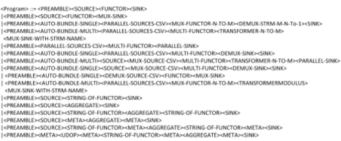
SPADE program analysis logic has been implemented in Program Structure Analyzer of Hirundo. As pointed out in Section 5.2, Hirundo uses a bespoke grammar written for parsing a SPADE program to identify its structure. Cur- rent implementation of Hirundo’s grammar supports Source, Functor, Aggregate, Sink BIOPs, and UDOPs (with the use of annotations described in Section 9). This module uses an LALR parser [2]. Hirundo’s parser has been developed using the GOLD parser generator developed by Cook et al. [9]. The grammar has been coded separately from Hirundo (independent of Python programming language), and can be modified easily using the GOLD parser generator [9]. Cur- rent version of the grammar consists of 34 rules. Only the rule that defines the structure of a program is shown in Fig- ure 6. Program analyzer creates a representative graph G for the program it analyses if it can identify its structure. This graph keeps details of all the operators (vertices) identified from the program and the links between them.
<Program> ::= <PREAMBLE><SOURCE><FUNCTOR><SINK>
|<PREAMBLE><SOURCE><FUNCTOR><MUX-SINK>
|<PREAMBLE><AUTO-BUNDLE-SINGLE><PARALLEL-SOURCES-CSV><MUX-FUNCTOR-N-TO-M><DEMUX-STRM-M-N-To-1><SINK>
|<PREAMBLE><AUTO-BUNDLE-MULTI><PARALLEL-SOURCES-CSV><MULTI-FUNCTOR><TRANSFORMER-N-TO-M>
<MUX-SINK-WITH-STRM-NAME>
|<PREAMBLE><PARALLEL-SOURCES-CSV><MULTI-FUNCTOR><PARALLEL-SINK>
|<PREAMBLE><AUTO-BUNDLE-SINGLE><PARALLEL-SOURCES-CSV><MULTI-FUNCTOR><DEMUX-SINK><SINK>
|<PREAMBLE><AUTO-BUNDLE-MULTI><SOURCE><MUX-SOURCE-CSV><MULTI-FUNCTOR><TRANSFORMER-N-TO-M><PARALLEL-SINK>
|<PREAMBLE><AUTO-BUNDLE-SINGLE><SOURCE><MUX-SOURCE-CSV><MULTI-FUNCTOR><DEMUX-SINK><SINK>
| <PREAMBLE><AUTO-BUNDLE-SINGLE><DEMUX-SOURCE-CSV><FUNCTOR><MUX-SINK>
| <PREAMBLE><AUTO-BUNDLE-MULTI><PARALLEL-SOURCES-CSV><MUX-FUNCTOR-N-TO-M><TRANSFORMERMODULUS>
<MUX-SINK-WITH-STRM-NAME>
|<PREAMBLE><SOURCE><STRING-OF-FUNCTOR><SINK>
|<PREAMBLE><SOURCE><AGGREGATE><SINK>
|<PREAMBLE><SOURCE><STRING-OF-FUNCTOR><AGGREGATE><STRING-OF-FUNCTOR><SINK>
|<PREAMBLE><SOURCE><META><AGGREGATE><META><SINK>
|<PREAMBLE><SOURCE><STRING-OF-FUNCTOR><META><AGGREGATE><STRING-OF-FUNCTOR><META><SINK>
|<PREAMBLE><META><UDOP><META><STRING-OF-FUNCTOR><META><AGGREGATE><META><SINK>
Figure 6: A sample rule from Hirundo’s Grammar.
11.2 Data Preparator
Unlike most static program optimizers, Hirundo runs se- lected sample programs for fixed time period in the stream processing environment to identify their performance. The sample programs require representative data during their ex- ecution. Data Preparator is the module that creates these required sample data. At the beginning of optimization pro- cess, user should provide a sample data file along with input program. This file is splitted in to total [d(d+1)/2 - 1] num- ber of files staring from the groups 2, 3, up to d. The number d is the depth value that is accepted by Tri-OP transfor- mation algorithm. The files are splitted in this way since Tri-OP transformation with depth d may produce d num- ber of maximum transformed source operator blocks for any optimization run. Furthermore, such splitting ensures that all the input data are received by all the source operators of the sample programs homogeneously. User should enter only required size input data file (smaller size file is preferred) to Hirundo since very large files impose unnecessary overhead on Hirundo during its optimization runs. Furthermore, we use a file rather than online data source in order to keep the input fixed during all the optimization attempts the input program faces since this could directly affect the end result of program ranking.
11.3 Parallel Compiler
Hirundo would have spent substantial portion of its pro- cessing time on compilation, if Hirundo were to compile all the sample programs on a single node. E.g. Compiling
VWAP (25 programs), regex (33 programs), and Twitter (27 programs) applications described in this paper on a sin- gle node takes approximately 11, 43, 50 minutes respectively. To reduce total time taken for compilation we created a par- allel compiler for Hirundo. Current version of Hirundo de- ploys one worker per each node of the node cluster of which it operates on during its instantiation. Parallel compiler as- signs compilation task of a single program to one worker. We were able to reduce the percentage of time required for compilation of VWAP, regex, and Twitter applications to 5, 7, and 8 minutes resulting 51%, 84%, and 84% compilation time reduction respectively on 8 nodes.
12. EVALUATION
12.1 Experimental Environment and Method-
ology
The experiments were performed on a cluster of Linux Cent OS release 5.4 installed with IBM Infosphere Streams Version 1.2. Each machine (i.e. node) has a dual core AMD Opteron(tm) Processor 242, 1MB L2 cache per core, 8GB memory, 250GB hard drive, 1Gigabit Ethernet. In the first half of the experiments we disabled the sample program ranking of Hirundo, and made it to run all the sample pro- grams it generated for a short period of time (less than 1 minute). In the second half we enabled the sample program ranking of Hirundo. In all of these experiments Hirundo ensured that the experiments are not affected by sudden in- stance failures by re-instantiating the run-time environment, and re-running the sample program that faced the instance failure. The graphs in Figures 8, 9, 10, and 11 show re- sults of single runs (i.e. No average values were considered). We used three different real world stream applications dur- ing these evaluations. Note that program labels on X axis are shown increasing order of operator indexes from left to right. Each point corresponds to one sample program’s per- formance during one optimization run.
The first application is the Volume Weighted Average Price Application (VWAP) shown in Figure 2. The data flow graph of VWAP application contains 5 operators including two Functors (F1 and F2) and an Aggregate operator (AG). F1 filters the tuples for valid records. AG finds the maxi- mum/minimum of the trading prices using a sliding window of size 4 and outputs a tuple for each tuple it receives. F2 makes arithmetic operations on tuple data fields to create a volume weighted average price. The input data file size is 2.4 MB.
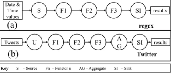
The second application is a data converter application (regex ) (Shown in Figure 7 (a)). This application also con- sists of five operators including three functors (F1, F2, and F3). It converts an input data stream with date time data tuples represented as 2011-04-14 to 14-APR-2011. Further- more, all the “00”s in the time portion of the tuple are re- placed with “22”s. F1 filters the date time data tuples from the stream it receives from SI. Date time format conversion is done by F2. F3 does the replacement of “00”s with “22”s. Input data file size is 8.5 MB.
Third application is a Twitter hash tag counter application (Twitter ). This is a 6 operator application (shown in Figure 7 (b)) including one UDOP (U), three Functors (F1, F2, and F3), and an Aggregate operator (AG). UDOP reads data
Date & Time values
results
S F1 F2 F3 SI
Key S – Source Fn – Functor n AG – Aggregate SI – Sink
results
F1 F2 F3 A
G SI
U Tweets
(a)
(b)
regex
Figure 7: Data flow graphs of regex and Twitter applica- tions.
from a dump of twitter data (size ≈ 181 MB). F1 tokenizes the tweets, and F2 extracts hash tags from the words. F3 eliminates empty tuples. AG aggregates hash tag tuples, emits the has tag count for every 10 tuples it receives, and emits summary of results for each tuple it receives.
12.2 Sample program performance
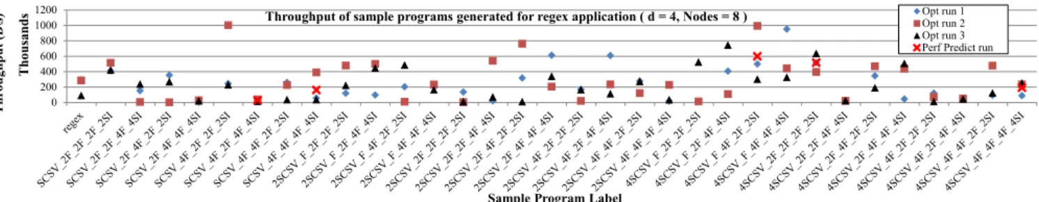
First, we disabled the performance prediction and sample program ranking feature of Hirundo. Therefore, the appli- cation ran the entire sample program space. We compared throughput of sample programs for three optimization runs using 8 nodes in each session. We use the term “Optimization run (Opt run)” to denote a single running of Hirundo in this mode. Our intention is to observe the performance char- acteristics of each sample program generated by Hirundo. Each optimization run had a transformation depth value of 4 for regex and Twitter. For VWAP we set the depth value to 8 since a depth of 4 produced few sample programs for VWAP application. Hirundo generated 32, 24, and 26 sam- ple applications for regex, VWAP and Twitter respectively. From the three graphs it can be observed that certain sample programs produce higher throughput compared to the input application (e.g. 4SCSV 2F 2AG 2F 2SI in the case of regex, 8SCSV 6F F AG F SI in the case of VWAP and U 4F 2F F AG SI for Twitter). Note that the notation used for sample program labels represents the arrangement of operator blocks in the resulting sample programs. E.g. In Twitter sample application U 4F 2F F AG SI, the label means there is one UDOP, four F1s, two F2s, one F3, one AG, and one SI.
12.3 Performance Prediction
We enabled the performance prediction and sample pro- gram ranking feature of Hirundo. In this mode each ex- periment completed in less than 15 minutes time, a 50% reduction of total experiment time compared to without use of performance prediction. The results are shown in the corresponding graphs on Figures 8,9, and 10. Two out of five sample programs had higher performance compared to regex application, whereas the sample programs pointed out for VWAP had higher performance for two out of the three optimization runs. In the case of Twitter application all the four sample programs predicted by Hirundo had higher performance compared to original Twitter application.
Next, we ran a completely different application (numap- plong) which had never been optimized by Hirundo before (results shown in Figure 11). It has similar structure to regex application, but all the three functors chained together in- cremented an integer they received (each operator by 100).
Only one out of the four programs predicted by Hirundo had higher performance than numapplong application. However, after running two optimization runs in non-predictive mode we ran another optimization run with prediction enabled. Three out of five sample applications pointed by Hirundo had higher performance compared to the original version.
12.4 Performance Clusters
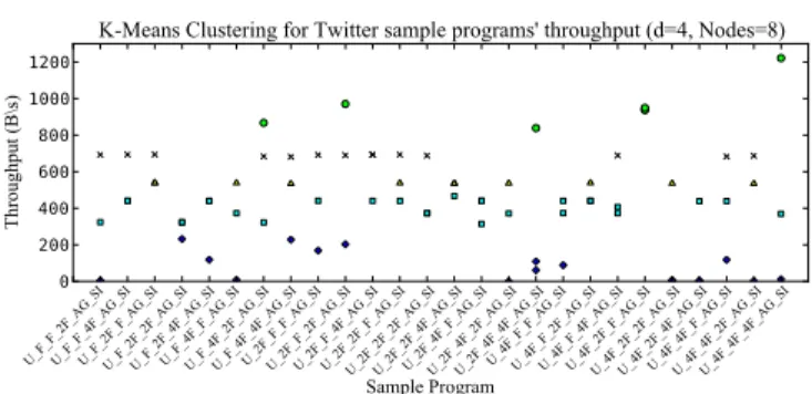
We conducted a cluster analysis on the data sets corre- sponding to Opt run 1, 2, and 3 of each performance curves of Figures 8,9, and 10. Our intention was to find the char- acteristics of data flow graphs which lead to higher perfor- mance. We used K-Means clustering [20] for this purpose since we needed to group the data points based on their per- formance values, and the data sets were of convex shape. We set the minimum gap between the clusters as 100B/s. The algorithm was implemented using Python and Scipy [25] and the results are shown in Figures 12, 13, and 14. We calcu- lated average performance values of each clusters, and also recorded program labels if all the three data points corre- sponding to the three optimization runs fall in to a particular cluster.
VWAP data set resulted in 5 clusters. We saw that the cluster with the highest performance (6393B/s) had all the three data points corresponding to label 8SCSV 6F AG F SI whereas the second highest cluster (3885B/s) had all the three data points corresponding to the label 8SCSV 4F AG - F SI. However, two low performance clusters had all the data points corresponding to the labels SCSV 8F AG F SI and 2SCSV F AG F SI. This indicates that having large num- ber of source operators would produce high throughput in the case of VWAP application described in this paper.
The clustering results for Twitter application is somewhat different than the VWAP because Twitter application’s UD- OP was frozen during program transformation. The highest performing cluster (961B/s) had all data points correspond- ing to the label U 4F 2F F AG SI, whereas a medium per- formance cluster (2nd cluster from the lowest end, having 440B/s performance) had all the data points corresponding to labels U 2F 4F F AG SI. The difference between these programs is that there are more mid level operators (F2, F3 in Figure 7) in low performing one, and there are more F1 operators in the high performance one. It is clear that having more tokenizer Functors (F1) has supported for high performance for Twitter sample applications.
Regex application’s highest performing cluster did not in- clude all the three points form any sample application. How- ever, the second highest performing cluster (474.67KB/s) had all the three data points of SCSV 2F 2F 2F 2SI and 4SCSV 2F 2F 2F 2SI. The cluster with lowest performance (25KB/s) had all the points of labels 4SCSV 4F 2F 4F 4SI, 4SCSV 2F 2F 4F 4SI, SCSV 2F 4F 4F 4SI, SCSV 4F 2F - 4F 4SI. When comparing these two clusters it is clear that having a variety in the number of middle operators has pro- duced less performance for regex application.
13. DISCUSSION AND LIMITATIONS
Our intention of this paper was to introduce a method- ology for automatically producing optimized versions for a given data stream program. Our approach produced higher performance gains (1.7,2.3, and 2.9 times for regex, VWAP,
0 200 400 600 800 1000 1200
Throughput (B\s) Thousands
Sample Program Label
Throughput of sample programs generated for regex application ( d = 4, Nodes = 8 ) Opt run 1Opt run 2 Opt run 3 Perf Predict run
Figure 8: Comparison of three optimization runs (Opt run 1,2,3, and Perf Predict) with regex application using equal opti- mization parameters (d=4, nodecount=8)
0 1 2 3 4 5 6 7 8 9
Throughput (B\s) Thousands
Sample Program Label
Throughput of sample programs generated for ✚ ✛AP application ( d = 8, Nodes = 8 ) Opt run 1 Opt run 2 Opt run 3 Perf Predict run
Figure 9: Comparison of four optimization runs (Opt run 1,2,3, and Perf Predict) with VWAP application using equal optimization parameters (d=8, nodecount=8)
0 200 400 600 800 1000 1200 1400
Throughput (B\s)
✎ample Program Label
Throughput of sample programs generated for Twitter application ( d = 4, Nodes = 8 ) Opt run 1Opt run 2 Opt run 3 Perf Predict run
Figure 10: Comparison of four optimization runs (Opt run 1,2,3, and Perf Predict) with Twitter application using equal optimization parameters (d=4, nodecount=8)
0 200 400 600 800 1000 1200 1400
Throughput (B\s) Thousands
Sample Program Label
Throughput of sample programs generated for numapplong app✔cation ( d = 4, Nodes = 8 ) Opt run 1 Opt run 2 Perf Predict 1 Perf Predict 2
Figure 11: Comparison of four optimization runs of numapplong (Opt run 1,2,Perf Predict 1, and Perf Predict 2). Application uses equal optimization parameters in all runs (d=4, nodecount=8)