Feasibility Studies
on Large-Current Capacity
HTS Conductors
for Fusion Magnets
Gourab Bansal
Department of Fusion Science
School of Physical Sciences
The Graduate University
for Advanced Studies
2008
Dedicated to my wife, Sonika and my daughter, Vidhi
Abstract
The feasibility study of large-current capacity High Temperature Superconducting (HTS) conductors suitable for fusion reactor magnets has been carried out in this thesis.
Presently, well-established low-temperature superconductors (LTS), such as NbTi and Nb3Sn, operating at ~ 4 K are being used for producing high magnetic fields in fusion devices like Tore-Supra, LHD, EAST, SST-1, KSTAR, W7-X and are being planned to be used in near future machines such as JT-60SA and ITER. However, the LTS conductors are prone to quench due to the lower specific heats of the materials and therefore lower stability margin at 4 K. The stability margin of LTS conductors further degrades due to non-uniform current distribution among strands, such as observed in Demo Poloidal Coils (DPC). The future fusion energy reactors such as LHD-type force- free helical reactor (FFHR) cannot allow their huge magnets to quench and therefore there is a need to develop high stability conductors to have safer operations. Compared to LTS, HTS possess rather higher stability as they can be operated at elevated temperatures above 20 K, which assures higher specific heats and therefore lower risk of quench. In addition to high stability, high critical current density is expected for HTS materials in high magnetic fields even at elevated temperatures. Moreover, lower refrigeration power is required due to elevated temperature operations.
Owing to the above-mentioned advantages, HTS conductors are considered to be a potential candidate for future fusion energy reactor magnets. However, HTS conductors are presently available only in the wire and tape forms and no large-current (> 10 kA) capacity HTS conductor that can be used for magnet windings (not for current-leads) has been developed yet. Toward the development of large-current capacity HTS conductors, feasibility of large-current capacity HTS conductors suitable for fusion energy reactors is studied in this thesis. We hereby make a new proposal of simple stacking of HTS wires in the conductor form and the focus of this research is on the cryogenic stability of this type of conductors. Due to simple stacking of HTS wires, it is probable to observe inductance mismatching among HTS wires and therefore non-uniform current distribution is supposed to be formed in the conductor. As mentioned above, non-uniform current
distribution is a serious problem for LTS conductors especially with insulated strands. Even though we are proposing HTS conductors, suitable for DC magnets, without insulation between wires to assure good current re-distribution, it is considered to be an important task to investigate the effect of non-uniform current distribution on the conductor stability. In this respect, as the artificial introduction of non-uniform current distribution is rather easy in cable-in-conduit conductors (CICC), the present research was initiated by critically examining the stability of the non-insulated strand LTS CICC with non-uniform current distribution in the conductor. Secondly, we developed a method to examine the effect of non-uniform current distribution on HTS conductors rather directly by utilizing the LTS/HTS hybrid conductor concept. Thirdly, we fabricated 10 kA-class HTS conductors and tested them extensively. Finally, we carried out the HTS conductor design study for the helical coils of FFHR.
We carried out stability margin measurement experiments on a full-scale CICC with non-insulated NbTi/Cu strands by artificially introducing non-uniform current distribution in a controlled way. In our experiments, we found that the stability margin of the conductor reduced significantly due to the non-uniform current distribution, which indicates that non-uniform current distribution is a problem even for non-insulated strand conductors where current re-distribution can take place rather easily. We found that with the non-uniform current distribution, the stability margin reduced by more than one order of magnitude, especially in the transition region between the well-cooled and ill-cooled regions. The limiting current, which separates the well-cooled and ill-cooled regions, was found to be shifted toward lower current values due to non-uniform current distribution in the conductor. We have carried out numerical calculations to simulate the experimental data of stability margin with uniform and non-uniform current distributions and found good consistency between experimental and calculated results.
We carried out ramp rate limitation (RRL) experiments as well and found that the quench current reduced due to non-uniform current distribution for faster ramp rates ranging from 100 A/s to 800 A/s. Hence, our experiments of stability margin measurements with non-uniform current distribution on non-insulated strand CICC clearly suggest that non-uniform current distribution is an important factor to be
considered for large-current capacity LTS conductors. Therefore, the effect of non- uniform current distribution on the stability of HTS conductors should also be examined even though the stability of HTS conductors is supposed to be quite high compared to LTS conductors.
Then, we proposed a unique and innovative experimental method to examine the effect of non-uniform current distribution on the stability of HTS conductors. We prepared an LTS/HTS hybrid conductor, which was the world’s first superconducting conductor using both LTS and HTS together. In a hybrid conductor, layers of Bi-2223/Ag HTS tapes were soldered to form a stabilizer for the LTS wires. Once a normal-zone appears in the LTS wires, the transport current transfers into the HTS part from one layer to another and so on. This is supposed to be a case of extreme non-uniform current distribution in the HTS part. In our experiments at 4.2 K and 7 T bias field, we found that even with this extreme non-uniform current distribution, the HTS part was stable and the conductor did not quench fully even though the transport current was close to the critical current of the HTS part in the hybrid conductor. These experimental results suggest that non-uniform current distribution may not be a problem for the stability of HTS conductors even though many of the HTS wires carry the currents equal to critical currents. However, examination of this problem by direct experiments on real full HTS conductors might be an important future task.
The experiments on LTS/HTS hybrid conductors confirmed that non-uniform current distribution may not be a problem for HTS conductors and therefore the freedom of conductor configuration can be increased for HTS conductors. Thus, we proposed a large-current capacity HTS conductors consisting of simple stacks of HTS wires, which are presently available in tape forms. This is regarded as a new but a controversial proposal, since simple stacking of superconducting strands without transpositions has never been allowed for LTS conductors. As a first step, we fabricated a 10 kA-class (at 20 K, 8 T) HTS conductor using Bi-2223/Ag tapes. The conductor was prepared by stacking HTS tapes in two bundles and then encasing them inside a copper jacket. The conductor size is 12 mm (width) × 7.5 mm (thickness). An innovative technique was
applied to test the HTS conductor at different temperatures from 4.2 K to 30 K. Thin stainless steel heaters were attached to the conductor surface to elevate the temperature and then conductor was insulated by epoxy and GFRP to obtain similar conduction cooling conditions as in future magnets made of HTS conductors. We measured the critical currents of the HTS conductor at 4.2 K, 10 K, 20 K, and 30 K and the results were found to be close to our expectations. We calculated the critical currents of the HTS conductor at different temperatures and a bias field of 8 T (parallel to the ab-plane of the HTS tapes) by taking account of the self-field generated by the transport current in the conductors. The calculated results are found to be in good agreement with the measured critical current, which shows no degradation in HTS conductors due to the handling during the fabrication process.
The stability margin of the HTS conductor was also measured at different temperatures. The conductor was found to be highly stable, as it was expected from the high heat capacity of the conductor at elevated temperatures. The stability test results suggest that HTS conductors possess much higher stability margin compared to their LTS counterparts and therefore are the potential candidates for stable operations of future fusion energy reactors.
We also carried out ramp rate limitation (RRL) tests on the HTS conductors. The results are very encouraging. The conductor did not show any ramp rate limitation behavior even at 1.5 kA/s ramp rate, which was completely different from the observations in the CICC experiment described above. For HTS conductors, the critical currents were found to increase by increasing the ramp rate. This was because the conductor temperature showed lower increase due to the shorter duration of joule heating associated with the appearance of flux-flow resistance. Hence, our preliminary results suggest that RRL may not be a problem for HTS conductors unlike the LTS counterparts. It is considered that the increase of stability also gives this improvement. As our near future tasks, we will test a 10 kA-class HTS conductor using YBCO tapes. The conductor fabrication and sample development work is underway.
Looking at the encouraging results of 10 kA-class HTS conductors, we have started the HTS conductor design as an option for the helical coils of the LHD-type fusion
energy reactor FFHR. We have carried out several studies such as structural, quench detection and protection on the proposed 100 kA-class HTS conductors using YBCO tapes. We have considered aluminum-alloy or stainless-steel as the jacket material options for the HTS conductors. It is found that stainless-steel jacket is more suitable due to its higher strength and larger heat capacity. Our preliminary results suggest that HTS conductors might be promising candidates for the helical coils of FFHR. However, when considering the application of HTS conductors for fusion magnets, many difficult issues, such as the error magnetic fields generated by superconducting shielding currents in HTS tapes and how to make robust coil structures using fragile HTS materials, should be solved. One also has to optimize the cooling method for HTS coils. At the same time, owing to the higher stability of HTS conductors, a new design philosophy for HTS coils should be established unlike the LTS coils, which are primarily based on the cryogenic stability. In these connections, an innovative idea of having rather thin layers of HTS wires within the conductor is also proposed in the present study. By having such a configuration, the bending strain can be minimized to be ~0.05% level so that the winding of coils using these conductors is feasible. Moreover, the problem of error magnetic field generated by shielding currents in the HTS tapes and/or by the occurrence of non-uniform current distribution among tapes due to inductance mismatching is considered to be equivalent as the shift of current centers in the conductors. If the HTS part can be confined in thin layers, the current shift is supposed to be in an acceptable level within the tolerance of winding accuracy.
As a conclusion, through this thesis, it has been found that considering HTS conductors to be used for fusion energy reactor magnets is feasible though a number of issues associated with their development should be solved one by one.
Acknowledgements
It is my great pleasure to acknowledge all the people who helped and encouraged me to complete my thesis research. It would have not been possible to complete my thesis without the support and nice hospitality from the staff at the Graduate University for Advanced Studies (Sokendai) and National Institute for Fusion Science (NIFS).
I am deeply grateful to Dr. Nagato Yanagi who gave me an opportunity to study at Sokendai/NIFS and patiently guided me throughout my thesis research.
I am greatly indebted to Prof. Osamu Motojima for having given me an opportunity to study at the Department of Fusion Science at Sokendai/NIFS. I am also thankful to Prof. Akio Komori, Prof. Noriyoshi Nakajima, Prof. Shoichi Okamura and many other staff at the department for having assisted me to complete my research.
Particularly, I am deeply grateful to Prof. Akio Sagara and Prof. Toshiyuki Mito for giving me a great help by suggesting many modifications to improve my thesis. They suggested us to stress on our own idea of using simple-stacked configuration of HTS tapes for the large-current application, which really made an impact and boosted our confidence. I give my wholehearted thanks to Prof. Yuichi Ogawa for his fruitful comments, as well as for letting me learn about levitated fusion machines using HTS coils. I also appreciate the useful comments given by Prof. Yasuyuki Shirai.
I would like to give my many thanks to Dr. Kazutaka Seo for his steadfast teaching, informative suggestions and kind helps to me, especially to conduct the experiments on SST-1 CICC and to improve my publications. A number of fruitful suggestions and continuous encouragement given by Prof. Kazuya Takahata are highly appreciated. I thank Dr. Tsutomu Hemmi for his continuous help and support, especially for my experiments and numerical calculations using ANSYS and FEM analysis.
I would like to thank many other staff at NIFS, Prof. Shinsaku Imagawa, Prof. Arata Nishimura, Prof. Takeo Muroga, Prof. Motoyasu Sato, Prof. Yasuji Kozaki, Dr. Shuichi Yamada, Dr. Hirotaka Chikaraishi, Dr. Ryuji Maekawa, Dr. Hitoshi Tamura, Dr. Akifumi Iwamoto, Dr. Shinji Hamaguchi, Dr. Tetsuhiro Obana, Dr. Yoshimitsu Hishinuma and Mr. Sadatomo Moriuchi for giving me many good suggestions and
I am grateful to Ms. Shihomi Kato for taking care of my administrative and personal documents. I would like to give my thanks to our lab staff, Ms. Ai Okada, Mr. Hiroshi Kitano and Mr. Kenji Ueda for their kind helps during my experiments. Special thanks are given to administration staff Mr. Satoshi Ido, Ms. Satona Urushihara, Ms. Kazuko Mizuno, Ms. Kyoko Shimazaki and others for their kind support and help. I am thankful to Ms. Naho Hayashi who taught me Japanese language, which helped me a lot in my daily life and to learn Japanese culture. I would like to give my special thanks to Ms. Emiko Yanagi for her kind supports to my family throughout the last three years.
Special thanks are given to Dr. Teruo Izumi, Dr. Yuh Shiohara, Dr. Yutaka Yamada and Dr. Takashi Saitoh for having provided the YBCO and GdBCO HTS tapes.
I am deeply indebted to the financial support provided by Kakuyugo-Kagaku- Kenkyu-kai, Gifu Prefecture, and Japan Society for the Promotion of Science.
I am deeply grateful to Institute for Plasma Research (IPR) in India and Director- General Prof. Predhiman K. Kaw for granting me a three-year leave to complete my Ph.D. I am grateful to my project leader Prof. Yogesh C. Saxena for his support and encouragement. I would also like to give my thanks to all of my friends for their friendship and support, especially Mr. Malay Chowdhuri, Mr. Dashrath Sonara, Mr. Akhilesh Singh, Mr. Ashu Sharma, Dr. Mainak Bandyopadhyay, Dr. Biswanath Sarkar, Mr. Amit Srivastava, Mr. Ananta K. Sahu, Mr. Ravi Duggar, and Dr. Vipul Tanna.
I am indebted to my members in India for their moral support to me and to my family, especially my parents, my elder brothers Mr. Sanjay Kumar, Mr. Ajay Kumar, Mr. Rajkumar and my younger sisters and brother Ms. Rachna Mittal, Ms. Ritu Garg, Mr. Manish, and my parents in law.
I sincerely dedicate this thesis to my beloved wife Sonika and my sweet daughter Vidhi for their unconditional love and support to me.
Contents
Abstract
Acknowledgement
1.
Introduction 1-281.1. Low temperature superconductors (LTS)………..1
1.2. High temperature superconductors (HTS)………....7
1.3. Application of superconductors in fusion devices………....11
1.4. Issues associated with large-current capacity superconducting conductors………...14
1.5. Advantages of high temperature superconductors………..20
1.6. Objective: Proposal of large-current capacity HTS conductors…………....25
2. Cryogenic stability of cable-in-conduit conductors (CICC) 29-61 2.1. Stability of a typical CICC……….…30
2.2. Experimental set-up for the stability measurements with NUCD……….….32
2.2.1. Conductor specifications……….32
2.2.2. Experimental sample………...33
2.2.3. 9-T split coil facility and experimental conditions………40
2.3. Experimental method and results……….43
2.3.1. Experimental method………..43
2.3.2. Current distribution measurements and verification with numerical calculations………...44
2.3.3. Stability margin with uniform and non-uniform current distributions 2.3.4. Stability margin at different coolant pressures……….48
2.3.5. Quench propagation velocity with uniform and non-uniform current distributions……….49
2.3.6. Ramp rate limitation (RRL) tests……….……….….51
2.4. Numerical calculations for the stability margin of the CICC……….…54
2.4.1. Calculation of stability margin with uniform current distribution using 1-D finite element code “GANDALF”……….54
2.4.2. Calculation of stability margin with non-uniform current distribution using “AQUAPS” code………58
2.5. Summary………..…….………..61
3. LTS/HTS Hybrid Conductors 62-93 3.1. Purpose and concept of LTS/HTS hybrid conductors………....62
3.2. Stability of solid type superconductors……….64
3.3. Proof-of-principle (POP) experiments on small-scale hybrid conductors…67 3.3.1. Experimental set-up……….67
3.3.2. Experimental results………...…….72
3.4. Experiments on large-scale hybrid conductors………79
3.4.1. Experimental set-up……….79
3.4.2. Experimental results and analyses……….84
3.5. Summary……….92
4. Development of 10 kA-class HTS conductors 94-139 4.1. HTS conductor samples……….…94
4.2. Experimental set-up……….….101
4.2.1. Experimental sample and diagnostics………..101
4.2.2. ANSYS calculations for temperature elevation of the HTS conductors………..107
4.2.3. Temperature elevation experiment in liquid nitrogen with short samples………...110
4.3. Experimental results………...113
4.3.1. Critical currents at different temperatures and 8 T field…………..113
4.3.2. Minimum quench energy at different currents and temperatures...124
4.3.3. Ramp rate limitation (RRL) at different temperatures…………...134
4.4. Summary………...………138
5. HTS conductor option for LHD-type fusion energy reactor FFHR 140-172 5.1. HTS conductor designs……….141
5.2. Stress and strain analysis……….146
5.3. Experiments of bending strain on reduced-scale HTS conductor samples………..150
5.4. Analysis on AC losses………...158
5.5. Analysis on Quench detection………..160
5.6. Analysis on hot-spot temperature and quench protection………....161 5.7. Analysis on error magnetic field due to shielding currents and proposal of
the grading of the HTS conductors in FFHR……….…………162 5.8. Proposal of segmented helical coils……….168 5.9. Issues to be solved in HTS conductors and near future expectations……..170
5.10. Summary………...…………..172
6. Conclusions 173-177
Appendix A: Brief introduction of superconductors 178-188 Appendix B: Design of heat exchangers for the INNOCENTS
experiments 189-194
Appendix C: Magnetic field calculations for the experiments on small- scale LTS/HTS hybrid conductors 195-200 Appendix D: Critical current analysis of the HTS conductors 201-212 References
Chapter 1
Introduction
1.1 Low temperature superconductors (LTS)
Low temperature superconductors (LTS) refer to those practical superconductors, which are generally operated at around 4 K using liquid or supercritical helium. These superconductors are generally Nb based, such as NbTi, Nb3Sn, and recently developed Nb3Al [1.1, 1.2, 1.3]. Another superconductor V3Ga, which comes under the LTS category, is also being developed [1.4]. This superconductor is supposed to be a promising candidate for fusion machines as it has less radioactivation by neutron irradiations compared to others in the LTS category. The below table 1.1 gives the critical properties of some of the well-known low temperature superconductors. The relationship between the critical field and critical temperatures are shown in Fig. 1.1 for several superconductors [1.2].
Table 1.1: Critical properties of some LTS conductors Superconductor Tc (K)
at B = 0 T
Bc2 (T) at T = 0 K
Typical critical current density, Jc (A/mm2), superconductor area only
NbTi 9.2 14.5 ~2000 (4.2 K, 5 T)
Nb3Sn 18.3 27.9 ~1200 (4.2 K, 10 T)
Nb3Al 18.02 ~ 32 ~ 1500 (4.2 K, 12 T)
V3Ga 16.5 ~ 26 ~ 1000 (4.2 K, 10 T)
NbTi and Nb3Sn superconductors are the most widely used materials in many applications. NbTi can generally be used below 10 T field, whereas Nb3Sn can be used up to about 20 T without significant degradation in critical current density. Nb3Al and V3Ga superconductors are still in the developing phase and have shown good prospects. NbTi is the most ductile material out of all the LTS superconductors. It is almost insensitive to the bending, compressive and tensile strains. On the other hand, A15 materials (Nb3Sn, Nb3Al, V3Ga) are brittle and sensitive to strain. Their critical current properties degrade with strain as shown in Fig. 1.2 [1.3].
Fig. 1.1: Relationship between critical field and critical temperatures of several low temperature superconductors [1.2].
Fig. 1.2: Strain dependence of Nb3Sn and Nb3Al on critical currents [1.3].
The typical cross-sectional views of multifilamentary practical NbTi and Nb3Sn strands are shown in Fig. 1.3. The detailed schematic of the major stages of a process route for the fabrication of multifilamentary NbTi composite strands can be found in reference [1.2]. The starting materials are a cylindrical billet of NbTi alloy and an extrusion can of high-purity copper. After chemical cleaning, these components are assembled and the interior of the extrusion can is evacuated and sealed. After preheating to ~5500C, the billet is extruded to reduce its size by a factor of ~20. Billet sizes range from 100 – 250 mm diameter and 15 – 200 kg in weight. Cold drawing is used to convert the extruded bar into a hexagonal rod, which is then cut to length and chemically cleaned. Depending on the number of filaments, the appropriate number of hexagonal rods is then stacked in another extrusion can, which is again evacuated, sealed and extruded. The extruded bar is then drawn down to strand size. Precipitation heat treatments are applied at the appropriate sizes to produce optimum Jc. Just before the final size, the wire is twisted to decouple the filaments. A final drawing pass serves to set the twist in place and a low temperature heat treatment is used to anneal the copper. Fig. 1.3(a) shows the cross-section of a 61-filament NbTi strand.
Unlike NbTi alloy, Nb3Sn is an intermetallic compound with a precise chemical composition Nb3Sn. The crystallographic structure of Nb3Sn is known as A15 or Cr3Si type. The mechanical properties of Nb3Sn pose serious problems in the fabrication of practical conductors. Nb3Sn is hard and brittle and bulk samples of it will fracture at elongations of only 0.3 %. Conventional fabrication techniques cannot be used and therefore it was necessary to devise new techniques for the production of practical Nb3Sn conductors. Filamentary composites of Nb3Sn first became possible with the invention of the bronze process for producing Nb3Sn via a solid-state reaction [1.2]. Filaments of pure Nb are drawn down in a matrix of bronze using a process very similar to that for NbTi discussed before. Multiple stacking procedure is often used for Nb3Sn, in which rods of Nb are put into the holes drilled in a bronze cylinder which may then be extruded and drawn or simply drawn directly. After reaching its final size, heat treatment is done, typically for 1 – 10 days at about 700 oC. During this heat treatment, tin diffuses through the bronze and reacts with niobium. Since all constituents remain in solid state, the filamentary structure is perfectly preserved. Pure copper is usually added to bronze composites in order to promote dynamic stability and protection from quenching.
Fig. 1.3: Cross-sectional views of (a) 61 filaments NbTi strand; (b) Nb3Sn strand with copper jacket; (c) Nb3Sn strand with copper at the core [1.2].
Figure 1.3(b) shows an Nb3Sn composite in which copper has been added in the form of a jacket. Alternatively, copper cores may also be used as shown in Fig. 1.3(c). In either case, copper must be protected from contamination by tin, which would otherwise diffuse into it during heat treatment and spoil its high conductivity. A diffusion barrier, usually, tantalum or niobium, is therefore, interposed between copper and bronze.
There are several other methods to produce Nb3Sn strands such as external tin diffusion, internal tin diffusion, In Situ and powder metallurgical processes. The internal tin diffusion method is economic and reliable compared to other methods. In this method, composites of elementary Cu, Nb, and Sn are co-reduced up to the final size and then heat treated to produce Nb3Sn [1.5]. As a consequence of good ductility of these constituents before reaction, the composite wire can be drawn to final size without any intermediate annealing. In addition, it is also possible to introduce higher tin content into the matrix, which consequently produces larger volume of Nb3Sn and then larger critical current strands compared to bronze processed strands. Figure 1.4 shows the cross-section of an internal tin Nb3Sn strand.
Hundreds or thousands of such small diameter (typically 1 mm) strands are then combines and twisted to form a large-current capacity superconducting conductor. Generally, these large-current capacity conductors are divided into two categories, normally, “cable-in-conduit conductors” and “composite type conductors”. Figure 1.5 shows the examples of both types of conductors. In cable-in-conduit conductors, superconducting strands are twisted in multiple stages and then housed in a high-strength material conduit such as stainless steel [1.6]. The coolant (generally supercritical helium) flows in the void area inside the conduit to cool the superconducting strands and the method is called force flow cooling. Sometimes, an additional cooling channel at the center of the conductor is also introduced to enhance the cooling of the conductor as shown in Fig. 1.5 (b) [1.7].
In case of composite type conductors, the superconducting strands are twisted and soldered together. The conductor is extra-stabilized by low resistivity materials such as pure aluminum [1.8]. The conductor is cooled by surrounded liquid helium and the method is called bath-cooling. Cable-in-conduit conductors provide higher rigidity and higher stability (due to large cooling perimeter) to the magnets and therefore most widely
used. The ITER will be using NbTi and Nb3Sn cable-in-conduit conductors for its superconducting magnets. Fig. 1.5 (a) shows the LHD poloidal field coil NbTi conductor whereas Fig. 1.5 (b) shows the ITER central solenoid Nb3Sn conductor. Figure 1.5 (c) shows the LHD helical coil conductor.
Fig. 1.4: Cross-section of an internal tin Nb3Sn strand. The central black portion is tin, which diffuses into Nb and produces Nb3Sn during heat treatment.
(a) (b) (c)
Fig. 1.5: Cross-sectional views of (a) typical cable-in-conduit conductor [1.6]; (b) cable- in-conduit conductor with central cooling channel [1.7]; (c) composite type conductor [1.8].
1.2 High temperature superconductors (HTS)
The modern age of the so-called high-Tc superconductors began in April 1986 with a report by Karl A. Muller and Johannes G. Bednortz of superconductivity in lanthanum- barium copper oxide at 30 K [1.9]. This led to the discovery of La2-xSrxCuO4 with Tc of ~ 34 K and then many other high temperature superconductors, which are basically, copper oxide ceramics with perovskite lattice structures. There are several ceramics, based on copper oxide, which remain superconducting near ~100 K. For example, yttrium barium copper oxide (YBCO) has been found to be superconducting up to 92 K [1.10]. YBCO was the first superconductor with Tc higher than boiling temperature of liquid nitrogen and then came bismuth strontium calcium copper oxides (BSCCO) with even higher critical temperatures up to 110 K [1.11]. The high temperature superconductor with highest known Tc of 133 K is mercury barium calcium copper oxide (HBCCO).
The commercially available superconductors based on BSCCO are known as first generation high-Tc superconductors. Two members of BSCCO family commonly known as Bi-2223 with Tc = 110 K and Bi-2212 with Tc = 85 K are already available in long lengths and are being used in many applications such as maglev, transmission cables, fault current limiters, current leads etc. The Bi-2223 is available in tape form whereas Bi- 2212 is available in both round wire and tape forms [1.12, 1.13]. The cross-sectional views of these superconductors are shown in Fig. 1.6. During last few years, the critical current properties of Bi-2223 superconductors have improved tremendously and therefore are being used widely in many applications compared to Bi-2212. The Bi-2223 superconducting tapes are fabricated by the so-called powder in tube (PIT) method [1.14]. The schematic of BSCCO wire fabrication method is shown in Fig. 1.7. In this method, first the oxides of key elements are treated at high temperature to make the powder of the superconducting compound. The powder is then packed into a tube of silver. The wire making process of drawing, rolling, or swaging follows, leaving it into a final shape of a tape or round wire. To restore the ceramic core to the superconducting state, it is heat treated further at 800 – 900 oC. Finally, the wire is annealed in oxygen very slowly (typically 100 hours) in order to allow oxygen atoms to slowly recover their proper positions in the crystal lattice. Due to the high content of silver in Bi-2223 tapes and
labor intensive manufacturing processes, these superconductors are quite expensive compared to their low temperature counterparts. At the moment, this is one of the disadvantages toward the industrial applications of these superconductors.
(a)
(b) (c)
Fig. 1.6: Cross-sectional views of (a) Bi-2223/Ag tape [1.12]; (b) Bi-2212/Ag strand [1.13]; (c) YBCO tape.
Fig. 1.7: Schematic of BSCCO powder in tube (PIT) wire making process.
More recently, a good progress in yttrium based coated high-Tc conductors (YBCO) has been made. These coated conductors show very good properties under high magnetic fields and therefore are the potential candidates for high field applications such as fusion reactor magnets. These conductors are produced by surface coating and are in fact very difficult to produce compared to BSCCO wires and tapes [1.15]. A typical architecture of an YBCO tape is shown in Fig. 1.6(c). The typical cross-section of an YBCO tape is 10 mm (width) ×0.1 mm (thickness) whereas for Bi-2223/Ag tapes it is typically 4.2 mm (width) ×0.22 mm (thickness).
The ceramic superconductors are very anisotropic compounds; that is, their properties are quite different in different crystalline directions. For that reason, researchers have struggled to obtain good grain alignment in finite-sized samples. Figure 1.8 shows the molecular structure of YBCO. The structure is essentially that of a sandwich, with planes of copper oxide in the center, and that is where the superconducting current flows [1.16]. In fact, the role of the elements other than copper and oxygen is secondary. In YBCO, yttrium is only a spacer and a contributor of charge carriers and nearly any of the rare earth elements (holmium, erbium, gadlium, etc.) can be substituted for yttrium without changing Tc significantly. Therefore, often the formula is written as (RE)1Ba2Cu3O7, to emphasize the interchangeability of other rare earth (RE) with yttrium. Compared to YBCO, the BSCCO compounds are more pronounced in their anisotropy; in fact, very little current can flow perpendicular to the copper oxide planes in those lattices. Therefore, in order to achieve high critical currents, the c-axis orientation of the grains in BSCCO compounds is very necessary so that current can easily flow in the direction of ab-plane. The c-axis orientation is best achieved by rolling process (shown in Fig. 1.9) and therefore the BSCCO wires are available in tape form with enhanced critical current properties.
Similarly, to achieve high critical currents in YBCO tapes, the grains of YBCO should be properly aligned for easy current transfer from one grain to another. Therefore, the bi-axially textured substrates are used to grow YBCO thin films with high critical currents [1.17]. Typically, the thickness of the YBCO film is 1-2 μm. Up to present, there have been developed some crucial technologies to produce high quality YBCO tapes: One is the so-called IBAD (Ion Beam Assisted Deposition Process) [1.15] to produce
high-quality biaxial grain alignment for buffer layers of YSZ or GZO. PLD (Pulse Laser Deposition) or MOD (Metal Organic Deposition) are used for producing YBCO layers. To prepare high-quality textured substrates, RABiTS (Rolling Assisted Bi-axially Textured Process) is used [1.18]. The critical properties of the HTS conductors are discussed in details in the following sections.
Fig. 1.8: Lattice structure of YBCO superconductors.
Fig. 1.9: c-axis oriented grains after rolling.
1.3 Application of superconductors in fusion devices
Superconducting magnets are inevitable in a fusion energy reactor based on magnetic confinement of hot plasma. The required magnetic field is in the range of 13 ~ 20 T for a fusion energy reactor, which is almost impossible to attain using resistive magnets due to the large joule heating and huge size of the magnets [1.2]. Therefore, the superconducting magnets are being used in fusion devices, which are free from heating (except AC losses and joule heating at the joints). Also, due to the large current carrying capacity of superconductors, the sizes of the superconducting magnets are much smaller than resistive magnets for the same magnetic fields.
The fusion device, first time using a superconductor for its magnets, was built in Russia during 1968-78 and was named T-7. This machine used NbTi based superconductor producing a maximum magnetic field of ~ 4 T at the winding. Later on, another device named T-15 (in Russia) used Nb3Sn superconducting conductors and produced a maximum field of about 6.5 T. T-7 and T-15 superconductors were cooled by force flowing helium at 4.5 K. The first bath cooled superconducting Tokamak, Tore- Supra, was built in France. The NbTi based superconducting magnets of this Tokamak are cooled by He-II at 1.8 K and produce a maximum field of ~8.5 T. Another Tokamak, TRIAM-1M, based on bath cooled Nb3Sn superconducting magnets producing a maximum field of ~ 11 T was built in Japan.
Later on, the concept of cable-in-conduit conductor (CICC) was developed at MIT in USA. This conductor concept solved many problems such as mechanical rigidity of windings, thermal stability of magnets, insulation etc. The first large-volume superconducting magnet using CICC was tested in a multinational project “Large Coil Task (LCT)” [1.19]. Now, several countries have started their own fusion plasma projects and are building their fusion devices using superconducting CICC such as SST-1 in India, KSTAR in Korea, EAST in China, and JT-60 SA in Japan [1.20, 1.21, 1.22, 1.23].
The Large Helical Device (LHD), which is based on helical or heliotron concept, uses NbTi based bath cooled helical coils at 4.4 K and CICC for force flow cooled poloidal field magnets at 4.5 K [1.24, 1.25]. Another helical machine, or a stellarator, W- 7X, which is under construction in Germany, also uses NbTi based CICC for its planner
and non-planner modular coils [1.26]. The magnets are cooled by force flowing supercritical helium at 4.5 K.
Now, a multinational project, ITER, based on tokamak concept is underway. ITER also uses NbTi and Nb3Sn CICC for its toroidal field (TF) and poloidal field (PF) magnets and the maximum field at the conductor is ~13 T [1.7, 1.27-1.30].
Following the fast developments in high temperature superconductors, helical machines have already been started being used in fusion devices. Other than tokamak and helical machines, the levitated ring coils based fusion devices such as Mini-RT, RT-1, and LDX have also been developed. Mini-RT and RT-1 devices (in Japan) use BSCCO wires for their floating coils whereas LDX (in USA) uses Nb3Sn conductor for its floating coil [1.31-1.33].
Other than the magnets in fusion devices, there are several auxiliary systems such as current feeder systems to feed the current into magnets, current-leads to transfer the currents form room temperature to low temperature also use superconductors. In SST-1 and LHD, the current feeder systems are made of NbTi based conductors and ITER will also be utilizing superconducting current feeder system [1.34, 1.35]. The conventional current leads use LTS conductors, however, to reduce the consumption of liquid helium by current leads, HTS current leads have been developed using BSCCO wires [1.36-1.39]. There is already a discussion to use HTS current leads in ITER. Figure 1.10 shows some examples of the fusion devices using LTS and HTS superconductors.
(a) (b)
(c) (d)
(e) (f)
Fig. 1.10: (a) SST-1; (b) LHD; (c) ITER; (d) RT-1. Figures (e) and (f) show the HTS floating coils (using Bi-2223/Ag wires) of Mini-RT and RT-1 devices whereas other devices use NbTi and Nb3Sn LTS conductors.
HTS HTS
1.4 Issues associated with large-current capacity
superconducting conductors
Presently, the so-called low temperature superconductors (LTS) such as NbTi, Nb3Sn are being used in fusion magnets to confine the hot plasma. The typical operating temperature of LTS magnets is ~ 4 K using liquid or supercritical helium. At low temperatures of about 4 K, the stability margins of LTS conductors are quite lower as the specific heats of the materials at 4 K are quite small and therefore small heat inputs to the magnet conductors can increase the temperature beyond the critical temperature of the superconductors. Due to this increased temperature, the superconductor quenches (a superconductor turns into a normal conductor) and large joule heating occurs in the magnets. To protect the magnets from burning due to the excessive joule heating, the stored magnetic energy should be dumped safely outside the magnets (usually by using external dump resistors). To dump the huge magnetic energy, stored in fusion magnets, is generally a challenging and risky task. If a quench is not detected in time (e.g. due to the failure of the quench detection circuit) or if the protection circuit fails, the magnets can be damaged rather easily. Secondly, during the dumping process, large voltages appear across the magnet winding, which is always a danger for the insulation system of magnets. And, of course, due to the quench and dumping of the magnetic energy, the device operation should be stopped immediately until the magnets are ready again. Hence, a quench in the magnet is an absolutely unwanted event, which invites many problems to the magnet system itself and delays in the operation of the fusion machine. A commercial fusion energy reactor can never afford such kind of problems and therefore the superconducting magnets will never be allowed to quench. Hence, there is a strong demand to improve the stability of the superconducting magnets so that they do not quench and fusion reactors are operated safely without any trouble [1.40].
The stability margin of a superconducting conductor largely depends on the temperature margin (difference between operating and current sharing temperatures). At a current sharing temperature, a part of the operating current starts to flow in surrounding matrix materials (usually copper) and therefore joule heating occurs. If this joule heating
is higher than available cooling, the conductor quenches. The current sharing temperature reduces by increasing the magnetic fields and therefore the stability margin also reduces by increasing the magnetic fields. Hence, LTS conductors are more prone to quench in higher magnetic fields.
Apart from the reduction of stability margins in high magnetic fields, another phenomenon known as “non-uniform current distribution (NUCD)” in the conductor also reduces the stability margin, sometimes, substantially. The effect of NUCD on the stability margin of conductors was first observed in Demo Poloidal Coils (DPC) [1.41, 1.42]. Two 30 kA, NbTi Demo Poloidal Coils, DPC-U1 and DPC-U2 were fabricated and tested aimed at the development of large, forced-flow cooling, superconducting poloidal and toroidal coils for the next generation fusion reactors such as ITER. DPC coils were designed to be capable of both DC and pulsed operations up to 7 T and pulsed operation of 7 T/s with a design current of 30 kA. To reduce AC losses, formvar insulation was applied over the strands to reduce interstrand coupling currents. DPC coils reached their design currents, but exhibited serious instability during the charging, in many cases resulting in coil quenches. Such a quench occurred even at a current one-tenth of the conductor critical current. Later, the detailed analysis showed that this reduced performance of the conductor was caused by the existence of the non-uniform current distribution among strands of the conductor [1.43, 1.44]. The quench starts from the strand which carries the highest current in the conductor and then it propagates to other neighboring strands and then to the whole conductor, which is sometimes called avalanche-like quenches [1.45].
In multiple-strand superconducting cables, the current in each strand is determined by the inductance, as the resistance of superconducting wires is zero. Simple electrical circuit schematics for 3 strand superconducting conductor are shown in Fig. 1.11. Figure 1.11 (a) shows that during the charging of the conductor, if the inductances (or inductive reactances) are different, the current in each strand will be different and finally non- uniform current distribution is established [1.44]. Therefore, to have a uniform current distribution in a multiple strand superconducting conductor, the inductances of all the strands should be uniform. To get this condition, all the strands in superconducting conductors are usually twisted and fully transposed in multiple stages as shown in Fig.
1.12. However, the non-uniform current distribution in a conductor can still occur due to the non-uniformity in the inductances of strands caused by imperfect transposition during the conductor fabrication. On the other hand, the non-uniform current distribution can occur due to the mismatch in contact resistances at the joint locations also [1.46, 1.47] as shown in Fig. 1.11 (b).
During the charging of coils, large circulation currents can be induced due to the non-uniformity in the inductances, which by superimposing on the transport current cause the non-uniform current distribution in the conductor. When the strands are insulated, the contact resistance among the strands (as shown in Fig. 1.11 (c)) is large, and therefore the time constant of the current re-distribution becomes large, which makes the problem even more serious.
Table 1.2 shows the DPC coil parameters and Fig. 1.13 shows the DPC strand and conductor cross-sectional views [1.42]. Figure 1.14 shows the load line of the DPC single coil charging. The solid circles show the quench points during the charging of the coil, which are well below the desired operation point of 5.29 T (maximum field at the conductor) and 30 kA. As indicated in Fig. 1.14, it was revealed that non-uniform current distribution is a serious problem for stability of conductors and should be considered for designing conductors. Several other researchers also carried out similar studies on the effect of non-uniform current distribution on stability using reduced-scale conductors and found similar results of instabilities due to non-uniform current distributions [1.48, 1.49]. Hence, one can say that non-uniform current distribution is an important issue and should be considered for large-current capacity conductors.
(a)
(b)
(c)
Fig. 1.11: Schematic of electrical circuit for 3 strands superconducting cable showing (a) inductance mismatch; (b) contact resistance mismatch at the joint locations; (c) contact resistances among strands.
(a)
(b)
(c)
Fig. 1.12: (a) schematic of principal scheme of transposition and fully transposed cable; (b) fully transposed cable by twisting the strands; (c) a proposed HTS conductor in Germany.
(a)
(b)
Fig. 1.13: Cross-sectional views of (a) the DPC coil strand and (b) the DPC coil conductor [1.47].
Table 1.2: Parameters of the DPC coil [1.47].
Fig. 1.14: Load line of DPC single coil charge. Solid circles show the quench points [1.42].
1.5 Advantages of high temperature superconductors
In contrast to LTS conductors, high temperature superconductors have several advantages, which make them promising candidates for future fusion energy reactor magnets. Some of them are discussed here.
Critical magnetic field
High temperature superconductors are basically Type-II superconductors. Generally, the critical magnetic field of HTS conductors are quite high compared to LTS conductors, which make them suitable for high field applications. HTS conductors can be used quite effectively in a bias field of 20 T or higher, and therefore, can be promising candidates for fusion energy reactor magnets where the field will be in the range of 13 – 20 T.
Figure 1.15 shows the critical magnetic fields of some of the high temperature superconductors as a function of operation temperature. For comparison, conventional LTS conductors, such as NbTi and Nb3Sn are also shown.
Fig. 1.15: Critical magnetic field of superconductors as a function of operation temperature.
Critical current density
Higher critical current densities in superconductors are required to fabricate high magnetic field magnets with smaller volumes. HTS conductors offer quite high critical current densities compared to conventional LTS conductors in high magnetic fields, which is one of the biggest advantages of HTS conductors. HTS conductors offer high critical current densities even at elevated temperatures of about 20 K which make them suitable to be operated at 20 K or higher unlike the conventional LTS conductors operating at ~ 4 K. Figure 1.16 shows the critical current characteristics of some of HTS conductors [1.40]. For comparison, critical current densities of NbTi, Nb3Sn, and Nb3Al conductors’ critical current densities are also plotted.
0 20 40 60 80 100
0
10
20
30
Bi-2223
YBCO Nb3Sn
NbTi
Temperature (K)
Cr it ic al M agnet ic F ield (T )
As shown in Fig. 1.16, the critical current density of YBCO is much higher compared to conventional LTS conductors even at elevated temperature of 20 K. YBCO is the most promising candidates among all HTS conductors, as it degrades less in higher magnetic fields.
Fig. 1.16: Critical current densities of the superconductors as a function of magnetic field.
Specific heat
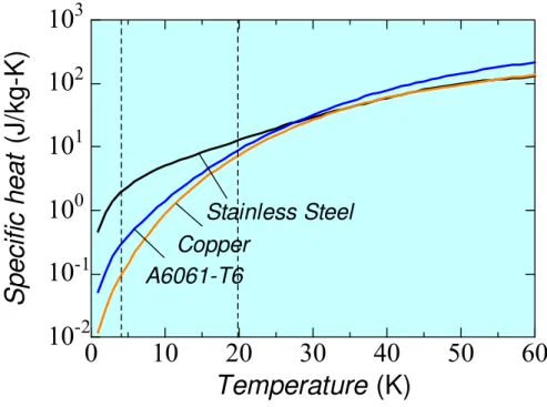
As discussed above, HTS conductors, especially YBCO, can be used at elevated temperatures of ~ 20 K or higher in high magnetic fields. The specific heats of the materials are much higher at 20 K compared to them at 4 K. Figure 1.17 shows the specific heat of typical superconducting magnet materials as a function of temperature [1.50]. It clearly indicates that the specific heats are 10 – 100 times larger at 20 K compared to those at 4 K. This increased specific heat at 20 K makes HTS conductors invulnerable to thermal disturbances coming from wire motions, epoxy crackings, etc. in superconducting magnet and therefore improves the stability of HTS magnets. This is
0 5 10 15 20 25 30
10
110
210
310
410
5Magnetic Field (T)
Cr it ic al Cur rent Dens it y (A/ m m
2)
YBCO
(20 K) Bi-2212(4.2 K)
Bi-2223
(20 K) NbTi(4.2 K)
(4.2 K)
(4.2 K)
Nb3Al(4.2 K)
Nb3Sn(4.2 K)
another big advantage in HTS conductors, which make HTS magnets almost quench free and promise to provide safe and interruption free operations of a fusion reactor.
Fig. 1.17: Specific heat of typical superconducting magnet materials as a function of temperature. A6061-T6 is an aluminum alloy.
Thermal conductivity
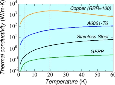
At elevated temperature of ~20 K, the thermal conductivity of materials is also improved. This improved thermal conductivity helps in removing the heat quickly, especially when the magnets are indirect or conduction cooled. Due to the increased stability of HTS conductors at ~20 K, the active cooling may not be required for HTS magnets unlike conventional LTS magnets where magnets are actively cooled by liquid or supercritical helium at ~ 4 K. Figure 1.18 shows the thermal conductivity of some materials as a function of temperature [1.50]. It clearly indicates that the thermal conductivities are 5 – 10 times higher at 20 K compared to those at 4 K.
0 10 20 30 40 50 60
10
-210
-110
010
110
210
3Temperature (K)
S pec if ic heat (J/ k g -K)
Copper A6061-T6
Stainless Steel
Fig. 1.18: Thermal conductivity of the materials as a function of temperature. A6061-T6 is an aluminum alloy.
Refrigeration power
As discussed before, HTS magnets can be operated at ~20 K or higher temperatures and therefore much less refrigeration power is required compared to LTS magnets which are operated at ~ 4 K. Figure 1.19 shows the ideal input power per Watt of refrigeration considering 100% efficient Carnot cycle [1.16]. It clearly indicates that the input power is about 5 times less at 20 K whereas it is about 15 times less at 50 K compared to 4 K. This reduced input power requirement makes a fusion reactor economically more viable as it is operated continuously over a long period of time.
0 10 20 30 40 50 60
10
-210
-110
010
110
210
310
4T her m a l c o nduc ti v it y (W /m -K)
Temperature (K)
Copper (RRR=100)
A6061-T6 Stainless Steel
GFRP
Fig. 1.19: Carnot specific power as a function of refrigeration temperature.
1.6 Proposal of large-current capacity HTS conductors
Owing to several advantages of HTS conductors as discussed above, HTS conductors are promising candidates for future fusion energy reactor magnets [1.51 – 1.54]. Compared to LTS conductors, HTS conductors possess higher stability due to large temperature margin. The typical operating temperature for a HTS conductor magnet may be about 20 K and the temperature margin is supposed to be more than 10 K (typical temperature margin of LTS conductors is ~1 K) in a magnetic field of 13 ~ 20 T. The higher stability of HTS conductors can be exploited in developing a high stability conductor or virtually a quench free conductor suitable for fusion energy reactors. Due to the increased stability of conductors, the reliable and safer operations of fusion energy reactors can be assured and problems related with quench and energy dump can be mitigated.
Unlike LTS conductors, HTS conductors are available only in primitive forms (tape and strand) and no large-current capacity HTS conductor suitable for fusion reactor magnets has been developed yet. Through this thesis research, our objective is to examine the feasibility of a 100 kA-class HTS conductor suitable for fusion energy reactor magnets, especially the DC magnets, such as the helical coils in a heliotron-based fusion reactor or toroidal coils in tokamak-based fusion reactors.
As discussed before, HTS materials are basically ceramic materials and are mostly available in tape forms and thus, it is not easy to twist or transpose many of them to form a large-current capacity conductor. As is also discussed before, transposition is necessary to avoid non-uniform current distribution in conductors. However, opposite to this idea, we propose a large-current capacity HTS conductor with simple stacking of HTS tapes. This idea is rather bold as there has been no such conductor so far without any transposition of wires. It is quite natural to have non-uniform current distribution in such kind of conductors due to the inductance mismatching. Therefore, our main focus during this research is on the stability of large-current capacity HTS conductors and the effect of non-uniform current distribution on the stability of the HTS conductor with simple stacking of tapes.
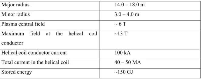
During this research, we developed and studied 10 kA-class (at 20 K and 8 T) YBCO and Bi-2223/Ag HTS conductors by simply stacking them inside copper sheaths. In this thesis, we design and propose 100 kA-class (20 K, 13 T) HTS conductors for the LHD-type force-free helical reactor (FFHR). The major design parameters of FFHR machine are given in Table 1.3 [1.55]. A bird eye view of FFHR is shown in Fig. 1.20.
The major specifications of the proposed 100 kA HTS conductor are shown in Table 1.4 and the cross-sectional view of the conductor is shown in Fig. 1.21.
Table 1.3: Major parameters of the LHD type helical reactor FFHR
Major radius 14.0 – 18.0 m
Minor radius 3.0 – 4.0 m
Plasma central field ~ 6 T
Maximum field at the helical coil conductor
~13 T
Helical coil conductor current 100 kA Total current in the helical coil 40 – 50 MA
Stored energy ~150 GJ
Table 1.4: Major Specifications of the proposed 100 kA HTS conductor
Superconductor YBCO
Operating temperature 20 – 25 K
Maximum field on the conductor 13.25 T
Critical current of HTS tape 100 A per mm width (25 K, 13 T)
Operating current 100 kA
Current density ~ 40 A/mm2
Copper to HTS ratio 7
Cooling method Indirect cooled
Fig. 1.20: Bird’s-eye view of the LHD-type force-free helical reactor FFHR [1.55].
(a) (b)
Fig. 1.21: (a) Cross-sectional and (b) 3-D views of the 100 kA HTS conductor proposed for the helical coils of FFHR.
Chapter 2
Cryogenic stability of cable-in-conduit
conductors (CICC)
As introduced in Chapter 1, the stability of a large-current capacity conductor is affected by non-uniform current distribution (NUCD), especially in insulated strand conductors where the current redistribution is not easy. The proposed HTS conductor with simple stacking of the HTS tapes without any insulation between them will also be subjected to non-uniform current distribution due to the inductance mismatching. Though the current redistribution among the HTS tapes might be easier due to the absence of any insulation, it is still an important task to examine the stability of a HTS conductor with non-uniform current distribution. Before developing and examining the stability with non-uniform current distribution of HTS conductors, it was thought to be a good idea to examine the stability of presently available with bare strands full-scale LTS conductor with controlled non-uniform current distribution. Secondly, it was also thought that this research might provide some valuable information to some of the ongoing projects such as ITER and JT- 60SA whose magnets are based on LTS conductors. Therefore, the research on the examination of stability of bare strand cable-in-conduit conductors (CICC) with controlled non-uniform current distribution has been carried out. The results of this research activity are discussed in this chapter.
2.1 Stability of a typical CICC
The typical cross-sectional view of a cable-in-conduit conductor (CICC) is shown in Fig. 2.1. Hundreds of superconducting strands, twisted in multiple stages, are housed in a high strength conduit (generally stainless steel). The coolant (usually supercritical helium) flows in the voids between the conduit and superconducting strands. Due to the direct contact of the coolant with each strand increases the stability of the conductor against thermal disturbances. The typical stability margin of a CICC (usually measured in mJ/cm3) as a function of operation current is shown in Fig. 2.2 [2.1]. The stability margin line is divided in two parts: the so-called well-cooled and ill-cooled regions. In the well- cooled region, the stability is higher which is mainly governed by the enthalpy of the coolant whereas it is lower in ill-cooled region where it is mainly governed by the enthalpy of the strands. The operation current dividing these two regions is generally called as limiting current, which can be determined by the following equation [2.2].
cu op c cu
wA T T
I hp
ρ
) (
lim
= − (2.1)
where h, pw, Tc, Top, Acu, ρcu are heat transfer coefficient, wetted perimeter, critical temperature, operation temperature, copper area, and copper resistivity respectively. Generally, limiting current criterion is used to design a cable-in-conduit conductor to ensure high stability of the conductor, which is basically applicable for steady state conditions and assumes the uniform current distribution in the conductor. Usually, the normalized operation current (Iop/Ic) of a CICC in a magnet is ~ 0.4 to ensure high stability [2.1]. Here, Iop and Ic are the operational and critical currents of the conductor.
Fig. 2.1: Schematic cross-sectional view of a typical cable-in-conduit conductor (CICC).
Fig. 2.2: Stability margin of a typical CICC as a function of normalized operation current (Iop/Ic). Ic is the critical current of the conductor. The so-called well-cooled and ill-cooled regions are indicated along with the limiting current [2.1].
2.2 Experimental set-up for the stability measurement
of a CICC with NUCD
As discussed before, stability of bare strands CICC was measured with non-uniform current distribution in the conductor. This section describes the details of the experimental setup and measurement method.
2.2.1 Conductor specifications
The CICC for Steady State Tokamak (SST-1) magnets in India was used for preparing the short samples for this research [2.3]. The major specifications of the conductor are shown in Table 2.1 [2.4]. A cross-sectional view of the conductor and the schematic of different twisting stages of the conductor are shown in Fig. 2.3.
Table 2.1: Major specifications of the SST-1 CICC Strands
Diameter (mm) 0.86 ± 0.005
Copper / SC ratio 4.88
Surface Condition Bare
Critical Current, Ic, at 5 T (A) ≥ 272
RRR ≥ 100
Index n ≥ 25
Cabling
Cabling Scheme 3 × 3 × 3 × 5
Twist Pitch Lengths (mm) 40, 75, 130,
290 Conduit
Outer Dimensions (mm) 14.8 × 14.8
Thickness (mm) 1.5
Ic at 5 T (kA) ≥ 35
Void fraction (%) 40 ± 2
(a)
(b)
Fig. 2.3: (a) Cross-sectional view of the SST-1 CICC [2.3]; (b) schematic of different twisting stages in the SST-1 CICC.
2.2.2 Experimental sample
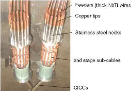
An experimental set-up with a sophisticated current feeder system was prepared to study the influence of NUCD on the stability of bare strands NbTi/Cu CICC for SST-1. This project was named INNOCENTS (INstabilities due to NOn-uniform Current distribution experimENTS). The schematic of the experimental set-up is shown in Fig. 2.4. The conductor was wound non-inductively in two turns with a radius of ~180 mm. The CICC has 135 strands of a diameter 0.86 mm twisted in 3 × 3 × 3 × 5 pattern with 40, 75, 130, and 290 mm twist pitch lengths as shown in Fig. 2.3b. The last two twisting stages of the CICC were opened up into 15 sub-cables of 9 strands each at both ends of the sample winding. In a terminal box, these 15 sub-cables were individually soldered with 15 thick high-current capacity NbTi/Cu wires (as shown in Fig. 2.5), which were finally connected with current leads as shown in Fig. 2.6. The feeders were arranged in one layer in the terminal block to avoid any non-uniform current distribution caused by the terminal joint itself.
Fig. 2.4: Schematic view of the experimental setup for stability measurement of the CICC with non-uniform current distribution.
Fig. 2.5: Connection of 15 numbers of 2nd stage sub-cables with 15 thick high-current capacity NbTi/Cu wires (feeders) in terminal boxes.
Fig. 2.6: Connection of 15 NbTi/Cu feeders with a terminal block, which connects the current lead to supply the current into the sample. The feeders are arranged in one layer to avoid any non-uniformity in the current distribution from the terminal itself.
Resistive heaters for artificial introduction of NUCD
Thin film heaters were mounted on the thick NbTi/Cu feeders individually to initiate normal-zones in them and thereby establishing a NUCD in the CICC as indicated in the Fig. 2.4. These NbTi/Cu wires were thermally isolated from the testing area and therefore did not affect the stability measurements. The arrangement of thin film heaters over feeders is shown in Fig. 2.7. By turning on the selective heaters, different kinds of controlled NUCD patterns can be established in the conductor. Figure 2.8 shows some examples of NUCD patterns, which were established before the stability measurements. Here, Step-0, Step-1, Step-3, and Step-6 correspond to 0, 20, 47, and 67% strands of the whole conductor, which were initially prevented to carry any current.
Fig. 2.7: Arrangement of thin film resistive heaters on the NbTi/Cu feeders to introduce different kinds of NUCD patterns in a controlled way.
Fig. 2.8: Different NUCD patterns established by using thin film resistive heaters. Step-0 shows the uniform current distribution in the conductor. The current in white-portioned sub-cables was prevented by resistive heaters.
Current distribution measurement system (CDMS)
From terminal boxes, the feeder lines go through the current distribution measurement system (CDMS). In CDMS, the feeder lines are arranged equidistantly around a GFRP hollow pipe. Inside this hollow pipe, rotating Hall sensors were arranged. These hall sensors rotate 360 degrees and measure the magnetic field generated by the feeder lines.
Fig. 2.9: Arrangement of feeder lines over GFRP hollow pipe of the current distribution measurement system (CDMS). The rotating Hall sensors were inside the hollow pipe to measure the field distribution according to individual current distribution pattern.
According to individual current distribution pattern as shown in Fig. 2.8, the field distribution is different which is measured by rotating Hall sensors and hence the current distribution is measured in the conductor. Figure 2.9 shows the arrangement of feeder lines over CDMS.
Induction heaters for stability margin measurements
Induction heaters were wound around each turn of the winding to initiate normal-zones. Induction heater consisted of 180 turns of insulated copper wire of about 1 mm diameter. During the experiments, after establishing the desired current distribution, the induction heater was turned on by discharging a capacitor to initiate a normal-zone in the conductor.
Fig. 2.10: Induction heaters wound over both turns of the CICC.
Figure 2.10 shows the induction heater wound over the CICC. The length of the induction heater was about 30 mm.
Cooling scheme
The CICC sample was cooled by supplying the pure He gas from outside through the counter flow and single pipe heat exchangers, which were immersed in liquid helium.
The pure He gas was supplied at 0.4 MPa into the sample which then flows through the heat exchangers and then condenses into the supercritical helium at 0.4 MPa and 4.2 K. The experiments were carried out at stagnant helium conditions and therefore outlet of helium line at room temperature was kept closed using a safety release valve. Figure 2.11 shows the single pipe heat exchanger used in the experiment.
Fig. 2.11: Single pipe heat exchanger to condensate the pure helium gas.
Diagnostics
Lots of diagnostic sensors were installed which include Cernox temperature sensors, Hall sensors, pick-up coils, pressure sensor, flow meter, and voltage taps. To insure appropriate temperature conditions during experiments, Cernox temperature sensors were installed in the terminal boxes and at the joint location as shown in Fig. 2.4. As discussed above, rotating Hall sensors were installed to measure current distribution in the
![Fig. 1.2: Strain dependence of Nb 3 Sn and Nb 3 Al on critical currents [1.3].](https://thumb-ap.123doks.com/thumbv2/123deta/6157180.103585/15.918.298.656.110.464/fig-strain-dependence-nb-sn-nb-critical-currents.webp)

![Fig. 1.14: Load line of DPC single coil charge. Solid circles show the quench points [1.42]](https://thumb-ap.123doks.com/thumbv2/123deta/6157180.103585/32.918.298.667.111.485/fig-load-single-charge-solid-circles-quench-points.webp)
![Fig. 2.3: (a) Cross-sectional view of the SST-1 CICC [2.3]; (b) schematic of different twisting stages in the SST-1 CICC](https://thumb-ap.123doks.com/thumbv2/123deta/6157180.103585/45.918.179.787.140.486/cross-sectional-cicc-schematic-different-twisting-stages-cicc.webp)