Synthesis, Properties and Catalytic Activities
for CO
2Reduction of Porphyrins and
Porphyrin Complexes Bearing
π -Conjugated Substituents
OKABE YUKI
Doctor of Philosophy
Department of Structural Molecular Science
School of Physical Sciences
SOKENDAI (The Graduate University for
Advanced Studies)
Synthesis, Properties and Catalytic Activities for CO
2Reduction of Porphyrins and Porphyrin Complexes
Bearing π-Conjugated Substituents
Okabe, Yuki
SOKENDAI (The Graduate University for Advanced Studies)
School of Physical Sciences
Department of Structural Molecular Science
Contents
General Introduction
1
Chapter 1
Synthesis, crystal structures and physical properties of porphyrins and porphyrin complexes
25
Chapter 2
Synthesis and CO2reduction activities of π-expanded/extended iron porphyrin complexes 75
Chapter 3
Construction of framework structure based on metalloporphyrin catalysts via intermolecular non-covalent interaction between pyrene units
115
Acknowledgements
146
List of Publications
148
1
General Introduction
CO2 Reduction
The development of sustainable energy conversion system is strongly required in recent years due to the exhaustion of fossil fuels and environmental problems in the world. In nature, efficient sustainable energy conversion is achieved by photosynthetic reactions. In natural photosynthetic reactions, carbon dioxide (CO2) is converted into chemical energy (glucose) by utilizing solar energy. In this context, the development of artificial photosynthesis,1, 2 which mimics the natural photosynthetic reaction, is an attractive research subject. As well as natural photosynthesis, clean chemical energy can be obtained from the abundant source on the earth in artificial photosynthesis. The catalytic reduction of CO2 is a representative example of artificial photosynthetic reactions. As shown in Scheme 1, CO2 can be reduced to various kinds of chemical fuels such as carbon monoxide (CO), formic acid, formaldehyde, methanol and methane. These reactions are advantageous because the decrease in the amount of CO2 in the atmosphere and the generation of clean chemical energy source can be achieved at the same time.3 In particular, CO is greatly useful carbon source which is utilized in the synthesis of liquid fuels kind of liquid hydrocarbons by the Fischer-Tropsch process.4 Therefore, the development of catalytic system which can convert CO2 to CO is a crucially important research target.
2
Scheme 1. CO2 reduction reactions to produce chemical fuels.
3 Porphyrin Derivatives
Porphyrin is an aromatic macrocyclic molecule which have large π-electronic system. The synthesis and physical properties of porphyrin and its derivatives have been widely studied from the end of the 19th century.5 These molecules have following four features which are potentially important for the catalytic CO2 reduction (Figure 1).
At first, porphyrin derivatives have a metal binding site at the center of the macrocycle (Figure 1a). Porphyrin derivatives which have a metal ion at the binding site are called metalloporphyrins, and are known to serve as catalysts for several catalytic reactions. In natural systems, an oxidoreductase superfamily called cytochrome P450, which exist in livers of animals, includes Heme, a kind of iron porphyrins complex, in its structure. This class of enzymes can catalyze various oxidation reactions, and metal centers of Heme function as active centers in these reactions.6 Metalloporphyrins are used as catalysts in artificial systems as well, and the many kinds of organic reactions including hydroxylation, amination, and epoxidation are catalyzed by metalloporphyrins with variety of metal ions.7
Second, porphyrin derivatives have high light-harvesting ability (Figure 1b). Chlorophyll, which is green pigments found in cyanobacteria and the chloroplasts of algae and plants, contains a porphyrin skeleton and function as a light harvesting unit in the natural photosynthetic reaction. In artificial systems, light-harvesting ability of porphyrin derivatives are also widely used. For instance, zinc porphyrin derivatives are employed as photosensitizers in several model compounds to study photoinduced electron transfer processes.8
Third feature is redox flexibility (Figure 1c). Porphyrins exhibit redox activity, and are possible to proceed reversible multi-redox reaction utilizing π electrons highly delocalized on the macrocycle.9 Additionally, the introduction of appropriate substituents to their meso-positions, sp3 carbons bridged by pyrroles, enables the further control over the redox properties. The modification of the meso-positions is synthetically straightforward and possible to install not only electron-donating and -withdrawing group but also redox active substituents like ferrocenyl10 and quinolyl group.11
Fourth feature is that porphyrin macrocycle bear highly symmetric and rigid π- planar structure (Figure 1d). π-Planes of porphyrins often exhibit intermolecular
4
interaction such π-π and CH-π interaction and form assembled structures both in solution12 and in the solid phase.13 Such assembled structures usually display hydrophobicity due to the large π-planes of porphyrins and are expected to have high affinity with non-polar CO2 molecules.
5
Figure 1. Four important features of porphyrin derivatives for CO2 reduction.
6 Metalloporphyrin-Catalyzed CO2 Reduction
As described in the previous section, porphyrin can form metal complexes, metalloporphyrins, and the metal centers of metalloporphyrins can serve as catalytic centers for various reactions (Figure 1a). Inspired by the feature, the catalytic activity of metalloporphyrin for CO2 reduction has been studied. In 1988, Savéant et al. reported the electrochemical reduction of CO2 reduction catalyzed by an iron tetraphenylporphyrin complex (Fe-TPP, Figure 2a) for the first time.14 In this catalytic reaction, CO was obtained as a major product. The proposed catalytic cycle of Fe-TPP is shown in Scheme 2.15 In this mechanism, Fe(0) species formed by the three electron reduction of Fe-TPP can serve as an active species for the reaction, which indicates that the high redox flexibility of the porphyrin derivative (Figure 1c) is essential to promote the reaction. It should be also noted that the existence of Lewis acids or Brønsted acids can enhance the catalytic activity of Fe-TPP.15, 16
After the discovery of catalytic activity of Fe-TPP, the development of iron porphyrin-based catalysts for electrochemical reduction of CO2 has begun to explore and various kinds of iron-porphyrins for electrocatalysts for CO2 reduction have been reported up to date17 (for representative examples, see Figure 2a). Savéant et al. found that the introduction of proton reservoir sites into the porphyrin moiety of Fe-TPP can improve the catalytic activity.15, 16 More recently, it is reported that an unsymmetrical iron porphyrin complex bearing both 2,6-dihydroxyphenyl groups as proton reservoir sites and 2,3,4,5,6-pentafluorophenyl groups as withdrawing groups exhibits superior activity. It is also found that a water soluble iron porphyrin bearing trimethylammonium groups able to convert CO2 into CO with a little amount of H2 under neutral pH conditions.18 Sun et al reported the effect of the position of methoxycarbonyl group introduced to the phenyl moieties on the catalytic activity.19
It is noteworthy that iron porphyrin complexes undergoes photocatalytic CO2
reduction and the examples of iron porphyrin-based photocatalysts are shown in Figure 2b.20 Initially, Neta et al. reported that photolysis of Fe-TPP in DMF solutions containing 5% of triethylamine as a sacrificial electron donor resulted in the formation of CO.21 The turnover number of the reaction was approximately 40. In these reactions, Fe- TPP functions not only as a catalyst but also as a photo absorbing unit utilizing its high
7
light harvesting ability (Figures 1b). The authors also investigated the photoreduction of CO2 in aqueous media using tetrakis(N-methyl-2-pyridyl)porphyrin iron(III) chloride as a catalyst.
The cobalt porphyrin complexes are also known to catalyze CO2 reduction both under electrochemical and photochemical conditions (Figures 2c, d). The cobalt complex of tetraphenylporphyrin, Co-TPP and its derivative bearing trifluoromethyl groups are known to undergo electrocatalytic CO2 reduction.22 Photocatalytic activity of Co-TPP was also examined and it is found that the addition of p-terphenyl as a photosensitizer or trimethylamine as sacrificial electron donor can enhance the catalytic activity of the system.23
8
Figure 2. Examples of (a) iron porphyrin complexes catalysts for electrochemical CO2
reduction (b) iron porphyrin complexes catalysts for photochemical CO2 reduction (c) cobalt porphyrin complexes catalysts for electrochemical CO2 reduction (d) cobalt porphyrin complexes catalysts for photochemical CO2 reduction.
9
Scheme 2. Proposed mechanism of catalytic CO2 reduction by Fe-TPP.
10
CO2 Adsorption in Porphyrin-based Framework
In the atmospheric condition, the concentration of CO2 is quite low. However, it is very difficult for the currently developed catalysts for CO2 reduction to proceed the reaction under the ambient condition and most of the system requires the highly concentrated CO2 gas for the reaction. Therefore, the development of the system which can accumulate CO2 gas nearby catalytic centers is an important research target.
Metal organic frameworks (MOF)24 and covalent organic frameworks (COF)25 are an intriguing class of materials for the accumulation of CO2. MOFs and COFs have a highly ordered porous network structure constructed by the self-assembly of organic linkers and metal ions (MOFs) or organic linkers (COFs). It is also noteworthy that the size of and the hydrophilicity/ hydrophobicity of pores can finely be tuned by changing the molecular structure of organic linkers which construct the framework, which results in the selective accommodation of gas molecules.26 Additionally, the functional moieties such as catalytic centers and sensing sites can easily be integrated into the frameworks.27 These features of MOFs and COFs differentiate them from the conventional porous materials such as activated carbon and zeolites.
Porphyrin derivatives are known to serve as building units for porous materials due to their highly symmetric and rigid structures (Figure 1d). In 1994, Robson et al., reported that two kinds of copper(II) porphyrin complexes can form the porous framework via non-covalent interaction between complexes. After the discovery of MOFs and COFs, porphyrin derivatives have started to be used as organic linkers and various kinds of structures are reported so far.28
In these reports, the several frameworks are found to be capable to adsorb CO2
gas in their pores.29 Ma et al. have constructed a MOF composed of cobalt ions and tetrakis(3,5-dicarboxyphenyl)porphine cobalt(II) (Co(II)tdcpp) as an organic linker, {[Co(II)3(OH)(H2O)]4(Co(II)tdcpp)3} (MMPF-2, Figure 3a)).30 The authors concluded that high density of the coordinatively unsaturated cobalt atoms within the porphyrin macrocycles contributed to the excellent CO2 adsorption properties of the MOF. Jiang et al. prepared imine-linked COFs bearing 5,10,15,20-tetraphenylporphyrin moiety (Figure 3b).31 They systematically controlled the properties of pore surface by introducing diverse functional groups with controllable loading contents via click reaction.
11
More recently, Yaghi et al. has succeeded in developing a COF that can catalyse CO2 reduction using cobalt porphyrin complexes as organic linkers (Figure 4).32 The COF developed by the group exhibited 26 times higher catalytic activity for CO2 reduction in aqueous media compared with the corresponding discrete system. They also found that the expansion of pore size resulted in the higher activity. These reports strongly suggest that the utilization of porous framework can be a powerful tool to develop a highly efficient catalytic system for CO2 reduction.
12
Figure 3. (a) (left) Three cobalt porphyrins located in the “face-to-face” configuration in MMPF-2; (right) space filling model of three types of channels in MMPF-2 viewed from the c direction. Reproduced with permission from Ma et al.30 (b) A Schematic illustration of pore surface engineering of imine-linked COFs with various functional groups via click reactions. Reproduced with permission from Jiang et al.31
13
Figure 4. Design and synthesis of metalloporphyrin-derived 2D covalent organic frameworks. Reproduced with permission from Yaghi et al.32
14 The Aim of This Thesis
Metalloporphyrin complexes can serve as catalysts CO2 reduction to generate CO. However, it is still difficult to perform the catalytic reaction with the low concentration of CO2 as the atmospheric condition (0.04 %). Therefore, it is necessary for the highly effective CO2 conversion system to develop novel catalytic systems, in which the reaction can proceed under quite low partial pressure of CO2 gas. To achieve such a goal, the introduction of reaction field to accumulate CO2 molecules nearby catalytic centers can potentially be interesting and attractive research target.
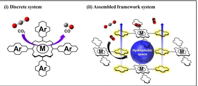
In this thesis, I aimed to construct novel metalloporphyrin-based catalytic systems with reaction fields. I employed two approaches; (i) a discrete system and (ii) an assembled framework system (Figure 5). Both systems are designed to create hydrophobic reaction field close to the metal centers of porphyrin complexes because non-polar CO2 molecules are known to be accumulated in such a field. The installation of hydrophobic field is expected to be achieved by introducing substituents with large π- plane to porphyrin moieties. This study investigates the effect of the introduction of π- conjugated substituents into metalloporphyrin complex on their physical properties. The study can give some knowledge about (i) design and synthesis of porphyrin molecules which is able to form the hydrophobic space (ii) the effect of the hydrophobic space on the catalytic activity of the complex, and (iii) the substituents advantageous for the construction of a high ordered molecular assembly.
15
Figure 5. Schematic illustration of the targeted catalytic system (i) discrete system and (ii) assembled framework system.
16 Survey of This Thesis
Chapter 1 describes the syntheses, crystal structures and physical properties of free-base porphyrins and porphyrin complexes bearing various kinds of substituents at the meso-positions of porphyrin moiety. The synthetic procedures were successfully established for free-base porphyrins with electron-donating (H-TMP), -withdrawing (H- EDB), π-conjugated (H-PEPy and H-PA) and redox active (H-FcN) substituents (Figure 6) and metal complexes bearing the synthesized free-base porphyrins as ligands. The electronic states of the obtained compounds were investigated by UV-vis absorption spectroscopy, electrochemical measurement and transient absorption spectroscopy. Additionally, some crystal structures of free-base porphyrins were also reported, and the intermolecular interactions in each crystal packing were investigated.
Figure 6. Molecular structures of the porphyrin derivatives investigated in chapter 1.
17
Chapter 2 describes the syntheses and the spectroscopic and electrochemical properties of iron porphyrin complexes with π-conjugated substituents at the meso- position (Figure 7). Three novel iron complexes, (5,10,15,20-tetrakis(pyren-1- yl)porphyrinato iron(III) chloride (Fe-Py), (5,10,15,20-tetrakis((1,1’-biphenyl)-4- yl)porphyrinato iron(III) chloride (Fe-PPh), and (5,10,15,20-tetrakis(4-(pyren-1- yl)phenyl)porphyrinato iron(III) chloride (Fe-PPy), were synthesized by the reaction of the corresponding free-base porphyrins 5,10,15,20-tetrakis(pyren-1-yl)porphyrin (H-Py), 5,10,15,20-tetrakis((1,1’-biphenyl)-4-yl)porphyrin (H-PPh), and 5,10,15,20-tetrakis(4- (pyren-1-yl)phenyl)porphyrin (H-PPy) with iron(II) chloride tetrahydrate in DMF or N- methyl-2-pyrrolidone (NMP) and were characterized by elemental analyses and UV-vis absorption spectroscopy.
The electrochemical analyses of the complexes under an Ar atmosphere indicated that the introduction of the π-conjugated substituents rarely affects the electronic structures and redox properties of the iron porphyrin complexes. However, the electrochemical studies under CO2 revealed that the catalytic activity of Fe-Py for CO2
reduction was found to be much higher than that of 5,10,15,20- tetrakis(phenyl)porphyrinato iron(III) chloride (Fe-Ph). These results indicate that the introduction of large π-conjugated substituents directly to the meso-positions of a porphyrin moiety could provide a hydrophobic space suitable for the accumulation of CO2 molecules, which resulted in the superior catalytic activity of the complex.
18
Figure 7. Chemical structures of the porphyrin derivatives investigated in chapter 2.
19
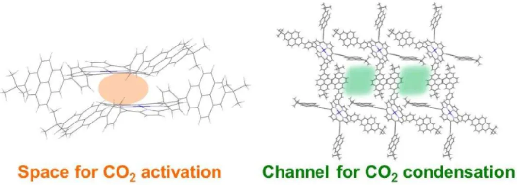
Chapter 3 describes the synthesis, physical properties and crystal structure of porphyrin derivatives for the construction of framework structure with hydrophobic channels. A novel free-base porphyrin, 5,10,15,20-tetrakis(4-(7-(tert-butyl)pyren-2- yl)phenyl)porphyrin (H-BPPy), which possesses four pyrenylphenyl moieties at the meso-positions of a porphyrin ring, were newly designed. The pyrene units installed in this molecules are known to exhibit both face-to-face (π-π) interaction and face-to-edge (CH-π) interaction and easily form the relatively strong assembled structure due to their planar polyaromatic feature. Furthermore, H-BPPy has four-fold symmetry and high planarity, which are advantageous for the construction of a highly ordered structure. Therefore, it is expected that the robust framework structure with hydrophobic pores are constructed by the self-assembly of the H-BPPy based metal complexes at room temperature, which will lead to the development of a novel catalytic system for CO2
reduction.
The synthesis of H-BPPy was accomplished by the condensation reaction of pyrrole with the corresponding aldehyde derivative and the subsequent oxidation by 2,3- dichloro-5,6-dicyano-p-benzoquinone (DDQ). H-BPPy was further reacted with cobalt ( ) acetate tetrahydrate under microwave heating condition and the corresponding cobalt porphyrin complex, Co-BPPy, was successfully obtained. The electrochemical studies of Co-BPPy under a CO2 atmosphere revealed the increase of an irreversible current, which implies the catalytic activity of Co-BPPy for CO2 reduction. Finally, the construction of framework structure via the self-assemble of Co-BPPy was examined. Co-BPPy exhibited high solubility in various organic solvents thanks to the tert-butyl moiety introduced at the 7-position of the pyrene unit, and the single crystals were obtained the slow diffusion of hexane to the THF solution of Co-BPPy. The structural analysis of the obtained single crystal revealed that porous structure with the pore entrance size of 9.03
× 8.64 Å2 was formed via the CH-π interaction between the pyrene units. These pores are expected to function as channels to accumulate CO2 molecules because the pores should exhibit hydrophobic nature surrounded by aromatic ring and the size of pores is large enough to accommodate CO2 (Figure 8).
20
Figure 8. Crystal structures of the framework developed in the study described in chapter 3.
21
References
1. (a) S. W. Gersten, G. J. Samuels, T. J. Meyer, J. Am. Chem. Soc., 1982, 104, 4029. (b) T. Wada, K. Tsuge, K. Tanaka, Angew. Chem. Int. Ed., 2000, 39, 1479. (c) S. Masaoka, K. Sakai, Chem. Lett., 2009, 38, 182. (d) M. Okamura, M. Kondo, R. Kuga, Y. Kurashige, T. Yanai, S. Hayami, V. K. K. Praneeth, M. Yoshida, K. Yoneda, S. Kawata, S. Masaoka, Nature, 2016, 530, 465.
2. (a) D. V. Yandulov, R. R. Schrock, Science, 2003, 301, 76. (b) K. Arashiba, Y. Miyake, Y. Nishibayashi, Nature Chemistry, 2011, 3, 120. (c) J. S. Anderson, J. Rittle, J. C. Peters, Nature, 2013, 501, 84. (d) S. Kuriyama, K. Arashiba, K. Nakajima, Y. Matsuo, H. Tanaka, K. Ishii, K. Yoshizawa, Y. Nishibayashi, Nature Communications, 2016, 7, 12181.
3. N. S. Lewis, D. G. Nocera, Proc. Natl. Acad. Sci. U.S.A., 2006, 103, 15729.
4. (a) H. Schulz, Appl. Catal. A-Gen., 1999, 186, 3. (b) A. Y. Khodakov, W. Chu, P. Fongarland, Chem. Rev., 2007, 107, 1692. (c) E. van Steen, M. Claeys, Chem. Eng. Technol., 2008, 31, 655.
5. (a) J. E. Ranking, G. L. Pardington, The Lancet, 1890, 136, 607. (b) P. Rothemund, J. Am. Chem. Soc., 1939, 61, 2912. (c) P. Rothemund, A. R. Menotti, J. Am. Chem. Soc., 1941, 63, 267. (d) S. Aronoff, M. Calvin, J. Org. Chem., 1943, 8, 205. (e) R. H. Ball, G. D. Dorough, M. Calvin, J. Am. Chem. Soc., 1946, 68, 2278.
6. I. G. Denisov, T. M. Makris, S. G. Sligar, I. Schlichting, Chem. Rev., 2005, 105, 2253. 7. (a) J. P. Collman, X. Zhang, V. J. Lee, E. S. Uffelman, J. I. Brauman, Science, 1993, 261, 1404. (b) C-M. Che, V. K-Y. Lo, C-Y. Zhou, J-S. Huang, Chem. Soc. Rev., 2011, 40, 1950.
8. (a) D. Kuciauskas, P. A. Liddell, S. Lin, T. E. Johnson, S. J. Weghorn, J. S. Lindsey, A. L. Moore, T. A. Moore, D. Gust, J. Am. Chem. Soc., 1999, 121, 8604. (b) D. Kim, A. Osuka, J. Phys. Chem. A, 2003, 107, 8791. (c) Y. Nakamura, N. Aratani, A. Osuka, Chem. Soc. Rev. 2007, 36, 831. (d) G. Kodis, P. A. Liddell, L. de la Garza, P. C. Clausen, J. S. Lindsey, A. L. Moore, T. A. Moore, D. Gust. J. Phys. Chem. A, 2002, 106, 2036. (e) H. Imahori, Y. Sekiguchi, Y. Kashiwagi, T. Sato, Y. Araki, O. Ito, H. Yamada, S. Fukuzumi, Chem. Eur. J., 2004, 10, 3184. (f) H. Imahori, T. Umeyama, S. Ito, Acc. Chem. Res., 2009, 42, 1809. (g) A. Yella, H-W. Lee, H. N. Tsao, C. Yi, A. K. Chandiran, Md. K. Nazeeruddin, E. W-G. Diau, C-Y Yeh, S. M. Zakeeruddin, M. Grätzel, Science, 2011, 334, 629.
9. T. Dhanasekaran, J. Grodkowski, P. Neta, P. Hambright, E. Fujita, J. Phys. Chem. A, 1999, 103, 7742.
22
10. (a) H. Imahori, D. M. Guldi, K. Tamaki, Y. Yoshida, C. Luo, Y. Sakata, S. Fukuzumi, J. Am. Chem. Soc., 2001, 123, 6617. (b) S. J. Dammer, P. V. Solntsev, J. R. Sabin, V. N. Nemykin, Inorg. Chem., 2013, 52, 9496. (c) A. Vecchi, P. Galloni, B. Floris, S. V. Dudkin, V. N. Nemykin, Coord. Chem. Rev. 2015, 291, 95.
11. (a) H. Grennberg, S. Faizon, J-E. Bäckvall, Angaw. Chem. Int. Ed. Engl., 1993, 32, 263. (b) M. Schreiber, C. Fuchs, R. Scholz, J. Lumin., 1998, 76, 482. (c) A. Wiehe, M. O Senge, A. Schäfer, M. Speck, S. Tannert, H. Kurreck, B. Röder, Tetrahedron, 2001, 57, 1008λ. (d) F. D’Souza, G. R. Deviprasad, J. Org. Chem., 2001, 66, 4601. 12. (a) M. Shirakawa, S. Kawano, N. Fujita, K. Sada, S. Shinkai, J. Org. Chem., 2003,
68, 5037. (b) T. Hasobe, S. Fukuzumi, P. V. Kamat, J. Am. Chem. Soc., 2005, 127, 11884.
13. (a) K-J. Lin, Angew. Chem. Int. Ed., 1999, 38, 2730. (b) I. Goldberg, Chem. Commun., 2005, 1243. (c) H. Liu, J. Xu, Y. Li, Y. Li, Acc. Chem. Res., 2010, 43, 1496.
14. M. Hammouche, D. Lexa, J-M. Savéant, M. Momenteau, J. Electroanal. Chem. Interfacial Electrochem., 1988, 249, 347.
15. C. Costentin, S. Drouet, G. Passard, M. Robert, J-M. Savéant, J. Am. Chem. Soc., 2013, 135, 9023.
16. (a) I. Bhugun, D. Lexa, J-M. Savéant, J. Am. Chem. Soc., 1994, 116, 5015, (b) I. Bhugun, D. Lexa, J-M. Savéant, J. Am. Chem. Soc., 1996, 118, 1769, (c) I. Bhugun, D. Lexa, J-M. Savéant, J. Phys. Chem., 1996, 100, 19981, (d) C. Costentin, S. Drouet, M. Robert, J-M. Savéant, Science, 2012, 338, 90.
17. (a) C. Costentin, G. Passard, M. Robert, J-M. Savéant, Proc. Natl. Acad. Sci. U.S.A., 2014, 111, 14990. (b) H-Z. Zhao, Y-Y. Chang, C. Liu, J. Solid. State. Electr., 2013, 17, 1657. (c) K. Alenezi, S. K. Ibrahim, P. Li, C. J. Pickett, Chem. Eur. J., 2013, 19, 13522. (d) E. A. Mohamed, Z. N. Zaharan, Y. Naruta, Chem. Commun., 2015, 51, 16900. (e) R. B. Ambre, Q. Daniel, T. Fan, H. Chen, B. Zhang, L. Wang, M. S. G. Ahlquist, L. Duan, L. Sun, Chem. Commun., 2016, 52, 14478. (f) J. Choi, T. M. Benedetti, R. Jalili, A. Walker, G. G. Wallace, D. L. Officer, Chem. Eur. J., 2016, 22, 14158.
18. C. Costentin, M. Robert, J-M. Savéant, A. Tatin, Proc. Natl. Acad. Sci. U. S. A., 2015, 112, 6882.
19. L. Sun, Chem. Commun., 2016, 52, 14478.
20. A. J. Morria, G. J. Meyer, E. Fujita, Acc. Chem. Res., 2009, 42, 1983.
21. J. Grodkowski, D. Behar, P. Neta, P. Hambright, J. Phys. Chem. A, 1997, 101, 248. 22. (a) D. Behar, T. Dhanasekaran, P. Neta, C. M. Hosten, D. Ejeh, P Hambright, E.
Fujita, J. Phys. Chem. A, 1998, 102, 2870. (b) D. Quezada, J. Honores, M. Garcia, F.
23
Armijo, M. Isaacs, New J. Chem., 2014, 38, 3606. (c) K. Takahashi, K. Hiratsuka, H. Sasaki, S. Toshima, Chem. lett., 1979, 305. (d) T. Atoguchi, A. Aramata, A. Kazusaka, M. Enyo, J. Chem. Soc., Chem. Commun., 1991, 156.
23. T. Dhanasekaran, J. Grodkowski, P. Neta, P. Hambright, E. Fujita, J. Phys. Chem. A, 1999, 103, 7742.
24. (a) S. Kitagawa, R. Kitaura, S. Noro, Angew. Chem. Int. Ed., 2004, 43, 2334, (b) O. M. Yaghi, M. O’Keeffe, N. W. Ockwig, H. K. Chae, M. Eddaoudi, J. Kim, Nature, 2003, 423, 705.
25. S-Y. Ding, W. Wang, Chem. Soc. Rev., 2013, 42, 548.
26. (a) J. A. Johnson, Q. Lin, L-C. Wu, N. Obaidi, Z. L. Olson, T. C. Reeson, Y-S. Chen, J. Zhang, Chem. Commun., 2013, 49, 2828. (b) W-Y. Gao, Z. Zhang, L. Cash, L. Wojtas, S. Ma, CrystEngComm., 2013, 15, 9320. (c) W-Y. Gao, L. Wojtas, S. Ma, Chem. Commun., 2014, 50, 5316. (d) S. Hamad, N. C. Hernandez, A. Aziz, A. R. Ruiz-Salvador, S. Calero, R. Grau-Crespo, J. Mater. Chem. A, 2015, 3, 23458. (e) A. Modak, M. Pramanik, S. Inagaki, A. Bhaumik, J. Mater. Chem. A, 2014, 2, 11642. 27. (a) N. Kornienko, Y. Zhao, C. S. Kley, C. Zhu, D. Kim, S. Lin, C. J. Chang, O. M.
Yaghi, P. Yang, J. Am. Chem. Soc., 2015, 137, 14129. (b) I. Hod, M. D. Sampson, P. Deria, C. P. Kubiak, O. K. Farha, J. T. Hupp, ACS Catal., 2015, 5, 6302.
28. (a) B. F. Abrahams, B. F. Hoskins, D. M. Michail, R. Robson, Nature, 1994, 369, 727. (b) P. D. W. Boyd, C. A. Reed, Acc. Chem. Res., 2005, 38, 235. (c) K. S. Suslick, P. Bhyrappa, J-H. Chou, M. E. Kosal, S. Nakagaki, D. W. Smithenry, S. R. Wilson, Acc. Chem. Res., 2005, 38, 283. (d) L. Chen, Y. Yang, D. Jiang, J. Am. Chem. Soc., 2010, 132, 9138. (e) S. Wan, F. Gándara, A. Asano, H. Furukawa, A. Saeki, S. K. Dey, L. Liao, M. W. Ambrogio, Y. Y. Botros, X. Duan, S. Seki, J. F. Stoddart, O. M. Yaghi, Chem. Mater., 2011, 23, 4094. (f) A. Fateeva, P. A. Chater, C. P. Ireland, A. A. Tahir, Y. Z. Khimyak, P. V. Wiper, J. R. Darwent, M. J. Rosseinsky, Angew. Chem. Int. Ed., 2012, 51, 744. (g) W. Morris, B. Volosskiy, S. Demir, F. Gándara, P. L. McGrier, H. Furukawa, D. Cascio, J. F. Stoddart, O. M. Yaghi, Inorg. Chem., 2012, 51, 6443. (h) S. Kandambeth, D. B. Shinde, M. K. Panda, B. Lukose, T. Heine, R. Banerjee, Angew. Chem. Int. Ed., 2013, 52, 13052. (i) M. Calik, F. Auras, L. M. Salonen, K. Bader, I. Grill, M. Handloser, D. D. Medina, M. Dogru, F. Löbermann, D. Trauner, A. Hartschuh, T. Bein, J. Am. Chem. Soc., 2014, 136, 17802. (j) Z-S. Wu, L. Chen, J. Liu, K. Parvez, H. Liang, J. Shu, H. Sachdev, R. Graf, X. Feng, K. Müllen, Adv. Mater., 2014, 26, 1450. (k) M. Zhao, S. Ou, C-D. Wu, Acc. Chem. Res., 2014, 47, 1199. (a) Z. Guo, B. Chen, Dalton Trans., 2015, 44, 14574. (b) S. Huh, S-J. Kim, Y. Kim, CrystEngComm., 2016, 18, 345.
24
29. S. Kumar, M. Y. Wani, C. T. Arranja, J. A. e Silva, B. Avula, A. J. F. N. Sobral, J. Mater. Chem. A, 2015, 3, 19615.
30. X-S. Wang, M. Chrzanowski, C. Kim, W-Y. Gao, L. Wojtas, Y-S. Chen, X. P. Zhang, S. Ma, Chem. Commun., 2012, 48, 7173.
31. N. Huang, R. Krishna, D. Jiang, J. Am. Chem. Soc., 2015, 137, 7079.
32. S. Lin, C. S. Diercks, Y-B. Zhang, N. Kornienko, E. M. Nichols, Y. Zhao, A. R. Paris, D. Kim, P. Yang, O. M. Yaghi, C. J. Chang, Science,2015, 349, 6253.
25
Chapter 1
Synthesis, crystal structures and physical properties of
porphyrins and porphyrin complexes
Introduction
Porphyrin and its metal complexes are an intriguing class of molecules that shows rich redox chemistry and unique photophysical properties arising from highly delocalized π system. The first synthesis of a porphyrin derivative was achieved by Rothemund in 1935.1 He reported the synthesis of tetraphenyl porphyrin from pyrrole and benzaldehyde. However, the isolated yield of the target compound was quite low, and this method is not suitable for the practical use. Latterly, Adler et al., discovered the more convenient synthetic procedure to obtain tetraphenyl porphyrin and the yield of the synthetic reaction has dramatically improved.2 However, this method is applicable only for the synthesis of symmetrical tetra-substituted porphyrin derivatives, and the selective synthesis of unsymmetrical porphyrins, which requires the condensation of pyrrole with more than two kinds of aldehyde derivatives, was quite difficult. To overcome such a problem, Lindsey et al., developed an alternative synthetic route.3 In their method, the diluted reaction condition was used to decrease the amount of an undesired side product, polypyorrylmethane, forms upon the condensation step and the formation of the desired porphyrin skelton became thermodynamically favorable. Additionally, they examined the syntheses of several unsymmetrical porphyrin derivatives via stepwise synthetic route, and succeeded in increasing the selectivity of the desired compounds.4 After the discovery of these synthetic methods, the studies on porphyrin derivatives has explosively accelerated, which afforded various kinds of porphyrin-based functional materials.5
This chapter describes the syntheses and physical properties of porphyrins and porphyrin complexes bearing substituents at the meso-positions. I employed electron- donating and withdrawing, π-conjugated and redox active substituents. The synthetic route suitable for each substituents was successfully established. The obtained
26
compounds were studied by UV-vis absorption spectroscopy and electrochemical measurements to clarify the effect of the substituents on the electronic state of the molecules. The crystal structure of two compounds were also reported. The chemical structures of molecules investigated in this chapter is shown in Figure 1.
27
Figure 1. Molecular structure of the porphyrin derivatives investigated in this study.
28
Results and Discussion
Syntheses of Porphyrin Derivatives with Electron-Donating Substituents
The syntheses of a free-base porphyrin bearing four electron-donating substituents, 5,10,15,20-tetrakis(2,4,6-trimethoxyphenyl)porphyrin (H-TMP) and its iron complex, 5,10,15,20-tetrakis(2,4,6-trimethoxyphenyl)porphyrinato iron(III) chloride (Fe-TMP) are shown in Scheme 1. I assume that 2,4,6-trimethoxybenzaldehyde has lower reactivity compared to benzaldehyde due to the electron withdrawing nature of 2,4,6-trimethoxyphenyl group. Therefore, the stepwise synthetic route involving the isolation of the corresponding dipyrromethane derivative was employed. The synthesis of 5-(2,4,6-trimethoxyphenyl)dipyrromethane was performed by reacting 2,4,6- trimethoxybenzaldehyde with an excess amount of pyrrole and the desired compound was obtained in 22% yield. Subsequently, the obtained dipyrromethane was reacted with 2,4,6-trimethoxybenzaldehyde in dichloromethane (DCM), and the further oxidation of the corresponding porphyrinogen using chloranil as an oxidant affords the desired free- base porphyrin, H-TMP, in 38% yield. H-TMP was characterized by 1H NMR spectroscopy.
The synthesis of the iron complex, Fe-TMP, was performed by reacting H-TMP with iron(II) chloride tetrahydrate (6.2 eq.) in dimethyl sulfoxide (DMSO) under reflux condition for 1h. The isolated yield of Fe-TMP was 73%. Fe-TMP was characterized by elemental analysis.
29
Scheme 1. Synthetic routes for H-TMP and Fe-TMP.
30
Synthesis of a Porphyrin Derivative with Electron-Withdrawing Substituents The synthesis of a free-base porphyrin bearing with two electron-withdrawing substituents, trans-5,15-bis(dimesithylboryldurylethynyl)-10,20-bisphenyl porphyrin (H- EDB) is shown in Scheme 2. (4-ethynyl-2,3,5,6-tetramethylphenyl)dimesitylborane (EDDB) was synthesized as follows.6 1,2,4,5-Tetramethylbenzene was brominated using bromine in DCM to afford 1,4-dibrmo-2,3,5,6-tetramethylbenzene in 80% yield. The obtained compound was dehalogenated using n-butyllithium at −β0 °C and the further boronation by dimesitylfluoroborane afforded (4-bromo-2,3,5,6- tetramethylphenyl)bis(2,4,6-trimethylphenyl)borane in 97% yield. The bromo group of the obtained compound was converted to an iodo group via the dehalogenation by t- butyllithium and the subsequent reaction with iodine, and (4-iodo-2,3,5,6- tetramethylphenyl)bis(2,4,6-trimethylphenyl)borane was obtained in 92% yield. Further Sonogashira cross coupling reaction of the compound with trimethylsilylacetylene and the deprotection of the trimethylsilyl affords EDDB.
The synthesis of porphyrin skeleton was performed as follows. First, the reaction of pyrrole and formaldehyde under acidic condition affords dipyrromethane in 49% yield. Dipyrromethane was condensed with benzaldehyde om the presence of triflluoroacetic acid (TFA) and an unsymmetrical porphyrin, 5, 15-bis(phenyl)porphyrin, was obtained (yield:30%). The meso-positions of 5, 15-bis(phenyl)porphyrin was brominated with N- bromosuccinimide (NBS) and trans-5,15-bisbromo-10,20-bisphenyl porphyrin was obtained (yield:95%). Finally, Sonogashira cross coupling of trans-5,15-bisbromo-10,20- bisphenyl porphyrin and EDDB afforded the desired porphyrin derivative, H-EDB, in 43% yield. H-EDB was characterized by 1H NMR spectroscopy.
31
Scheme 2. Synthetic routes for (a) EDDB and (b) H-EDB.
32
Syntheses of Porphyrin Derivatives with π-Conjugated Substituents
The syntheses of free-base porphyrins bearing π-conjugated substituents, and their iron complexes are shown in Schemes 3 and 4. A free-base porphyrin bearing four anthracenylphenyl groups, 5,10,15,20-tetrakis(4-(anthracen-9-yl)phenyl)porphyrin (H- PA), was synthesized using 9-bormoanthracene as a starting substrate. Pd-catalyzed Suzuki-Miyaura cross coupling of the compound with 4-formylphenylboronic acid affords 4-(anthracen-9-yl)benzaldehyde in high yield (93%). The obtained aldehyde was condensed with pyrrole under modified Lindsey condition, and H-PA was obtained in 23% yield. H-PA was characterized by 1H NMR spectroscopy.
The metalation to H-PA was performed by reacting H-PA with iron(II) chloride tetrahydrate (6.1 eq.) in N,N-dimethlyformamide (DMF) under reflux condition for 1h. The correponding iron complex, 5,10,15,20-tetrakis(4-(anthracen-1- yl)phenyl)porphyrinato iron(III) chloride, (Fe-PA) was obtained in 71% yield. Fe-PA was characterized by elemental analysis.
The syntheses of free-base porphyrins bearing pyrenylphenyl groups, 5,10,15,20-tetrakis(4-(pyren-1-ylethynyl)phenyl)porphyrin (H-PEPy4), were also examined. 4-Formylphenyl trifluoromethanesulfonate was obtained by the triflation of 4- hydroxybenzaldehyde using trifluoromethanesulfonic anhydride in basic condition at 0 °C. Following condensation reaction of the aldehyde with pyrrole was conducted in two different condition, Lindsey (Path 1, Scheme 4) and Adler condition (Path 2), and the Lindsey method gave 5,10,15,20-tetrakis(4-trifluoromethansulfonylphenyl)porphyrin (H-PT) in higher yield than that of Path 2. This is because the lower concentration of substrates in Path 1 prevented the undesired side reaction, the polymerization of pyrrole. As a final step, a palladium catalyzed Sonogashira coupling reaction of H-PT with 1- ethynylpyrene was performed to obtain H-PEPy4. However, only the mono-substituted porphyrin (H-PEPy) was obtained as a main product. H-PEPy was characterized by 1H NMR spectroscopy. The metalation to H-PEPy was performed by reacting H-PEPy with iron(II) chloride tetrahydrate (6.0 eq.) in N,N-dimethlyformamide (DMF) under reflux condition for 1h. The correponding iron complex, 5,10,15-tris(4- trifluoromethansulfonylphenyl)-20-(4-(pyren-1-ylethynyl)phenyl)porphyrinato iron(III)
33
chloride, (Fe-PEPy) was obtained in 75% yield. Fe-PEPy was characterized by elemental analysis.
34
Scheme 3. Synthetic routes for H-PA and Fe-PA.
35
Scheme 4. Synthetic routes for (a) 1-ethynylpyrene and (b) H-PEPy and Fe-PEPy.
36
Synthesis of a Porphyrin with Redox Active Substituents
The synthesis of a free-base porphyrin bearing redox active substituents, trans- 5,15-bisferrocenyl-10,20-bis(4-nitrophenyl) porphyrin (H-FcN) is shown in Scheme 5. 7,
8 Due to the strong electron donating ability of ferrocenyl group, H-FcN was synthesized via the stepwise synthetic route involving the isolation of the corresponding dipyrromethane derivative, which is similar to the synthesis of H-TMP (vide supra). Ferrocenecarbaldehyde was condensed with an excess amount of pyrrole to give 5- ferrocenyldipyrromethane (Fc-DP) in 88% yield. The dipyrromethane derivative was further condensed with an equal amount of 4-nitrobenzaldehyde in acidic condition. After the construction of macrocyclic porphyrin skeleton, it was aromatized by using 2,3- dichloro-5,6-dicyano-p-benzoquinone (DDQ) as an oxidant, which afforded trans-5,15- bisferrocenyl-10,20-bis(4-nitrophenyl)porphyrin (H-FcN) in 4% yield. I also tried an alternative synthetic route to improve the reaction yield. In this alternative route, the condensation reaction with 4-nitrobenzaldehyde and pyrrole was initially performed to obtain 5-(4-nitrophenyl)dipyrromethane (NO2-DP) in 89% yield. Subsequently, NO2-DP was condensed with ferrocenecalbaldehyde under the similar reaction condition as described above, and the desired product, H-FcN, was obtained in higher yield than the previous attempt. The formation of the desired unsymmetrical porphyrin was confirmed by 1H NMR and elemental analysis. The 1H-NMR spectra of H-FcN in CDCl3 shows two doublet peaks of pyrrole -position’s proton at δ λ.86 and 8.55 ppm due to unsymmetrical porphyrin structure. Multiplet peaks at δ 8.61-8.64 and 8.32-8.35 ppm are assigned to the protons of the 4-nitrophenyl substituents. Signals attributed to the cyclopentadienyl (Cp) ring which is directly connected to porphyrin ring located at δ 5.4λ and 4.84 ppm as triplet peaks, and the unsubstituted Cp ring showed only one singlet peak at δ 4.11 ppm. In higher magnetic field, a typical broad singlet signal which corresponds to the internal N- H of the porphyrin moiety was observed.
37
Scheme 5. Synthetic routes for H-FcN through NO2-DP and Fc-DP.
38 UV-vis absorption spectra
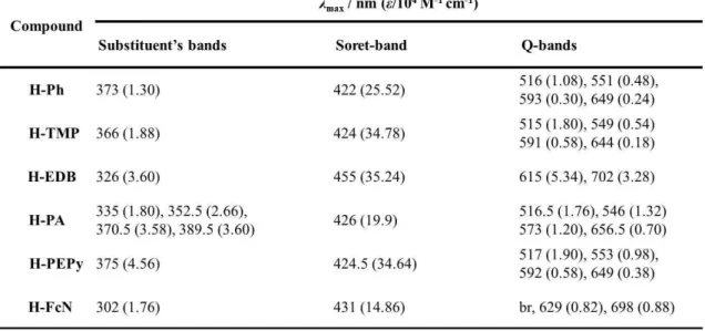
UV-vis absorption spectroscopy of the synthesized free-base porphyrins was conducted to investigate the effect of electron-donating and –withdrawing, π-conjugated and redox active substituents on the electronic states. UV-vis absorption spectra of the free-base porphyrins in 1,2-dichlorobenzene and the summary of absorption bands are shown in Figure 2 and Table 1, respectively. Note that the spectral data for 5,10,15,20- tetraphenylporphin (H-Ph) as a reference compound was also presented.
All free-base porphyrins present a strong absorption band at approximately 422- 455 nm and four weaker bands widely located at approximately 516-702 nm. These spectral features are caused by porphyrin macrocycle-based π-π* transitions described by Gouterman’s four orbital model.9 The former band in the shorter wavelength region is assigned to the S0→ S2 transition (Soret band), and the latter bands are attributed to the S0 → S1 transition (Q bands). In addition to these porphyrin-based absorption bands, bands attributed to the π-π* transition of the substituents at the meso-position are also observed in the UV region for all compounds. The Soret bands of H-TMP, H-FcN, H- PEPy and H-PA are slightly red shifted compared to that of H-Ph, indicating that the effect of the substituents on the electronic structure of the porphyrin moieties is relatively small. In contrast, the Soret band of H-EDB ( max = 455 nm) is largely shifted to the longer wavelength region compared to that of H-Ph ( max = 422 nm). Similarly, the Q- bands of H-EDB are largely red shifted compared to those of H-Ph, whereas the Q-bands of H-TMP, H-PEPy and H-PA are located almost similar position as those of H-Ph. These results indicate that electron-withdrawing nature of the dimesityldurylborane moieties largely affects the electronic structure of the porphyrin unit. In the case of H- FcN, broad Q bands at lower wavelength region compared to H-Ph was observed. This is because the smaller location barrier of ferrocenyl moieties compared to benzene rings.10
39
Figure 2. UV-vis absorption spectra of the free-base porphyrins in 1,2-dichlorobenzene (a) H-Ph, (b) H-TMP, (c) H-EDB, (d) H-PA, (e) H-PEPy and (f) H-FcN. (Insets) Enlarged UV-vis absorption spectra at Q-band regions.
40
Table 1. Summary of the absorption spectra for the free-base porphyrins in 1,2- dichlorobenzene.
41 Cyclic Voltammetry
Cyclic voltammograms of the free-base porphyrins are shown in Figure 3, and the redox potentials are summarized in Table 2. Electrochemical data of H-Ph as a reference compound was also presented. All measurements were performed in 0.1 M tetra-n-butylannmonium perchlorate (TBAP)/DMF solutions under an Ar atmosphere. As shown in Figure 3(a), H-Ph exhibits two reversible redox waves, which are assigned to the two-step one electron reduction of the porphyrin ring.11 Similar two reversible waves were observed for H-TMP and H-EDB. The half wave potentials (E1/2 / V vs. ferrocene/ferrocenium (Fc/Fc+)) of H-TMP (E1/2= −1.8β (first reduction) and −β.β5 V (second reduction)) are shifted to the negative potential compared to those of H-Ph (E1/2
= −1.54 (first reduction) and −1.λλ V (second reduction)), reflecting the electron-donating nature of 2,4,6-trimethoxyphenyl groups. In contrast, the half wave potentials of H-EDB, which possesses electron-withdrawing groups, are shifted to the positive potential region (E1/2 = −1.β6 (first reduction) and −1.77 V (second reduction)). These observation indicates that the introduction of the electron-donating and electron-withdrawing groups largely affects the LUMO and LUMO+1 level of the porphyrins. In the case of H-PA, three redox waves were observed at E1/2= −1.5γ, −1.λ4, and −β.4β V. The first two waves are attributed to the reduction process of the porphyrin ring and the potentials are similar to those of H-Ph. The third wave at −β.4β V is assignable to the reduction of the anthracenylphenyl groups.12 H-PEPy exhibits one reversible reduction wave at −1.43 V, which may be attributed to the reduction of the porphyrin ring. However, the second wave at −1.8 V became irreversible possibly due to the reduction of the substituents at the meso- positions.
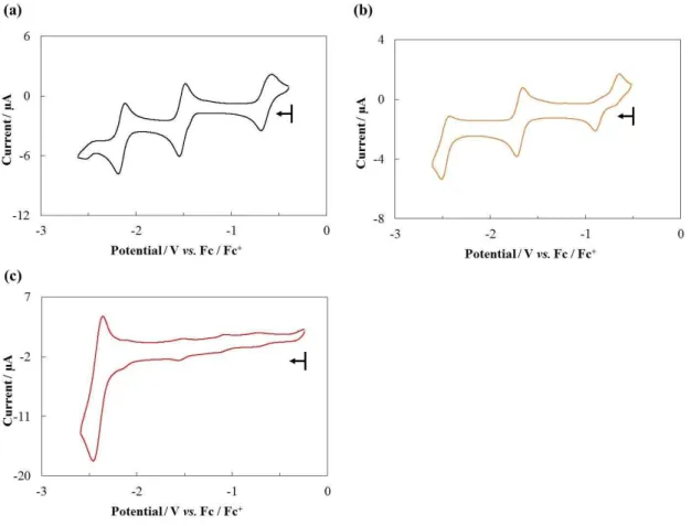
Cyclic voltammograms of the iron porphyrin complexes in 0.1 M TBAP/DMF solutions under Ar and the summary of the redox potentials are shown in Figure 4 and Table 3, respectively. Electrochemical data of 5,10,15,20-tetrakis(phenyl)porphyrinato iron(III) chloride (Fe-Ph) as a reference compound was also presented. Fe-Ph displayed three reversible redox waves at −0.6γ, −1.51 and −β.15 V, which are assigned to be Fe(III)/Fe(II), Fe(II)/Fe(I) and Fe(I)/Fe(0) redox couples.13 As shown in Figure 4b, Fe- TMP exhibited similar three reversible waves and the half-wave potentials are E1/2 =
−0.6γ, −1.51 and −β.15 V. All of the potentials were shifted to the negative potential
42
region compared to Fe-Ph, which was similar tendency as observed in the corresponding free-base porphyrin, H-TMP. In the cyclic voltammogram of Fe-PA, three redox waves attributed to the reduction of the porphyrin moiety at −0.74, −1.54 and −β.1γ V, and one additional wave attributed to the anthracenylphenyl groups was observed at −2.41 V. The redox potential of this forth wave was almost identical to that of the third wave observed in H-PA (−2.42 V).
The cyclic voltammogram of H-FcN, which has redox active substituents, in a 0.1 M TBAP/1,2-dichlorobenzene solution under Ar and the summary of the redox potentials are shown in Figure 5 and Table 4, respectively. Note that 1,2-dichlorobezene was used in this measurement because of the low solubility of the compound in DMF. H- FcN exhibited one quasi-reversible wave at −0.1λ V, which is assignable to the oxidation of the ferrocenyl groups. In the negative potential region, one reversible two-electron redox wave at −1.85 V and one reversible one-electron redox wave at −β.01 V were observed. The cyclic voltammogram of nitrobenzene exhibits reversible wave at −1.λ8 V (Figure 5c). Therefore, the wave at −1.85 V can be assigned to the reduction of the nitrophenyl moieties of H-FcN. The wave at −β.01 V is attributed to the reduction of the porphyrin ring. It should be noted that the second reduction of the porphyrin ring became unfavourable in H-FcN because of the two electron reduction at the nitrophenyl moieties.
43
Figure 3. Cyclic voltammograms of the free-base porphyrins ((a) H-Ph, (b) H-TMP, (c) H-EDB, (d) H-PA and (f) H-PEPy, 1.0 mM) in a 0.1 M TBAP/DMF solution under an Ar atmosphere (WE: GC; CE: Pt wire; RE: Ag+/Ag; scan rate: 20 mV s−1). Potential sweeps were started from the open circuit potential −0.6λ V (H-Ph), −0.5λ V (H-TMP),
−0.80 V (H-EDB), −0.41 V (H-PA) and −0.55 V (H-PEPy). Arrows in the voltammograms indicate the direction of potential sweep.
44
Table 2. Redox potentials of the prepared free-base porphyrins (E1/2 / V vs. Fc/Fc+) in DMF under an Ar atmosphere.
45
Figure 4. Cyclic voltammograms of the iron porphyrin complexes ((a) Fe-Ph, (b) Fe- TMP, and (c) Fe-PA, 1.0 mM) in a 0.1 M TBAP/DMF solution under an Ar atmosphere (WE: GC; CE: Pt wire; RE: Ag+/Ag; scan rate: 20 mV s−1). Potential sweeps were started from the open circuit potential −0.40 V (Fe-Ph), −0.5β V (Fe-TMP), and −0.β4 V (Fe- PA). Arrows in the voltammograms indicate the direction of potential sweep.
46
Table 3. Redox potentials of the prepared iron porphyrin complexes (E1/2 / V vs. Fc/Fc+) in DMF under an Ar atmosphere.
47
Figure 5. Cyclic voltammograms of the free-base porphyrins and nitrobenzene ((a) H- Ph, 1.0 mM (b) H-FcN 0.2mM, and (c) nitrobenzene, 0.2mM) in a 0.1 M TBAP/1,2- dichlorobenzene solution under an Ar atmosphere (WE: GC; CE: Pt wire; RE: Ag+/Ag; scan rate: 20 mV s−1). Potential sweeps were started from the open circuit potential −0.λγ V (H-Ph), −0.51 V (H-FcN), and −0.84 V (nitrobenzene). Arrows in the voltammograms indicate the direction of potential sweep.
48
Table 4. Redox potentials of the prepared free-base porphyrins and nitrobenzene (E1/2 / V vs. Fc/Fc+) in 1,2-dichlorobenzene under an Ar atmosphere.
49 Crystal Structure of H-PEPy
Single crystals of H-PEPy suitable for single crystal X-ray structural analysis were obtained by the diffusion of methanol into the dichloromethane solution of H-PEPy. An ORTEP drawing and packing structures of the obtained crystal are shown in Figure 6 and crystallographic data is summarized in Table 5. The compound crystallized in a monoclinic P21/a space group and one crystallographically independent H-PEPy molecule was observed in the structure. As shown in Figure 6, H-PEPy has one phenyl ring which has ethynylpyrenyl moiety and the remaining three phenyl rings have triflate groups. This observation is consistent with the result of 1H NMR spectroscopy (vide supra). The dihedral angle between the phenyl ring and the pyrenyl moiety was 53.7 deg. In the packing structure, CH-π interaction with the distance of 2.60 Å was formed between the phenyl ring and the pyrenyl moiety.
50
Figure 6. An ORTEP drawing and packing structures of H-PEPy. Thermal ellipsoids are shown at the 50% probability level. C = gray, N = pale blue, O= red, F = pale green, S = yellow and H = white.
51
Table 5. Summary of crystallographic data for H-PEPy Formula C65H33F9N4O9S3
Fw 1281.13
Color, habit purple, platelet
Crystal size, mm 0.503 × 0.493 × 0.028 Crystal system monoclinic
Space group P21/a
a (Å) 14.9896(3)
b (Å) 22.0654(5)
c (Å) 18.9156(5)
α (deg) 90
(deg) 104.2327(7)
(deg) 90
V (Å3) 6064.9(2)
Z 4
T (K) 123(2)
R1 0.0804
wR2 0.2625
GOF 1.078
52 Crystal Structure of H-FcN/TNCEL Co-crystal
Single crystals suitable for single crystal X-ray structure determination were obtained by the diffusion of hexane into the benzene solution of H-FcN containing organic acceptor, tetracyanoethylene (TCNE). The crystal structure of the obtained single crystal and the summary of crystallographic data are shown in Figure 7 and Table 6, respectively. One H-FcN and two 1,2,2-tricyanoethenolate (TCNEL) molecules are found as crystallographically asymmetric unit in this structure with triclinic P¯1 space group. It was previously reported that TCNE molecules can be converted to 1,2,2- tricyanoethenolate (TCNEL) via the reduction of TCNE and the subsequent reaction with dioxygen 14 or by the hydrolysis of TCNE 15 (Figure 8). As a result a co-crystal of H-FcN with TCNEL (H-FcN/TNCEL Co-crystal) is formed. In this structure, the main framework of porphyrin was distorted due to the change of their electronic state upon complexation with TCNEL. Judging from this result, we assumed that electron transfer mayoccur from porphyrin or ferrocenyl substituents to TCNEL because Webster and co- workers reported ferrocene is capable to form charge separated complex with TCNEL. π-Plane Cp ring of the ferrocenyl substituents in H-FcN are tilted about 30° against the porphyrin skeleton due to low energy barrier (< 10.4 kcal mol−1) for the rotation 10. In contrast, the dihedral angle between the π-Plane of 4-nitrophenyl group the porphyrin skeleton was approximately 50 deg, reflecting the bulkiness of the phenyl ring. For TCNEL, bond distances between the sp2 carbon atoms and the carbon atoms of CN groups are in the range of 1.42−1.52 Å, and the distances between the sp2 carbon atoms and oxygen atoms are 1.25 and 1.26 Å.
53
Figure 7. (a) Top and (b) side views of ORTEP drawings of H-FcN/TNCEL Co-crystal In the side view (b), hydrogen atoms are omitted for clarity.
54
Table 6. Summary of crystallographic data for H-FcN/TNCEL Co-crystal
Formula C62H36Fe2N12O6
Fw 1156.73
Color, habit navy blue, platelet
Crystal size, mm 0.265 × 0.261 × 0.034 Crystal system triclinic
Space group P-1
a (Å) 11.4777(3)
b (Å) 14.8574(4)
c (Å) 16.5932(5)
α (deg) 84.3794(8)
(deg) 86.1232(8)
(deg) 69.9196(7)
V (Å3) 2642.4(1)
Z 2
T (K) 123(2)
R1 0.0553
wR2 0.1568
GOF 1.054
55
Figure 8. Conversion of TCNE to TCNEL via (top) the reduction and (bottom) the hydrolysis.
56 IR spectrum of H-FcN/TNCEL Co-crystal
A fourier transform infrared (FT-IR) spectrum of H-FcN/TNCEL Co-crystal was measured to determine their chemical compositions. The IR spectra of H- FcN/TNCEL Co-crystal, H-FcN and TCNE are shown in Figure 9. The powder of H- FcN shows symmetrical and antisymmetric N-O stretching vibrations at 1341 and 1516 cm−1 which correspond to NO2 group. Similarly, we assign two peaks at 1343 and 1519 cm−1 in the spectrum of H-FcN/TNCEL Co-crystal to the symmetrical and antisymmetrical N-O stretching vibrations. In addition to these peaks, the small sharp peaks at 2217 and 2193 cm−1, which are attributed to the C-N stretching vibration which originates from TCNEL molecules and are comparable to the previously reported values.16 The C-N stretching vibration bands of TCNE were observed at higher wavenumber region (2264 and 2231 cm−1). The strength of the C-N bonds in TCNEL are weakened by the existence of its resonance structures (Figure 10).16
57
Figure 9. IR spectra of H-FcN (red line), TCNE (green line) and H-FcN/TNCEL Co- crystal (blue line).
58
Figure 10. Resonance structures of TCNEL.
59
Diffuse Reflectance Spectrum of H-FcN/TNCEL Co-crystal
UV-vis diffuse reflectance spectra of H-FcN and H-FcN/TNCEL Co-crystal in the solid state were shown in Figure 11. The spectrum of H-FcN exhibits several broad absorption bands from around 300 to 840 nm (Figure 11(a)). The spectral features may be caused by porphyrin macrocycle-based π-π* transitions. The measurement of H- FcN/TNCEL Co-crystal was performed in same condition as H-FcN, and a new broaden absorption band appeared at longer wavelength region (800 to 1500 nm) in addition to the porphyrin based absorption bands. This result clearly indicates the formation of charge transfer (CT) salt was formed in H-FcN/TNCEL Co-crystal. To investigate the origin of the CT absorption band, electronic transitions of the H-FcN and co-crystal of H-FcN/TNCEL Co-crystal were investigated by the time dependent density functional theory (TD-DFT) calculations using the Gaussian 09 17 programs with the B3LYP function18 and 6-31G (d) basis set 19. The calculated absorption spectra were drawn in Figure 11(b) and the frontier molecular orbitals of H-FcN/TNCEL Co-crystal are described in Figure 12. In the spectrum of H-FcN, the intense bands in the visible region are assigned to the π-π* transitions of the porphyrin macrocycle and the π-π* transitions of the substituents (Fc to C6H4NO2). For H-FcN/TNCEL Co-crystal, the absorption bands in the visible region are also corresponds to the π-π* transition between the occupied and unoccupied orbitals widely delocalized on the H-FcN molecule. Moreover, the broad absorption band from around 800 nm was obtained by calculation. Major contribution of the transition in longer wavelength was assigned to the transition from HOMO−β → LUMO (ƒ=0.101λ) at 1ββλ.7 nm, and mainly originate from charge transfer from ferrocenyl substituents to TNCEL and the porphyrin skeleton (Figure 12).
60
Figure 11. (a) Diffuse reflectance spectra of H-FcN (red line) and H-FcN/TNCEL Co- crystal (blue line) (b) Simulated absorption spectra of H-FcN (red line) and H- FcN/TNCEL Co-crystal (blue line).
61
Figure 12. Frontier molecular orbitals of H-FcN/TNCEL Co-crystal on the basis of single point DFT calculations.
62
Conclusion
This chapter described the syntheses of various kinds of porphyrins and metalloporphyrins bearing electron-donating and withdrawing, π-conjugated and redox active substituents at the meso positions. The synthetic route to obtain each porphyrin derivatives were successfully optimized by considering the nature of each substituent and five kinds of free-base porphyrins (H-TMP, H-EDB, H-PA, H-PEPy and H-FcN) and three kinds of iron porphyrin complexes (Fe-TMP, Fe-PA and Fe-PEPy) were obtained. Moreover, UV-vis absorption spectroscopy and electrochemical studies of the obtained compounds were performed. The results of these measurements were compared with the reference compounds, H-Ph and Fe-Ph, and the effect of the substituents on the electronic structures of the molecules was discussed. I also examined the crystallization of the porphyrin bearing redox active ferrocenyl moieties, Fc-N. The crystals of Fc-N were obtained as by the recrystallization in the presence of organic acceptor molecules, TCNE. Single crystal X-ray structural analysis revealed that TCNE is reduced to TCNEL and the co-crystal of Fc-N and TCNEL (Fc-N/TCNEL Co-crystal) is formed. The electronic structure of Fc-N/TCNEL Co-crystal was investigated using IR spectroscopy, diffuse reflectance UV-vis spectroscopy, TD-DFT calculations, and the charge transfer interaction between Fc-N and TCNEL was indicated.
63
Experimental
Materials and Methods
Pyrrole was purchased from Sigma-Aldrich Co., LLC. 9-bromoanthracene, 4- bromobenzaldehyde, n-butyllithium (nBuLi), 1,2-dichlorobenzene, dimethylsulfoxide (DMSO), ethyl acetate, diethylamine, trimethylamine, ferrocene (Fc), ferrocenecarbaldehyde, 4-formylphenylboronic acid, iodine, iron(II) chloride tetrahydrate, 1-pyrenecarbaldehyde, trifluoroacetic acid (TFA), bis(triphenylphosphine)palladium(II) dichloride, potassium hydroxide, and tripotassium phosphate were purchased from Wako Pure Chemical Industries, Ltd. Chloroform, hexane (Hex), N,N-dimethylformamide (DMF) and pyridine were purchased from Kanto Chemical Co., Inc. Tetrabutylammonium fluoride (TBAF) (ca. 1 mol/L in tetrahydrofuran), tetra(n-butyl)ammonium perchlorate (TBAP), bromine, 1-bromopyrene, N-bromosuccinimide, 2,3-dichloro-5,6-dicyano-1,4-benzoquinone, trifluoromethanesulfonic anhydride, formaldehyde solution (37%), 4- hydroxymezaldehyde, dimesitylfluoroborane, trimethylsilylacetylene, 2,4,6- trimethoxybenzaldehyde, 4-nitrobenzaldehyde and 4-phenylbenzaldehyde were purchased from Tokyo Chemical Industry Co., Ltd. Copper iodide was purchased from Nacalai tesque Co., Ltd. CDCl3 was obtained from Cambridge Isotopes, Inc. Diethylamine and trimethylamine were used after distillation. Another reagents were used without further purification. TBAP was recrystallized from absolute ethanol and dried in vacuo. Dichloromethane (DCM) and tetrahydrofuran (THF) were degassed and purified under an N2 atmosphere using a GlassContour solvent system (Nikko Hansen Co., Ltd.).
1H NMR spectra were recorded on a JEOL 400 MHz instrument. All 1H NMR spectra were referenced against residual proton signals. Elemental analyses were measured on a MICRO CORDER JM10. Electrochemical experiments were performed under argon and CO2 atmospheres using a BAS ALS Model 650DKMP electrochemical analyzer. Cyclic voltammograms were recorded in 1,2-dichlorobenzene ([complex] = 1.0 mM; 0.1 M TBAP) using a glassy carbon disk, a platinum wire and an Ag+/Ag electrode (Ag/0.01 M AgNO3) that were used as the working, auxiliary, and reference electrodes, respectively. The redox potentials of the samples were calibrated against the redox signal for the ferrocene/ferrocenium (Fc/Fc+) couple. UV-vis absorption measurements were
64
performed on a Shimadzu UV-1800 spectrometer at room temperature.
65 Syntheses
Synthesis of 5-(2,4,6-trimethoxyphenyl) dipyrromethane: To a mixture of 2,4,6- trimethoxybenzaldehyde (3.0 g, 15 mmol) and pyrrole (27 mL, 0.38 mol) was added TFA (0.12 mL, 1.5 mmol) at rt. The mixture was stirred for 10 min at rt, and the reaction was quenched by 1M NaOH aq. The resulting mixture was extracted with ethyl acetate. The extract was dried over anhydrous Na2SO4, and concentrated under reduced pressure. The resulting mixture was purified by column chromatography (DCM:ethyl acetate:Hex = 7:3:1) to afford a desired product (1.0 g, yield 22%). 1H NMR (400 MHz, CDCl3) δ 8.46 (s, 2H), 6.61 (dd, J = 4.3, 2.7 Hz, 2H), 6.17 (s, 2H), 6.07 (q, J = 2.8 Hz, 2H), 6.04 (s, 1H), 5.88 (q, J = 0.8 Hz, 2H), 3.79 (s, 3H), 3.71 (s, 6H) ppm.
Synthesis of 5,10,15,20-tetrakis(2,4,6-trimethoxyphenyl)porphyrin (H-TMP): To a solution of 2,4,6-trimethoxybenzaldehyde (0.40 g, 2.0 mmol) and 5-(2,4,6- trimethoxyphenyl) dipyrromethane (0.62 g, 2.0 mmol) in dry DCM (200 mL) was added TFA (77 L, 1.0 mmol) at rt. The mixture was stirred for λ0 min at rt and then chloranil (0.49 g, 2.0 mmol) was added. After 90 min, the reaction mixture was passed through alumina short column to quench the reaction. The resulting mixture was purified by column chromatography (chloroform) to afford a purple solution. The desired product was recrystallized from chloroform and Hex, and washed by Hex to give a purple solid (0.37 g, yield 38%). 1H NMR (400 MHz, CDCl3) δ 8.68 (s, 8H), 6.53 (s, 8H), 4.06 (s, 1βH), γ.47 (s, β4H), −β.56 (s, βH) ppm.
Synthesis of 5,10,15,20-tetrakis(2,4,6-trimethoxyphenyl)porphyrinato iron(III) chloride (Fe-TMP): To a solution of H-TMP (0.10 g, 0.10 mmol) in DMSO (26 mL), a DMSO 15 mL) solution of FeCl2·4H2O (0.12 g, 0.62 mmol) was added dropwise at room temperature. The mixture was refluxed for 1 h and then cooled to room temperature. After evaporating half volume of the solvent, 6 M HCl was added into the resulting mixture and the solution was filtrated. The desired product was washed by 3 M HCl and then, extraction by DCM was performed. The extract was dried over anhydrous Na2SO4, and concentrated under reduced pressure. (80 mg, yield 73%). Anal. Calcd for C56H52ClFeN4
O12⸱2H2O: C, 61.13; H, 5.13; N, 5.09. Found: C, 61.11; H, 4.85; N, 5.04%.