Diagnosis in Designs with Block Compactors
Thomas Clouqueur1, Kamran Zarrineh2, Kewal K. Saluja3, Hideo Fujiwara1
1Graduate School of Information Science, Nara Institute of Science and Technology, Japan.
2AMD Corporation, USA.
3University of Wisconsin-Madison, USA.
Abstract
While drastically reducing the test volume and the test application time, test response compactors lose the lo- cation of errors in the scan chains, which is necessary for diagnosis. This paper proposes a method to re- trieve that information from the signatures produced by block compactors. The error diagnosis efficiently searches for the errors by making some assumptions about the shape of error vectors and learning from pre- vious results. Experiments show that over 95% diag- nostic coverage can be reached in practice.
1 Introduction
Increase of logic density results in a growing amount of data required to test the chips with scan design. Such data is stored on testers and transfered between the tester and the chip through test channels with lim- ited bandwidth. Thus, large test volume may ex- ceed the memory available on the tester and it impacts test application time dramatically. To overcome these problems, the test volume can be reduced by com- pressing the stimuli and compacting the test response. Reduction of two orders of magnitude are achieved at the input side, in particular by exploiting the low fill rate of test cubes. At the output side, space com- pactors can funnel wide response vectors into a single output and time compactors can compile the response sequence into a signature of a few bits. Such com- paction can be done without impacting the fault cov- erage, although such performance may require to de- rive a special test set or add extra inputs to modify the output data prior to compaction. However, the com- paction severely impacts the diagnostic capability be- cause many erroneous patterns produce the same sig- nature at the compacted outputs.
Diagnostic can be performed using time and space
information about the erroneous test response. Time information, given by the set of failing test patterns, can be used for fault model dependent diagnostic. Space information, given by the set of scan cells where errors occurred, can be used for diagnostic based on cone of logic methods. Both types of information can be used concurrently to achieve higher diagnostic res- olution, but it requires obtaining the exact position of the errors in the test response. In the presence of a compactor, the space and time information are not di- rectly available. Indeed, compactors transform blocks of output bits that can span in the space dimension, time dimension or both. Therefore, an error observed at the compacted outputs can be produced by an er- ror or errors occurring at several locations and several clock cycles.
Fault diagnosis algorithms can be performed di- rectly from the compacted test response by consider- ing the compactor as part of the circuit [5]. How- ever, fault diagnosis usually requires to know which scan cells captured errors and at what time during test. The problem considered in this paper, namely error diagnosis, is to derive the location of errors in space and time within the test response for designs with compactors. Such error diagnosis enables using tra- ditional fault diagnosis from the error response in the scan cells. Moreover, the performance of error diag- nosis for a compactor indicates the quality of the com- pactor even when fault diagnosis is to be performed on a lumped design.
In this paper, we first present an overview of the schemes previously proposed for diagnostic in the presence of compactors. Then, in Section 3, we de- scribe the architecture of space compaction used. In Section 4, we present the algorithm used for error di- agnosis, which is then evaluated in Section 5. The pa- per concludes with Section 6.
11th IEEE European Test Symposium, pp. 199-204, May 2006.
2 Previous work
We first describe the works related to diagnostic with time compactors. Compactors used during pass/fail test mode usually have some but limited diagnostic ca- pabilities. For time compaction with a linear feedback shift register (LFSR) of size n, it was shown that a single error can be localized in a stream of m bits if m < 2n [12]. However, the occurrence of more er- rors in the response stream results in diagnostic alias- ing. Such aliasing can be avoided by reapplying the test and directly observing the identified error loca- tion. If the error is not observed, the signature can be analyzed again with different assumptions on the error pattern [4]. The size of the LFSR can also be chosen to obtain a desired diagnostic resolution for a given size of circuit, although high resolution usually requires impractical size of LFSR [15]. Furthermore, the diagnostic aliasing probability can be reduced by using signature analysis registers that work with non- primitive polynomials [20].
Many techniques have been developed to modify the compaction scheme during diagnostic to allow lo- calization of errors in time and space dimensions. The techniques have the common property to decrease the compaction ratio compared to the pass/fail mode, ei- ther by increasing the size of the data observed or by applying the test sequence multiple times. One of the approaches used in time compaction schemes is to check the signature multiple times during test applica- tion, thus splitting the test sequence into windows [18]. Windows resulting in fault free signatures consist of non erroneous response while other windows can be applied again with full response observation to iden- tify the errors. The efficiency of the scheme can be improved by using windows of varying length [6]. An- other approach is to compact only part of the scan cells at a time and apply the test multiple times with differ- ent cell partitions until all the erroneous scan cells are identified [1, 2, 3, 10, 11, 16]. Such scheme can only gather space information for diagnostic and requires special control to select the scan cells observed at a given test instance. Yet another approach is to compute multiple signatures by applying the test sequence mul- tiple times with different feedback polynomials in the LFSR [23]. Beside increasing substantially the test ap- plication time, such a scheme requires solving a large set of complex equations to identify the errors in the input sequence. Finally, a general approach is to sup- press time compaction during the diagnostic phase, for example by removing the feedback line on LFSR and observing the full quotient [22].
Approaches that tradeoff hardware overhead for re- duced test application time have also been proposed. Some methods use cycling registers beside the signa- ture analyzer to improve the diagnostic [9, 19]. Other schemes use very long signatures or multiple signature analyzers, requiring again to solve a large set of com- plex equations in order to identify the errors within the input sequence.
In the case of space compaction, the most common approach is to bypass the compactor during diagnostic and observe only a limited number of scan chains for a given test instance [22]. However, some error patterns can also be identified from the compacted response. For a compactor implementing the check matrix of an error correcting code of distance d, t errors in the presence of x unknown values can be identified within the compactor input vector if 2t + x < d [14, 17]. During diagnosis, the compaction ratio can be reduced while increasing the error correction capability of the compactor [7]. Errors can also be identified without decreasing the compaction ratio by using advanced search algorithms that do not guarantee strong diag- nosis capability but may work well in practice. Con- volutional compactors were shown to correctly diag- nose over 90% of the error patterns produced by indus- trial circuits while keeping the compaction ratio over 100 [13]. In this paper, we propose an error diagnosis algorithm for block compactors [21, 8] to be used at full compaction ratio.
3 Block compactor architecture
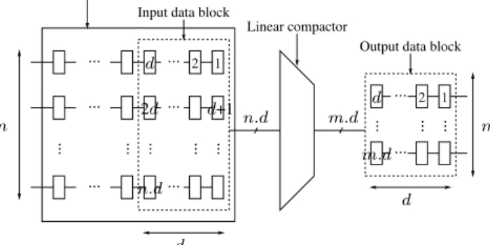
The general architecture of the circuit under test (CUT) and the compactor is presented in Figure 1. The circuit has n scan chains that are funneled into m compacted outputs to be observed by a tester. The linear transformation considers blocks of depth d and size n.d, and outputs blocks of depth d and size m.d so that one output block can be scanned out as the next input block is shifted out in the scan chains.
The linear compactor multiplies the input block by a check matrix H of size n.d × m.d so that the output block is a linear combination of the n.d rows of H. Any check matrix H can be used by routing the scan cells in the last d stages of the scan chains to the linear compactor. However, to avoid such intrusive design, we assume that only the last stage of the scan chain is connected to the linear compactor as shown in Fig- ure 2. With such design, the H matrix has a special form since the row associated with two scan cells be- longing to the same scan chain are shifted versions of
... ...
...
... ...
...
... ...
...
...
...
...
...
... ... ...
CUT with scan chains
Linear compactor
Output data block Input data block
2 1
1 2d 2
d
d
m
n n.d
d
n.d
d
m.d
d+1 m.d
Figure 1: Test architecture.
each other. For the compactor of Figure 2, two scan chains are compacted into one output by using a depth of five. The rows associated to the cells in the input block are:
cell row
5 01011
4 10101
3 11010
2 01101
1 10110
10 11100
9 01110
8 00111
7 10011
6 11001
Note that non intrusive designs require extra memory elements but less XOR gates than intrusive designs. Also, in order to continuously shift out the scan chains, a shadow register is used to store the compacted re- sponse computed every d cycles. The values contained in the compaction register can be either reset every d cycles or the expected compacted response can be sal- vaged after errors occur [18].
Chain 1 Chain 2
Output Shadow
register Compaction
register
Figure 2: Linear compactor.
For the compactors used in this paper, the XOR tree is chosen so that the H matrix has non-zero rows that are all different and with identical weight of three.
Thus, H is a check matrix of an error correcting code of distance at least four and one error is guaranteed to be correctly identified within each input block [14]. Such single error diagnosis can be performed using a dictionary mapping the error pattern produced by sin- gle errors to the error position in the input block. Nev- ertheless, error patterns produced by faults may con- tain more than one error per block in general. There- fore, advanced search algorithms are needed to iden- tify error patterns of varying multiplicity.
4 Diagnosis algorithm
The diagnosis procedure is based on a search function that considers an erroneous output block called signa- tureand returns an erroneous input block that produces the given signature. Such input block is not unique in general and therefore the method is prone to alias- ing. The basic search function consists of a depth first search algorithm in which error location candidates are chosen recursively. After selecting a candidate, the signature is updated to account for the contribution of the newly selected candidate. The search goes on selecting new candidates until the selected candidates produce the given signature or until a stopping crite- ria is reached, in which case the search backtracks. Several heuristics are used to guide the basic search towards the correct solution while limiting the search space.
Guiding the search
A dictionary is used to efficiently select candidates at each node of the search tree. We observed that errors often happen in burst within the scan chains. There- fore, the dictionary is built for burst of one, two... up to b errors in the input block. Note that the size of such dictionary is b.n.d and b = 4 was usually found sufficient so that the dictionaries remain small. Each entry in the dictionary consists of a list of one up to b successive errors and the corresponding signature. At each step of the search, every entry in the dictionary is given a score that indicates if the corresponding errors are good candidates. The score is a function of three factors: the correlation between the current signature searched for and the signature of the candidate, the correlation between the candidate and the previously selected candidates in the current search, and the cor- relation between the candidates and the error patterns returned in previous searches.
Clearly, the likeness of the signature corresponding to some candidates with the current signature searched for should guide the search algorithm. To account for
such correlation, the score is a function of the ham- ming distance between the two signatures. Further- more, errors tend to be located in close proximity of each others, when not in burst. To give priority to these clustered errors, the score is a function of the average minimum distance between the candidates and the al- ready selected candidates. Finally, we guide the search by learning from previous diagnosis results. Our ba- sic search algorithm is embedded in a diagnosis proce- dure that analyzes all the error signatures produced by a faulty device. The error signatures are collected in- dependently one of the others to simplify the diagnosis albeit at the cost of extra test application time since the last input block of each test response is only partially used. Some vectors produce identical signatures (usu- ally corresponding to identical error responses) and we collect the different error signatures along with their frequency of occurrence. Assume that p different sig- natures are collected. They consist of several output blocks that are analyzed separately. Some signatures are easier to diagnose than others because they are produced by less errors. The number of errors in the signature indicates the number of errors in the input block as long as errors do not cancel out during com- paction. Nevertheless, such error cancellation is fre- quent and we rely on another measure to judge the easiness of diagnosing a signature. We observe that er- ror signature happening frequently during test are usu- ally produced by few errors. Therefore, the diagno- sis procedure considers first the error signatures hap- pening more frequently. To break ties, the signatures with less errors are considered first. Starting diagnosis with easy signatures, we expect the first signatures to be correctly diagnosed and we use the first diagnosis results to guide the subsequent searches. Indeed, we observe that errors tend to occur in the same vicinity for different test patterns. To account for that corre- lation, we record a few locations returned by the first diagnosis procedures. The score given to the candi- dates is a function of the average minimum distance between the candidates and these first returned candi- dates.
The guided diagnosis algorithm is presented in Fig- ure 3 where D is the size of the dictionary. The func- tion select in the search algorithm consists in check- ing that the candidates corresponding to entry i of the dictionary are not already selected, in which case the function return false. The function also updates the list of candidates selected and the signature.
Limiting the search space
Searching the full space of solution would require impractical time. Therefore, some stopping crite-
search(){
if(signature==0) return true; done=false;
compute score(dictionary,selected,history); order dictionary(score);
i=0;
while((not done) and (i<D)){ if(select(dictionary(i))){
done=search();
if(not done) unselect(dictionary(i)); }
i++; }
return done; }
diagnose(){
collect error signatures; for(i=0;i<nb blocks;i++){
clear history;
order signature block[i](frequency); for(j=0;j< p;j++){
signature=signature block[i][j]; search();
update history(errors found); }
} }
Figure 3: Guided diagnosis algorithm.
ria are used to prune the search tree. First, we set a maximum number of errors to be selected, M AX SELECT ED, so that function select returns falsewhen the size of the set of selected errors exceeds M AX SELECT ED. We also limit the number of candidates considered at each step by replacing the check “i < D” by “(nb selected.a+ b)i < D”, where nb selectedis the number of errors currently selected. The parameter b specifies what fraction of the dictio- nary is to be searched at the first node. The parameter a allows to further restrict the search as candidates get selected.
5 Experimental results
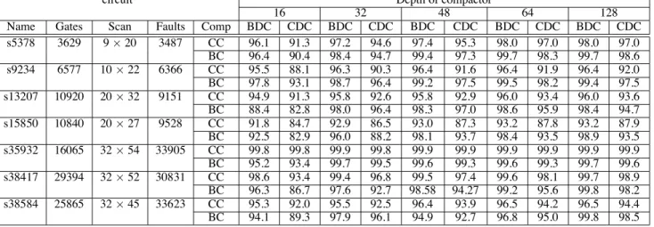
We evaluated our diagnosis algorithm for the erro- neous test response produced by stuck at faults in IS- CAS’89 benchmark circuits with full scan. The diag- nosis performance is measured by the basic diagnostic
circuit Depth of compactor
16 32 48 64 128
Name Gates Scan Faults Comp BDC CDC BDC CDC BDC CDC BDC CDC BDC CDC
s5378 3629 9 × 20 3487 CC 96.1 91.3 97.2 94.6 97.4 95.3 98.0 97.0 98.0 97.0 BC 96.4 90.4 98.4 94.7 99.4 97.3 99.7 98.3 99.7 98.6 s9234 6577 10 × 22 6366 CC 95.5 88.1 96.3 90.3 96.4 91.6 96.4 91.9 96.4 92.0 BC 97.8 93.1 98.7 96.4 99.2 97.5 99.5 98.2 99.4 97.5 s13207 10920 20 × 32 9151 CC 94.9 91.3 95.8 92.6 95.8 92.9 96.0 93.4 96.0 93.6 BC 88.4 82.8 98.0 96.4 98.3 97.0 98.6 95.9 98.4 94.7 s15850 10840 20 × 27 9528 CC 91.8 84.7 92.9 86.5 93.0 87.3 93.2 87.8 93.2 87.9 BC 92.5 82.9 96.0 88.2 98.1 93.7 98.4 93.5 98.9 93.5 s35932 16065 32 × 54 33905 CC 99.8 99.8 99.9 99.8 99.9 99.9 99.9 99.9 99.9 99.9 BC 95.2 93.4 99.7 99.5 99.6 99.3 99.6 99.3 99.7 99.6 s38417 29394 32 × 52 30831 CC 98.6 93.4 99.4 96.8 99.5 97.4 99.6 98.1 99.7 98.9 BC 96.3 86.7 97.6 92.7 98.58 94.27 99.2 95.6 99.8 98.2 s38584 25865 32 × 45 33623 CC 95.3 92.0 95.5 92.5 96.4 93.9 96.5 94.2 96.5 94.4 BC 94.1 89.3 97.9 96.1 94.9 92.7 96.8 95.0 99.8 98.5
Table 1: Diagnostic coverage for ISCAS’89 circuits
coverage (BDC) and compound diagnostic coverage (CDC) defined in [13]. For a given fault, we mea- sure the number of erroneous response patterns that are correctly diagnosed, i.e. for which the set of er- rors selected by the diagnosis algorithm is exactly the set of errors in the response. If at least one pattern is correctly diagnosed, BDC considers that the fault is correctly diagnosed, while CDC records the ratio of correctly diagnosed patterns. BDC and CDC are then averaged over all the faults.
The results for block compactor (BC) diagnosis are presented in Table 1 along with the results the convo- lutional compactor (CC) presented in [13]. For each benchmark circuit, the BDC and CDC are measured for a depth of compactor varying from 16 up to 128 while the number of outputs remains one.
The experimental results can be directly compared with those derived for diagnosis with convolutional compactor since the same benchmark circuits with same scan configuration and the same coverage met- rics were used. Nevertheless, the experiments most likely differ in the scan orders and the test sets used. In general, error diagnosis is more successful when only a few errors produce the signature. Block compactors divide the errors among the blocks while convolutional compactors analyzes a flow of responses without divi- sions. Such difference may give advantage to block compactors but the performances also rely on the dif- ferent heuristics proposed for convolutional and block compactors.
First, the results show that the diagnostic perfor- mance usually improves as the depth of the compactor increases. Indeed, the size of the signature space grows exponentially with the depth, thus the probability that different error patterns produce the same signature de-
creases as the depth increases. For depth of 16, the performance is relatively poor because aliasing is very frequent. Note also that the performance sometimes decreases when the depth increases, for example for circuit s38584 when the depth increases from 32 to 48. Since the scan depth is 45, two blocks are neces- sary to compact the response for depth 32 while only one block is used for depth 48. Dividing the errors be- tween two blocks gives better performance despite the lower resolution of signatures of size 32. Secondly, the performance appears to be circuit specific but some- what independent of the circuit size. Note that the cir- cuits use different compaction ratios ranging from 9 up to 32. In General, the diagnostic coverage decreases as the compaction ratio increases but we obtain better results for some circuits with high compaction ratio compared to other circuits with low compaction ratio. Comparing our results with the performance of di- agnostic with convolutional compactor, we observe that our approach is superior in a majority of cases. Nevertheless, we are usually outperformed for depth of 16 and for circuits s35932 and s38417. Some of the heuristics used by the diagnosis algorithm developed for convolutional compactor may be specially effec- tive in those cases. In particular, we have not consid- ered limiting the search to errors within a subset of the scan chains. Furthermore, convolutional compactors outperform block compactors in some cases where the compactor depth is just above the scan depth, e.g. for circuit s38584 with depth of d=48. In such cases, block compactors collect one signature of size d for each test response while convolutional compactors collect a signature of size d+ scan depth, which is nearly twice as long. For the diagnostic approaches considered, convolutional compactors always collect
more information to perform diagnosis which impact test application time and makes the performance com- parison more or less biased in favor of convolutional compactor. Overall, our results show that block com- pactors can achieve high performance at small depth, i.e. small hardware cost, by dividing errors among blocks. Moreover, the search algorithm using dictio- naries appears to be very effective.
6 Conclusion
This paper proposed an approach to localize errors in the test response using the signatures produced by block compactors. We use a design of block com- pactors that is non intrusive, has low hardware and can funnel any number of scan chains into a single output. The error diagnostic relies on some heuristics inspired from the expected characteristics of the error response. The algorithm is based on a depth first search that is guided by a dictionary, the history of diagnostic out- puts and the proximity of errors.
The experimental results show the effectiveness of the diagnostic approach proposed with diagnostic cov- erage usually exceeding 95%. Our approach was shown to be superior to the diagnostic with convolu- tional compactor for most cases, although the compar- ison was biased in favor of convolutional compactors. Nevertheless, some of the heuristics proposed in [13] may improve our performance and need to be consid- ered. Other future work includes error diagnosis in presence of X values in the response.
Acknowledgments
This work was supported in part by 21st Century COE Program and in part by Japan Society for the Promotion of Science (JSPS) under Grants-in-Aid for Scientifi c Research B(2)(No. 15300018) and the grant of JSPS Research Fel- lowship (No. L04509).
References
[1] I. Bayraktaroglu and A. Orailoglu, “Deterministic partitioning techniques for fault diagnosis in scan- based bist,” in Proc. ITC, pp. 273–282, 2000.
[2] I. Bayraktaroglu and A. Orailoglu, “Improved fault diagnosis in scan-based bist via superposition,” in Proc. DAC, pp. 55–58, 2000.
[3] I. Bayraktaroglu and A. Orailoglu, “Diagnosis for scan-based bist: Reaching deep into the signatures,” in Proc. DATE, pp. 102–109, 2001.
[4] J. Chan and B. Womack, “A study of faulty signa- ture for diagnostics,” in Proc. ISCAS, pp. 2701–2704, 1990.
[5] W.-T. Cheng, K.-H. Tsai, Y. Huang, N. Tamarapalli, and J. Rajski, “Compactor independent direct diagno- sis,” in Proc. ATS, pp. 204 – 209, 2004.
[6] T. Clouqueur, O. Ercevik, K. Saluja, and H. Taka- hashi, “Effi cient signature-based fault diagnosis us- ing variable size windows,”in Proc. VLSI Design, pp. 391–396, 2001.
[7] T. Clouqueur, K. K. Saluja, and H. Fujiwara, “A class of linear space compactors for enhanced diagnostic,” in Proc. ATS, 2005.
[8] T. Clouqueur, K. K. Saluja, and H. Fujiwara, “Design and analysis of multiple weight linear compactors of responses containing unknown values,” in Proc. ITC, 2005.
[9] J. Ghosh-Dastidar, D. Das, and N. Touba, “Fault di- agnosis in scan-based bist using both time and space information,” in Proc. ITC, pp. 95–102, 1999. [10] J. Ghosh-Dastidar and N. Touba, “A rapid and sclable
diagnosis scheme for bist environments with a large number of scan chains,” in Proc. VTS, pp. 79–85, 2000.
[11] C. Liu and K. Chakrabarty, “A partition-based ap- proach for identifying failing scan cells in scan-bist with applications to system-on-chip fault diagnosis,” in Proc. DATE, pp. 230–235, 2003.
[12] W. McAnney and J. Savir, “There is information in faulty signatures,” in Proc. ITC, pp. 630–636, 1987. [13] G. Mrugalski, A. Pogiel, J. Rajski, J. Tyszer, and
C. Wang, “Fault diagnosis in designs with convolu- tional compactors,”in Proc. ITC, pp. 498 – 507, 2004. [14] J. H. Patel, S. S. Lumetta, and S. M. Reddy, “Applica- tion of saluja-karpovsky compactors to test responses with many unknowns,” in Proc. VTS, pp. 107–112, 2003.
[15] J. Rajski and J. Tyszer, “On the diagnostic proper- ties of linear feedback shift register,” IEEE Trans. on CAD, vol. 10, pp. 1316–1322, oct 1991.
[16] J. Rajski and J. Tyszer, “Diagnosis of scan cells in bist environment,”IEEE Trans. on Computers, vol. 48, pp. 724–731, jul 1999.
[17] K. K. Saluja and M. Karpovsky, “Testing computer hardware through data compression in space and time,” in Proc. ITC, pp. 83–88, 1983.
[18] J. Savir, “Salvaging test windows in bist diagnostics,” in Proc. VTS, pp. 416–425, 1997.
[19] J. Savir and W. McAnney, “Identifi cation of failing tests with cycling registers,” in Proc. ITC, pp. 322– 328, 1988.
[20] C. Stroud and T. Damarla, “Improving the effi ciency of error identifi cation via signature analysis,” in Proc. VTS, pp. 244–249, 1995.
[21] C. Wang, S. M. Reddy, I. Pomeranz, J. Rajski, and J. Tyszer, “On compacting test response data contain- ing unknown values,” in Proc. ICCAD, pp. 855–862, 2003.
[22] P. Wohl, J. Waicukauski, S. Patel, and G. Maston, “Ef- fective diagnostics through interval unloads in a bist environment,” in Proc. DAC, pp. 249–254, 2002. [23] Y. Wu and M. Adham, “Scan-based bist fault diagno-
sis,” IEEE Trans. on CAD, vol. 18, pp. 203–211, feb 1999.