Functional Unit and Register Binding Methods
for Hierarchical Testability
Jun NISHIMAKI
†, Toshinori HOSOKAWA
‡and Hideo FUJIWARA
†††Graduate School of Industrial Technology, Nihon University, 1-2-1 Izumicho, Narashino, Chiba 275-8575, Japan
‡College of Industrial Technology, Nihon University, 1-2-1 Izumicho, Narashino, Chiba 275-8575, Japan
††Faculty of Informatics, Osaka Gakuin University, 2-36-1 Kishibe-Minami, Suita, Osaka 564-8511, Japan
E-mail: †[email protected], ‡[email protected], ††[email protected]
AbstractAlthough several test generation algorithms have been proposed for sequential circuits, high fault coverage is difficult to achieve in a reasonable amount of time. Hierarchical test generation methods using functional-register transfer level circuits have been proposed as efficient test generation methods for sequential circuits. Hierarchical test generation methods generate test sequences using functional-register transfer level circuits before binding in behavioral synthesis. Therefore, fault coverage for test sequences generated by hierarchical test generation depends on the binding results. This paper proposes a binding method for hierarchical testability that uses the results of hierarchical test generation to achieve high fault coverage. Experimental results reveal the effectiveness of the proposed method.
Keywords: hierarchical test generation, test environment, behavioral synthesis, binding, functional-register transfer level
I. INTRODUCTION
Recent advances in semiconductor technologies have resulted in exponential increases in VLSI circuit density and complexity, which has in turn increased the test generation time. Efficient test generation algorithms for combinational circuits have been proposed [1-5]. These algorithms can achieve high fault coverage even for large circuits. Several test generation algorithms for sequential circuits have been also proposed. However, compared to that for combinational circuits, the search space of test generation for sequential circuits is enormous, and so it is very hard to achieve high fault efficiency in a reasonable amount of
time.
On the other hand, increases in VLSI circuit density and complexity result in a decrease in design productivity. As a result, VLSI design at the register-transfer level (RTL) is becoming difficult. In order to resolve this problem, behavioral synthesis [6] has been proposed in order to improve design productivity.
In general, behavioral synthesis consists of two steps, namely, scheduling and binding [6]. In the scheduling step, the operation execution time is determined for each operation in the behavioral description. In the binding step, functional units and registers are assigned to each operation and each variable in the behavioral description, respectively. Circuits synthesized after scheduling are referred to as functional RTL circuits, and circuits synthesized after scheduling and binding are referred to as structural RTL circuits.
Hierarchical test generation methods using functional RTL circuits have been proposed as efficient test generation methods for sequential circuits [7-9]. These hierarchical test generation methods generate test sequences using functional RTL circuits before binding in behavioral synthesis. Therefore, the number of testable functional units and the number of detectable faults for generated test sequences depends on the binding results. In order to achieve high fault coverage in hierarchical testing, it is important to test as many functional units as possible using the generated test sequences. As such, binding methods for hierarchical testability to increase the number of testable functional units have been proposed [10, 11].
These methods [10, 11] perform functional unit binding using hierarchical test generation results and synthesize
14th IEEE Workshop on RTL and High Level Testing (WRTLT'13), November 2013.
structural RTL circuits such that several synthesized functional units become testable. However, depending on the hierarchical test generation results, some synthesized functional units become untestable. In [11], the authors did not consider testing these untestable functional units. Hence, if several untestable functional units are synthesized, achieving high fault coverage is not guaranteed. In [10], if some synthesized functional units are untestable, test multiplexers are inserted into the RTL data path in order to make these units testable. However, insertion of test multiplexer increases the area overhead and degrades the data path performance.
In [10] and [11], testability is considered only for functional unit binding, and not for register binding. It is expected that higher fault coverage can be achieved by considering testability not only in functional unit binding but also in register binding.
This paper proposes a functional unit and register binding method for hierarchical testability that uses the hierarchical test generation results to achieve high fault coverage in hierarchical testing. The remainder of this paper is organized as follows. Section II describes the hierarchical test generation method using functional RTL circuits. A binding method for hierarchical testability is proposed in Section III. Section IV presents the experimental results. Finally, Section V concludes the paper and discusses areas for future research.
II. HIERARCHICAL TEST GENERATION This section describes a hierarchical test generation method using functional RTL circuits. In hierarchical test generation using functional RTL circuits, functional RTL circuits are represented by a graph such as a control-data flow graph (CDFG) [6] and an assignment decision diagram (ADD) [12]. Hierarchical test generation is performed on these graphs. Hierarchical test generation generates test sequences for each functional element, such as operations and variables, in functional RTL circuits. Hierarchical test generation consists of two procedures: test environment generation and test sequence generation.
Hierarchical test generation for a functional element is explained as follows. When a functional element N is being tested, the testability of N is guaranteed if any value can be propagated from a primary input to the input of N and the value at the output of N can be propagated to a primary output. The path allowing any value to be propagated from a primary input to the input of N is referred to as a justification path, and the path allowing the value at the output of N to be propagated to a primary output is referred
to as the propagation path. A justification path, a propagation path, and primary input values for each time to enable these paths are referred to collectively as a test environment. Test environment generation determines whether it is possible to generate a test environment for each functional element in functional RTL circuits. Test environments for each functional element are generated using test environment generation rules [7-9]. The test environment generation rules consist of symbols that represent the controllability and observability of functional elements and their algebraic rules. In order to achieve high fault coverage in hierarchical test generation, it is important to generate as many test environments as possible. In this paper, the test environment generation rule that extends the rule proposed in [7] is used. Besides, test environments are generated by using the results of analysis for control flows. For a given functional element under test, we first generate a test environment for the element. We then generate a test sequence by inserting a test pattern for the element into the test environment, where the test pattern is extracted from the test set library. Test sequences are generated for all faults in the functional element under test. The test set library is obtained beforehand by first taking a gate-level circuit whose functionality is the same as that of the functional element under test and then generating test patterns for all faults in the circuit using a combinational ATPG algorithm. After test sequence generation, fault simulation is performed in order to calculate the fault coverage for the test sequences.
III. BINDING FOR HIERARCHICAL TESTABILITY In this section, a binding method for hierarchical testability is proposed. In both the functional unit and register binding steps, the proposed method is performed using hierarchical test generation results. The goal is to test as many functional units as possible by generated test sequences.
A. Hierarchically Testable Functional Units
In this paper, a functional unit that satisfies the following two properties is referred to as a hierarchically testable functional unit.
1) Any test patterns on inputs of a functional unit can be justified from primary inputs.
2) Any fault effects on the output of a functional unit can be propagated to a primary output.
On the other hand, a functional unit that can satisfy neither
property 1 nor property 2 is referred to as a hierarchically untestable functional unit. A functional unit in which at least one operation with a test environment is assigned is a hierarchically testable functional unit. Hierarchically testable functional units have test sequences generated by hierarchical test generation. However, hierarchically untestable functional units do not have test sequences. Therefore, if numerous hierarchically untestable functional units are synthesized, the number of undetected faults in hierarchical testing increases. As a result, the fault coverage decreases. Hence, in order to achieve high fault coverage in hierarchical testing, it is important to increase the number of hierarchically testable functional units. The proposed binding method attempts to maximize the number of hierarchically testable functional units under the constraint.
B. Problem Formulation
Inputs: A scheduled CDFG and the information regarding which operation in the CDFG succeeded in test environment generation.
Outputs: A CDFG to which functional unit binding and register binding have been applied.
Optimization: Maximize the number of hierarchically testable functional units.
Constraint: Number of available registers.
In general, it is possible to make many synthesized functional units hierarchically testable by increasing the number of available registers. However, additional registers cause the area overhead. In order to suppress the area overhead, the number of available registers is set as the constraint.
C. Functional Unit Binding
Functional unit binding methods that attempt to increase the number of hierarchically testable functional units have been proposed [10, 11]. In functional unit binding, if only operations without a test environment are assigned to a functional unit, the functional unit becomes a hierarchically untestable functional unit. In order to avoid this situation, the binding methods proposed in [10, 11] assign one or more operations with a test environment to each functional unit if possible. The binding method proposed in [11] preferentially assigns operations with a test environment to functional units to which operations with a test environment are not assigned. Thus, it is possible to prevent operations with a test environment being intensively assigned to the same functional unit. However, the functional unit binding method [11] do not guarantee that all of the synthesized functional units will be made testable.
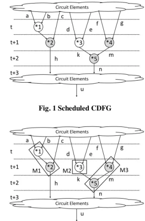
Fig. 1 Scheduled CDFG
Fig. 2 Functional Unit Binding for Testability
Figure 1 shows an example of a scheduled CDFG. In Fig. 1, operations appearing in white are operations with a test environment, and operations appearing in black are operations without a test environment. In Fig. 1, three multiplications are scheduled at the control step t+1. Hence, this scheduling requires three multipliers. On the other hand, the number of multiplications with a test environment is two. If the number of functional units required is greater than the number ofoperations with a test environment, then hierarchically untestable functional units are synthesized.
Figure 2 shows an example of functional unit binding for hierarchical testability. In Fig. 2, multiplications with a test environment are assigned to multipliers M1 and M2. Therefore, multipliers M1 and M2 are hierarchically testable functional units. On the other hand, multiplier M3 is hierarchically untestable because no multiplication with a test environment is assigned to M3.
The proposed binding method attempts to change hierarchically untestable functional units to hierarchically testable functional units by register binding. In order to achieve this goal, it is important that as many registers as possible can be assigned to the inputs and output of hierarchically untestable functional units. The proposed functional unit binding method intensively assigns operations without a test environment to hierarchically
Circuit Elements
Circuit Elements
a b c
d e
f g
n
u h
t t+1 t+2 t+3
*1
*3
*2 *4
k *5 m
Circuit Elements
Circuit Elements
a b c
d e f
g
k m
n
u h
t t+1 t+2 t+3
*1
*3
*2 *4
*5
M1 M2 M3
untestable functional units. As a result, the number of variables connected to hierarchically untestable functional units increases. Therefore, the number of registers that can be assigned to the inputs and output of hierarchically untestable functional units increases. In Fig. 2, the multiplication *5 without a test environment is able to be assigned to any multiplier. The proposed functional unit binding method intentionally assigns *5 to multiplier M3. As a result, the variables f, g, k, m, and n are connected to M3. Therefore, many variables are connected to M3, as compared to the case in which only *4 is assigned to M3.
D. Register Binding
The proposed register binding method attempts to change hierarchically untestable functional units to hierarchically testable functional units, which requires that the hierarchically untestable functional units satisfy properties 1 and 2 described in Section III-A.
In this paper, the input variables of an operation with a test environment are referred to as test pattern variables. The registers in which test pattern variables are assigned are referred to as test pattern registers. As a result of hierarchical test generation, it is guaranteed that any test pattern of functional units can be assigned to test pattern variables. In Fig. 2, variables a, b, d, and e are test pattern variables of the multiplications. The registers to which these variables are assigned are test pattern registers of the multiplier. The proposed register binding method can propagate test patterns to the inputs of hierarchically untestable functional units by register sharing between test pattern variables and the input variables of hierarchically untestable functional units. Furthermore, the proposed register binding method can detect fault effects at the output of hierarchically untestable functional units by register sharing between primary output variables and the output variables of hierarchically untestable functional units.
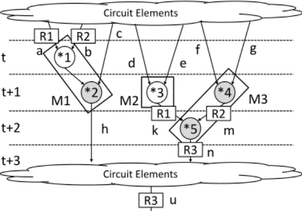
Fig. 3 Register Binding for Testability
Figure 3 shows an example of register binding for hierarchical testability based on functional unit binding results in Fig. 2. In Fig. 3, variables a and k are assigned to test pattern register R1. Furthermore, variables b and m are assigned to test pattern register R2. As a result, at control step t, test patterns for multiplier M1 are set to R1 and R2, and test patterns for M1 are also propagated to the inputs of M3. In Fig. 3, the variable u and primary output variable n are assigned to primary output register R3. As a result, output responses corresponding to the test patterns that are propagated to the inputs of M3 can be observed at the primary output of control step t+1. Thus, the proposed register binding method changes hierarchically untestable functional units to hierarchically testable functional units. However, if the multiplexers are connected to the inputs of M3, it is necessary to select the signals from R1 and R2 at control step t. Similarly, if the multiplexer is connected to the input of R3, it is necessary to select the signal from M3 at control step t. Furthermore, if R3 is a hold register, it is necessary for R3 to perform the load operation. Therefore, control signals of a controller synthesized by behavioral synthesis are modified.
IV. EXPERIMENTAL RESULTS
The experiments were performed using two example circuits to evaluate the effectiveness of the proposed method. In the experiments, hierarchical test generation using functional RTL circuits was performed for two circuits. In order to clarify the effectiveness of the binding method proposed herein, we compare two cases. In one case, the circuit is synthesized using the proposed method, and in the other case the circuit is synthesized without using the proposed method. Gate-level ATPG was also performed for the purpose of comparison with hierarchical test generation. The PICTHY C-based behavioral synthesis system was used for behavioral synthesis. Design CompilerTM from Synopsys was used for logic synthesis, and TetraMAXTM from Synopsys was used for fault simulation in hierarchical test generation, combinational test generation for each functional element, and sequential test generation at the gate level. All of the faults in the data path and the controller were evaluated in the experiments.
Table I shows the information of behavioral description for two example circuits. In Table I, the “Circuit” column indicates the name of circuit. The “#mult” column, the
“#add” column, and the “#sub” column list the number of multiplications, the number of additions, and the number of subtractions, respectively. The “Control statement used?” column indicates whether control statements are used in
M1 M2
Circuit Elements
Circuit Elements
a b
c
d e
f g
k m
n
u h
t t+1 t+2 t+3
*1
*3
*2 *4
*5
M3
R1 R2
R1 R2
R3
R3
behavioral description.
Table II shows the circuit synthesis results. In Table II, the
“Circuit” column indicates the name of the circuit, and the
“Proposed method used?” column indicates whether proposed method was applied. The “#REG” column lists the number of registers in the data path. The “#MUX” column lists the total number of inputs of the multiplexer. The “#FU” column lists the number of functional units. The
“#TESTABLE FU” column lists the number of hierarchically testable functional units. Finally, the “Area” column lists the circuit area after logic synthesis. In the experiments, the bit width of the data path was set to 32 bits.
The experimental results reveal that all functional units became hierarchically testable if the proposed method was used. In example 1, additional registers were needed to change all hierarchically untestable functional units into testable functional units, and hence the number of registers increased. On the other hand, in example 2, no additional registers were needed in order to change all hierarchically untestable functional units into testable functional units, and hence there is no increase in the number of registers. Table III shows the test generation results. In Table III, the
“Circuit” column indicates the name of the circuit, and the
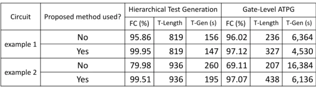
“Proposed method used?” column indicates whether proposed method was applied. The “Hierarchical Test Generation” column lists the results of hierarchical test generation using functional RTL circuits. The “Gate-Level ATPG” column lists the results of gate-level sequential ATPG by TetraMAXTM. The “FC” column lists the fault coverage. The “T-Length” column indicates the length of the test sequence. Finally, the “T-Gen” column indicates the test generation time.
In hierarchical test generation, the proposed method achieved highest fault coverage for examples 1 and 2. Furthermore, when the proposed method was applied, the fault coverage for test sequences generated by hierarchical test generation was improved by approximately 11.81% on average compared to the case in which the proposed method was not applied.
When the proposed method was applied, the fault coverage for test sequences generated by gate-level ATPG was improved by approximately 14.53% on average compared to the case in which the proposed method was not applied. Furthermore, test generation was approximately 2.04 times faster on average. Therefore, the proposed method is also effective for gate-level ATPG.
The hierarchical test generation method obtained test sequences approximately 41.53 times faster on average than
gate-level ATPG. The test generation time of the hierarchical test generation usually consists of the test environment generation time, the test sequence generation time, the functional elements ATPG time, and the fault simulation time. In the experiments, test environment generation and test sequence generation were applied through hand calculation. Therefore, the test environment generation time and the test sequence generation time were not included in the test generation time of the hierarchical test generation. However, these calculation times are expected to be a few seconds.
In hierarchical test generation, the proposed method achieved the best results in terms of both test generation time and fault coverage. Therefore, test design that combines hierarchical test generation using functional RTL circuits and the binding method for hierarchical testability proposed in this paper is effective for both test generation time and fault coverage.
V. CONCLUSION
This paper proposes a binding method for hierarchical testability using the hierarchical test generation results to achieve high fault coverage. By performing the proposed method, the fault coverage for test sequences generated by hierarchical test generation was improved by approximately 11.81% on average. Areas for future research include experiments involving large benchmark circuits and implementation of a binding method for hierarchical testability.
REFERENCES
[1] W. Kunz, and D. Pradhan, “Recursive Learning: An Attractive Alternative to the Decision Tree for Test Generation in Digital Circuits,” Proc. IEEE International Test Conference on Discover the New World of Test and Design, pp. 816-825, 1992.
[2] W. Kunz, and D. Pradhan, “Recursive Learning: An Attractive Alternative to the Decision Tree for Test Generation in Digital Circuits,” Proc. IEEE International Test Conference on Discover the New World of Test and Design, pp. 816-825, 1992.
[3] M. Henftling, H. C. Wittmann, and K. J. Antreich, “A Single-Path-Oriented Fault Effect Propagation in Digital Circuits Considering Multiple-Path Sensitization,” Proc. 1995 IEEE/ACM International Conference on Computer-Aided Design, pp. 304-309, 1995.
[4] C. Wang, S. Reddy, I. Pomeranz, X. Lin, and J. Rajski,
“Conflict driven techniques for improving deterministic test pattern generation,” Proc. IEEE International Conference on Computer-Aided Design, pp. 87-93, 2002.
[5] E. Gizdarski, and H. Fujiwara, “SPIRIT: A Highly Robust Combinational Test Generation Algorithm,” IEEE trans. on Computer Aided Design for Integrated Circuits and Systems, Vol. 21, No. 12, pp. 1446-1558, Dec. 2002.
[6] D. D. Gajski, N. D. Dutt, A. C.-H. Wu, and S. Y.-L. Lin, HIGH-LEVEL SYNTHESIS Introduction to Chip and
System Design, Kluwer Academic Publisher, 1992.
[7] I. Ghosh, and M. Fujita, “Automatic Test Pattern Generation for Functional RTL Circuits Using Assignment Decision Diagrams,” Proc. ACM/IEEE Design Automation Conference, pp. 43-48, June 2000.
[8] L. Zhang, I. Gosh, and M. Hsiao, “Efficient Sequential ATPG for Functional RTL Circuits,” Proc. International Test Conference, pp. 290-298, Sept. 2003.
[9] H. Fujiwara, C. Y. Ooi, and Y. Shimizu, “Enhancement of Test Environment Generation for Assignment Decision Diagrams,” 9th IEEE Workshop on RTL and High Level Testing (WRTLT’08), pp. 45-50, Nov. 2008.
[10] S. Bhatia, and N. K. Jha, “Integration of Hierarchical Test Generation with Behavioral Synthesis of Controller and Data Path Circuits,” IEEE trans. on Very Large Scale Integration Systems, Vol. 6, No. 4, Dec. 1998.
[11] T. Hosokawa, H. Fujiwara, R. Inoue, and H. Fujiwara, “A Binding Method for Hierarchical Testing Using Results of Test Environment Generation,” 12th IEEE Workshop on RTL and High Level Testing (WRTLT’11), pp. 16-22, Nov. 2011. [12] V. Chaiyakul, D. D. Gajski, and L. Ramachandran,
“High-Level Transformations for Minimizing Syntactic Variances,” proc. Design Automation Conference, pp. 413-428, June 1993.
Table I Circuit Information
Table II Circuit Synthesis Results
Table III Test Generation Results
Circuit #mult #add #sub
Control statement used?example1
7 0 3 No
example2
6 6 0 Yes (if-else)
Circuit Proposed method used? #REG #MUX #FU #TESTABLE FU Area
example 1
No 6 32 5 3 25,401
Yes 7 31 5 5 25,662
example 2
No 6 39 5 2 25,736
Yes 6 37 5 5 25,643
Circuit Proposed method used?
Hierarchical Test Generation Gate-Level ATPG FC (%) T-Length T-Gen (s) FC (%) T-Length T-Gen (s)
example 1 No 95.86 819 156 96.02 236 6,364
Yes 99.95 819 147 97.12 327 4,530
example 2 No 79.98 936 260 69.11 207 16,384
Yes 99.51 936 195 97.07 438 6,136