Acceleration of Transition Test Generation for Acyclic Sequential Circuits
Utilizing Constrained Combinational Stuck-at Test Generation
Tsuyoshi Iwagaki Satoshi Ohtake Hideo Fujiwara
Graduate School of Information Science, Nara Institute of Science and Technology Kansai Science City 630-0192, Japan
E-mail:{tsuyo-i, ohtake, fujiwara}@is.naist.jp Abstract
This paper presents a transition test generation method for acyclic sequential circuits. In this method, to gener- ate test sequences for transition faults in a given acyclic sequential circuit, constrained combinational stuck-at test generation is performed on its double time-expansion model that is composed of two copies of a time-expansion model of the given circuit. This method is complete, i.e., this method can generate test sequences for all the testable tran- sition faults and can identify all the untestable transition faults in a given acyclic sequential circuit. Experimental results show that our method can achieve higher fault ef- ficiency with drastically shorter test generation time than that achieved by a conventional method.
1 Introduction
Test generation for sequential circuits is generally a hard problem. In performing test generation for a sequential cir- cuit, huge computation time is required to identify sequen- tially untestable faults. It is impossible to identify all the sequentially untestable faults in a large circuit. To perform test generation for sequential circuits efficiently, a concept of software transformation [1] has been proposed. Simi- larly, a concept of circuit pseudo-transformation (CPT) [2] has been proposed as a more general concept. The CPT is tentatively performed only during test generation to trans- form a given sequential circuit into a different circuit whose tests can be generated more easily. Several test genera- tion methods based on this concept have been proposed for stuck-at faults [3, 4, 5, 6, 7, 8] and delay faults [9, 10].
For the stuck-at fault model, balanced structure has been proposed as an easily testable circuit structure [3]. The stuck-at fault testability of a balanced sequential circuit is preserved in its combinationally equivalent circuit. That is, test sequences for all the testable stuck-at faults in a balanced sequential circuit can be generated, and all the untestable stuck-at faults in the circuit can be identified by applying a combinational stuck-at fault test generation algo-
rithm (ATPG) to its combinationally equivalent circuit. Test generation methods for acyclic sequential circuits, which are a super class of balanced sequential circuits, have been proposed [4, 6, 8]. To generate test sequences for a given acyclic sequential circuit, these methods use a transformed combinational circuit in which the function and timing be- havior of the given circuit are simulated. Under the CPTs used in [4, 6, 8], the stuck-at fault testability of an acyclic sequential circuit is also preserved in its transformed com- binational circuit.
Similarly, for the delay fault model, two test generation methods based on CPT have been proposed [9, 10]. In [9], it was shown that the delay fault testability of a balanced se- quential circuit is preserved in its combinationally equiva- lent circuit. For an acyclic sequential circuit, unlike the case of the stuck-at fault model, a sequential delay fault ATPG is required to generate test sequences [11]. This implies that it is hard to achieve high fault efficiency with short test gener- ation time. In [10], we showed that the delay fault testability of an acyclic sequential circuit is not preserved in its time- expansion model [6]. Moreover, we proposed a subclass of acyclic sequential circuits whose delay fault testability is preserved in its time-expansion model. The circuit struc- ture is called discontinuous reconvergence (DR) structure. In consequence of restricting circuit structure, we can use a combinational delay fault ATPG.
For stuck-at faults and delay faults, partial scan tech- nique and partially enhanced scan technique can be used as straightforward methods to apply the above test genera- tion methods based on CPT to a general sequential circuit, respectively. Given a sequential circuit, in partial scan tech- nique, some flip-flops (FFs) are replaced by scan FFs such that its kernel, which is the circuit excluding the scan path, become a desired circuit structure. In partially enhanced scan technique, enhanced scan FFs [12] are used instead of scan FFs. Hardware overheads in these design methods depend on which circuit structure is used for a kernel. If acyclic structure is used for a kernel, its hardware overhead is the smallest of the circuit structures mentioned above.
In this paper, we present a transition test generation method for acyclic sequential circuits. In this method, to 10th IEEE European Test Symposium (ETS '05) , pp. 48-53, May 22-25, 2005.
1
3
5 4
6
2
8
7
PI2
PI3 PI5
PI6
PO2 PO1
PO3
PI4 PI1
: FF : CLB
l
Figure 1: Acyclic sequential circuit: S generate tests for transition faults in a given acyclic sequen- tial circuit, constrained combinational stuck-at test genera- tion is performed on its double time-expansion model that is composed of two copies of a time-expansion model of the given circuit. That is, unlike the method proposed in [10], we do not restrict circuit structure but modify its test gen- eration model for a given acyclic sequential circuit. As a result, an increase of hardware overhead is not incurred. This method is complete, i.e., this method can generate tests for all the testable transition faults, and can identify all the untestable transition faults. We show that, by some experi- ments, our method can achieve higher fault efficiency with drastically shorter test generation time than that obtained by a conventional sequential test generation method.
2 Preliminaries
2.1 Target Circuit and Fault Model
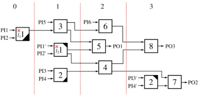
A sequential circuit generally consists of combinational logic blocks (CLBs) connected with each other directly or through FFs. A CLB is a region of connected combinational logic gates. This paper targets acyclic sequential circuits in which there is no cyclic path. For example, an acyclic se- quential circuit S is shown in Figure 1. In this paper, we as- sume that FFs are of D-type. This assumption does not im- pose restrictions on circuit representation because the other types of FFs can be modeled by a D-type FF and some logic gates. Note that although a general sequential circuit is not acyclic, the circuit can be made acyclic by using some tech- niques, e.g., enhanced scan technique.
Our target faults are transition faults in acyclic sequen- tial circuits. There are two transition faults associated with each line in an acyclic sequential circuit: a slow-to-rise fault and a slow-to-fall fault. Under the transition fault model, the extra delay caused by a transition fault is assumed to be large enough to prevent the transition through the faulty site from reaching any FF or any primary output within a specified time. In this paper, it is assumed that transition faults in acyclic sequential circuits are tested in the slow- fast-slow testing manner [13]. Under this assumption, we can consider a sequential circuit to be delay fault-free in both the fault initialization and the fault effect propagation. Note that if a transition fault is testable under the at-speed testing manner, the fault is also testable under the slow-fast-
1 3
5 4 6
2 8
7 2
PI1 1
PI1'
PI3' PI3
PI2'
PI4
PI5 PI6
PI4' PI2
PO2
PO1 PO3
0 1 2 3
l1
l2
Figure 2: Time-expansion model of S: C(S) slow testing manner [13]. Hence, the slow-fast-slow testing never misses any testable fault in the at-speed testing. 2.2 Time-Expansion Model
In this subsection, we mention a time-expansion model (TEM) [6], which is used in our test generation method. Then, we describe the correspondence between a transition fault in an acyclic sequential circuit and a transi- tion fault in its TEM. We also explain the correspondence between a two-pattern test for a TEM and a test sequence for its original circuit.
A TEM of a given acyclic sequential circuit is a combi- national circuit in which the function and timing behavior of the given circuit are simulated. Figure 2 is a TEM C(S) of the circuit S shown in Figure 1. TEM C(S) is a combina- tional circuit derived by connecting CLBs according to their sequential depths. A sequential depth between two CLBs is defined as the number of FFs on a path between them. If a CLB has paths to another CLB in S whose sequential depths are different, the CLB is duplicated in C(S). For ex- ample, in Figure 1, since CLB 1 has two paths to CLB 5 whose sequential depths (one and two) are different, CLB 1 is duplicated in C(S) (Figure 2). A shaded part of a CLB in Figure 2 represents a portion of the lines and gates re- moved. There is no path from the portion to any input of CLBs or any primary output of C(S). The number placed at the top of each column in Figure 2 is the label of CLBs in the column. The label of a CLB v is denoted as t(v).
A transition fault in an acyclic sequential circuit is mapped into a single or a multiple transition fault in its TEM. For example, a transition fault associated with a line l in CLB 1 of S (Figure 1) is mapped into a multiple fault whose respective faults exist in the duplicated CLBs of C(S) (Figure 2) if the corresponding lines l1, l2are not removed. Note that since we use the slow-fast-slow testing manner during test application, we can handle respective transition faults in a multiple transition fault one by one.
Here, we briefly describe how a two-pattern test for a TEM is transformed into a test sequence for its original circuit. A two-pattern test for a TEM is transformed into a test sequence for its original circuit on the basis of the information about the label of each primary input in the TEM. For example, suppose that a two-pattern test for C(S)
Table 1: Input and output sequences
Time 0 1 2 3 4
PI1 vPI11 vPI12 = v1PI1! vPI12 ! X X PI2 vPI21 vPI22 = v1PI2! vPI22 ! X X PI3 X vPI31 vPI32 vPI31 ! vPI32 ! PI4 X vPI41 vPI42 vPI41 ! vPI42 !
PI5 X vPI51 vPI52 X X
PI6 X X vPI61 vPI62 X
PO1 X X vPO11 vPO12 X
PO2 X X X vPO21 vPO22
PO3 X X X vPO31 vPO32
shown in Figure 2: PI1= (vPI11 , vPI12 ), PI2 = (vPI21 , vPI22 ), PI1!= (vPI11 !, vPI12 !), PI2!= (v1PI2!, vPI22 !), PI3 = (vPI31 , vPI32 ), PI4= (vPI41 , vPI42 ), PI5 = (vPI51 , vPI52 ), PI6 = (vPI61 , vPI62 ), and the corresponding responses: PO1= (vPO11 , vPO12 ), PO2 = (vPO21 , vPO22 ), PO3 = (vPO31 , vPO32 ), are given. From the la- bel information of C(S), if vPI12 = vPI11 ! and vPI22 = vPI21 !, this two-pattern test is transformed into the test sequence for S (Figure 1) shown in Table 1. The above transformation is formally defined in [10].
3 Proposed Method
3.1 Motivation and Main Ideas
As shown in Table 1, we can obtain a test sequence for an acyclic sequential circuit only if, for its TEM, the first vector of a primary input u and the second vector of a primary input v such that t(u)−t(v) = 1 and l(u) = l(v) are the same value, where l(u) = l(v) means that u and v are identical in the original circuit. This limitation is induced by the fact that a TEM of an acyclic sequential circuit does not include information about its pattern dependency such as vPI12 = vPI11 ! and vPI22 = vPI21 ! in Table 1. Thus, it is not sufficient to use only a TEM to generate test sequences for its original circuit that is acyclic.
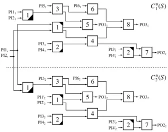
In order to generate transition tests for an acyclic sequen- tial circuit, we define the following test generation model that includes information about its pattern dependency. Definition 1 Let S be an acyclic sequential circuit, and C(S) be a TEM of S. Then, a combinational circuit ob- tained by the following procedure is said to be a double time-expansion model (DTEM) C∗(S) of S.
S1: Make two copies of C(S): C1∗(S), C2∗(S).
S2: Connect any pair of primary inputs u in C1∗(S) and v in C2∗(S) such that t(u) − t(v) = 1 and l(u) = l(v) with each other, and feed a new primary input w into them.
! Figure 3 shows a DTEM C∗(S) of S (Figure 1). In Fig- ure 3, C∗(S) is composed of two copies of C(S) (Figure 2): C∗1(S), C∗2(S), and PI1sand PI2sare created according to S2 of Definition 1. A single pattern for C∗1(S) (resp. C2∗(S))
C*2(S)
C*1(S)
1 3
5 4 6
2 8
7 2
1
PI1'2
PI3'2
PI32
PI2'2
PI42
PI52 PI62
PI4'2
PO22
PO12 PO32
1 3
5 4 6
2 8
7 2
PI11 1
PI3'1
PI31
PI41
PI51 PI61
PI4'1
PI21
PO21
PO11 PO31
PI1s
PI2s
Figure 3: Double time-expansion model of S: C∗(S) corresponds to the first (resp. second) vector of a vector pair for C(S). Note that, in Figure 3, a single pattern for PI1sand PI2scorresponds to both the second vector for PI1 and PI2 and the first vector for PI1!and PI2!in Figure 2.
Transition test generation is similar to stuck-at test generation. A two-pattern test (V1,V2) for the slow-to- rise (resp. slow-to-fall) fault associated with a line l in a combinational circuit has the following two properties:
1. the value of 0 (resp. 1) is justified to l by V1, and 2. the stuck-at 0 (resp. 1) fault associated with l is de-
tected by V2.
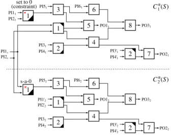
According to these properties, we can generate the first vec- tor and the second vector of a two-pattern test separately. Here, let us consider applying the above properties to a DTEM. We can generate a two-pattern test for the slow- to-rise (resp. slow-to-fall) fault associated with a line l in a TEM C(S) by performing stuck-at test generation for the stuck-at 0 (resp. 1) fault associated with a corresponding line l2 in C2∗(S) under the following constraint: the value of the corresponding line l1 in C∗1(S) is set to 0 (resp. 1). For example, in order to generate a two-pattern test for the slow-to-rise fault associated with a line l1 in CLB 1 (Fig- ure 2), we perform stuck-at test generation for the DTEM with a constraint shown in Figure 4. From the above dis- cussion, we see that a test sequence for a transition fault in an acyclic sequential circuit can be generated by perform- ing constrained combinational stuck-at test generation on its DTEM.
The correctness of the above test generation is guaran- teed by the following theorem.
Theorem 1 Let S and C∗(S) be an acyclic sequential circuit and a DTEM of S, respectively. Let ftS be the slow-to-rise (resp. slow-to-fall) fault associated with a line l in S. Let FC
∗(S)
s be the set of stuck-at 0 (resp. 1) faults associated with the set of lines L2in C2∗(S) corresponding to l. Then, (i) ftS is testable if and only if at least one fC
∗(S)
s ∈FC
∗(S) s
s-a-0 set to 0 (constraint)
C*2(S)
C*1(S)
1 3
5 4 6
2 8
7 2
1
PI1'2
PI3'2
PI32
PI2'2
PI42
PI52 PI62
PI4'2
PO22
PO12 PO32
1 3
5 4 6
2 8
7 2
PI11 1
PI3'1
PI31
PI41
PI51 PI61
PI4'1
PI21
PO21
PO11 PO31
PI1s
PI2s
Figure 4: Double time-expansion model with a constraint
associated with l2∈L2is testable under the following con- dition:
• an objective (0, l1) (resp. (1, l1)) in C1∗(S) must be sat- isfied, i.e., the value of 0 (resp. 1) has to be justified to l1in C∗1(S), where l1is the line corresponding to l2. Furthermore, (ii) a test pattern generated for fC
∗(S) s can al- ways be transformed into a test sequence for ftS.
Sketch of proof: We demonstrate (i) of Theorem 1 first. Under the slow-fast-slow testing manner, we can treat stuck-at faults in FC
∗(S)
s one by one. Hence, it is sufficient to consider whether at least one fC
∗(S)
s is testable. The transi- tion fault testability of S is not preserved in C(S) [10]. This is because C(S) does not include information about the pat- tern dependency in S. Unlike C(S), C∗(S) includes informa- tion about the pattern dependency. Consequently, C∗(S) can simulate the function and timing behavior of S. By a similar discussion in [10], (i) of Theorem 1 can be demonstrated.
Then, we can easily see that (ii) of Theorem 1 is true because C∗(S) includes information about the pattern de-
pendency in S. !
3.2 Test Generation Procedure
All the testable transition faults can be tested, and all the untestable transition faults can be identified by performing test generation based on only Theorem 1. In order to per- form test generation more efficiently, we propose the fol- lowing test generation procedure. In the following proce- dure, for the sake of efficiency, we make use of the fact that a necessary condition to detect the transition fault as- sociated with a line is that the corresponding stuck-at fault on the line is detectable. That is, we perform stuck-at test generation for a TEM of a given acyclic sequential circuit, then construct vector pairs for transition faults in the TEM from test patterns for stuck-at faults. This additional step
aims to detect many transition faults before performing test generation based on Theorem 1.
Given an acyclic sequential circuit S, our method is per- formed as follows.
Main Procedure
S1: Create a transition fault list FtSof S.
S2: Construct a TEM C(S) of S and a DTEM C∗(S) of S. S3: Perform a sub procedure FAULT DROPPING.
Until FtSis empty, iterate S4.
S4: For each remaining fault in FtS, the following steps are performed.
(a): Perform test generation based on Theorem 1. (b): Convert a test pattern tC
∗(S)
s generated in S4(a) into a two-pattern test tC(S)t for C(S).
(c): Perform transition fault simulation by applying ttC(S)to C(S).
(d): Add ttC(S)to TtC(S).
(e): Drop all the corresponding transition faults de- tected in S4(c) from FtS.
S5: Convert TtC(S)into a transition test set TtSfor S. Sub ProcedureFAULT DROPPING
(a): Create a stuck-at fault list FsC(S)of C(S).
(b): Generate a stuck-at test set TsC(S)for FsC(S)by using a combinational stuck-at fault ATPG.
(c): Convert TsC(S)into a vector pair set VtC(S)for C(S). (d): Perform transition fault simulation by applying VtC(S)
to C(S).
(e): Add valid vector pairs, which detect some transition faults in (d), to a transition test set TtC(S)for C(S). (f): Drop all the corresponding transition faults detected
in (d) from FtS.
Here, we explain some steps in the above procedure in detail. In S3(b), stuck-at test generation is performed. As mentioned above, a necessary condition to detect the tran- sition fault associated with a line is that the correspond- ing stuck-at fault on the line is detectable. Hence, if all the stuck-at faults corresponding to a transition fault in S are identified as untestable, the transition fault is also untestable. This step is useful in achieving efficient test generation. Note that, for a given sequential circuit, if stuck- at fault testing is performed by using the method proposed in [6] in advance, TsC(S) can be obtained without perform- ing test generation in S3(b). In S3(c), we convert TsC(S)
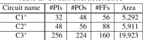
Table 2: Circuit characteristics Circuit name #PIs #POs #FFs Area
C1∗ 32 48 56 5,292
C2∗ 48 56 88 5,911
C3∗ 256 224 160 19,923
into VtC(S) for C(S) such that pattern conflict does not oc- cur. During pattern conversion, each first vector in VtC(S)is basically derived by complementing its corresponding pat- tern in TsC(S), which is the second vector, such that a tran- sition occurs. In [14], Liu et al. have proposed an efficient method to obtain two-pattern tests for transition faults from given test patterns for stuck-at faults. If one wants to con- struct two-pattern tests more efficiently, this method could be used in S3(c) with some modification. In S4, if all the du- plicated stuck-at faults corresponding to a transition fault in the original circuit are identified as untestable, the transition fault is also untestable. Note that if one of all the duplicated stuck-at faults corresponding to a transition fault in the orig- inal circuit is detected, we do not need to consider the other duplicated faults. Although, in this step, we need to per- form test generation under constraints, commercial ATPG tools can usually support such kind of constraints.
4 Experimental Results
In this section, we evaluate the proposed method in terms of hardware overhead, test generation time, test application time and fault efficiency.
The following experiment was carried out on a Sun Blade 2000 workstation. To perform test generation and fault simulation, TetraMAX ATPG (Synopsys) was used as a combinational and sequential ATPG tool with a back- track limit of 100. We used acyclic versions of the circuits reported in [10]. The characteristics of these circuits are shown in Table 2. In Table 2, columns “#PIs”, “#POs” and
“#FFs” denote the number of primary inputs, primary out- puts and FFs, respectively. Column “Area” denotes the area of a circuit estimated by Design Compiler (Synopsys). The area of a 2-input NAND gate was considered to be 2.
First, we evaluate the hardware overhead needed to make a given circuit acyclic by using enhanced scan technique. The result of hardware overheads reported in [10] shows that, by using acyclic structure as a kernel structure, an about 9.5% reduction on average (a 11.2% reduction in the best case) was achieved compared with the case of using DR-structure. Thus, our method is effective in hardware overhead compared to the previous method.
Next, we show the test generation results. Table 3 lists the test generation results obtained by sequential test gener- ation for transition faults in the respective circuits, denoted by “Sequential ATPG”, and by our proposed test generation procedure, denoted by “Our method”. Columns “#faults”,
“#det”, “#unt” and “#abt” give the number of target transi- tion faults, detected faults, identified untestable faults and
aborted faults, respectively. Columns “TGT [s]”, “FE [%]” and “TAT [clock cycles (CC)] denote test generation time which includes fault simulation time, fault efficiency and test application time, respectively. The fault efficiency is defined as 100 ×(#det + #unt)/#faults. The test application time of our method is calculated by (d + 1) · nTPT, where nTPTis the number of generated two-pattern tests and d is the maximum sequential depth of a given acyclic sequential circuit. In the conventional method (“Sequential ATPG”), the test application time is the length of a generated test sequence. Note that we do not consider scan shift opera- tion here. From Table 3, we can see that our method out- performed the conventional method in test generation time as well as fault efficiency. In the best case, our method achieved 15.09% higher fault efficiency with about 82 times faster test generation speed than that of the conventional method. Table 3 also shows our method resulted in long test application time compared to that of the conventional method. However, it should not be viewed as a serious problem. This is because our method detected more faults compared with the conventional method. Furthermore, if we use the method reported in [15], we can reduce the test application time.
Finally, we analyze the effectiveness of S3 (FAULT DROPPING) of our method. Table 4 shows the results of performing the normal flow of our method and the flow without S3. From Table 4, we see that S3 can work well for all the aspects of test generation, especially for test application time.
5 Conclusions and Future Work
In this paper, we presented a transition test generation method for acyclic sequential circuits. In this method, to generate test sequences for transition faults in a given acyclic sequential circuit, constrained combinational stuck- at test generation is performed on its double time-expansion model that is composed of two copies of a time-expansion model of the given circuit. This method can generate test sequences for all the testable transition faults and can iden- tify all the untestable transition faults in a given acyclic sequential circuit. In this paper, on the basis of circuit pseudo-transformation (CPT), we accelerated test genera- tion. Moreover, the CPT made the use of an efficient pro- cedure such as FAULT DROPPING possible. We showed that our method is effective in test generation time, fault ef- ficiency and hardware overhead by experiments.
Our future work is to extend the proposed method to be able to handle the path delay fault model.
Acknowledgments
We would like to thank Prof. Michiko Inoue, Dr. Tomokazu Yoneda, Dr. Thomas Clouqueur and Ms. Chia Yee Ooi of Nara Institute of Science and Tech- nology for their useful comments. We also would like to thank Prof. Tomoo Inoue of Hiroshima City University for
Table 3: Test generation results
Circuit name Method #faults #det #unt #abt TGT [s] FE [%] TAT [CC]
C1∗ Sequential ATPG
12,238 11,724 26 488 131.45 96.01 487
Our method 12,194 41 3 6.76 99.98 1,190
C2∗ Sequential ATPG
13,016 10,898 23 2,095 1,122.03 84.01 221
Our method 12,873 26 117 13.76 99.10 1,008
C3∗ Sequential ATPG
48,032 43,658 0 4,874 4,709.04 90.91 189
Our method 45,885 0 2,147 195.40 95.53 1,737
Table 4: Effectiveness of S3 (FAULT DROPPING) Circuit name Flow TGT [s] FE [%] TAT [CC]
C1∗ Without S3Normal 31.856.76 99.9899.98 1,1908,310 C2∗ Without S3Normal 13.7610.22 99.1097.98 1,0082,200 C3∗ Without S3Normal 195.40248.37 95.5393.75 1,7376,462 his helpful suggestions. This work was supported in part by
JSPS (Japan Society for the Promotion of Science) under Grants-in-Aid for Scientific Research B(2) (No. 15300018). References
[1] A. Balakrishnan, S.T. Chakradhar, “Software transforma- tions for sequential test generation,” Proc. IEEE 4th Asian Test Symp., pp. 266–272, Nov. 1995.
[2] S. Ohtake, T. Inoue and H. Fujiwara, “Sequential test gen- eration based on circuit pseudo-transformation,” Proc. IEEE 6th Asian Test Symp., pp. 62–67, 1997.
[3] R. Gupta, R. Gupta and M. A. Breuer, “The BAL- LAST methodology for structured partial scan design,” IEEE Trans. on Computers, Vol. 39, No. 4, pp. 538–544, Apr. 1990.
[4] A. Kunzmann and H.-J. Wunderlich, “An analytical ap- proach to the partial scan problem,” Journal of Electronic Testing: Theory and Applications, Vol. 1, No. 2, pp. 163– 174, May 1990.
[5] A. Balakrishnan and S. T. Chakradhar, “Sequential circuits with combinational test generation complexity,” Proc. 9th Int. Conf. on VLSI Design, pp. 111–117, Jan. 1996. [6] T. Inoue, T. Hosokawa, T. Mihara and H. Fujiwara, “An op-
timal time expansion model based on combinational ATPG for RT level circuits,” Proc. 7th Asian Test Symp., pp. 190– 197, 1998.
[7] H. Fujiwara, “A new class of sequential circuits with combi- national test generation complexity,” IEEE Trans. on Com- puters, Vol. 49, No. 9, pp. 895–905, Sep. 2000.
[8] Y. C. Kim, V. D. Agrawal and K. K. Saluja, “Combinational test generation for various classes of acyclic sequential cir- cuits,” Proc. Int. Test Conf., pp. 1078–1087, 2001.
[9] S. Ohtake, S. Miwa and H. Fujiwara, “A method of test gen- eration for path delay faults in balanced sequential circuits,” Proc. 20th IEEE VLSI Test Symp., pp. 321–327, 2002. [10] T. Iwagaki, S. Ohtake and H. Fujiwara, “Reducibility of
sequential test generation to combinational test generation for several delay fault models,” Proc. IEEE 12th Asian Test Symp., pp. 58–63, 2003.
[11] T. J. Chakraborty, V. D. Agrawal and M. L. Bushnell, “Im- proving path delay testability of sequential circuits,” IEEE Trans. VLSI Systems, Vol. 8, No. 6, pp. 736–741, Dec. 2000. [12] Y. K. Malaiya and R. Narayanaswamy, “Testing for timing faults in synchronous sequential integrated circuits,” Proc. Int. Test Conf., pp. 560–571, 1983.
[13] A. Krsti´c and K.-T. Cheng, Delay fault testing for VLSI cir- cuits, Kluwer Academic Publishers, 1998.
[14] X. Liu, M. S. Hsiao, S. Chakravarty and P. J. Thadikaran,
“Efficient transition fault ATPG algorithms based on stuck- at test vectors,” Journal of Electronic Testing: Theory and Applications, Vol. 19, No. 4, pp. 437–445, Aug. 2003. [15] T. Hosokawa, T. Inoue, T. Hiraoka and H. Fujiwara, “Static
and dynamic test sequence compaction methods for acyclic sequential circuits using a time expansion model,” Proc. 8th IEEE Asian Test Symp., pp. 192–199, 1999.
[16] M. Abadir and J. Zhu, “Transition test generation us- ing replicate-and-reduce transform for scan-based designs,” Proc. 21st VLSI Test Symp., pp. 22–27, 2003.
[17] T. Iwagaki, S. Ohtake and H. Fujiwara, “Equivalence of se- quential transition test generation and constrained combina- tional stuck-at test generation,” Technical Report of IEICE, Vol. 104, No. 664, pp. 27-32, Feb. 2005.