A dissertation submitted for the degree of Doctor of Philosophy
Study on Soil-Screw Interaction of Exploration Robot
for Surface and Subsurface Locomotion in Soft Terrain
February 2011
by
Kenji Nagaoka
Department of Space and Astronautical Science
School of Physical Sciences
The Graduate University for Advanced Studies (Sokendai)
JAPAN
Acknowledgment
At completing this dissertation, I would like to extend my gratitude to all the people regarding my research activity over the past five years.
Above all, I would like to express my deepest gratitude for my PI, Professor Takashi Kubota. He has always encouraged me to aspire for getting my doctoral degree during research life at the ISAS. I could pursue my studies and enhance my humanity under his distinguished direction. Words cannot describe my gratitude for him.
I would also like to extend my sincere gratitude to my supervisor, Professor Satoshi Tanaka. His suggestions and scientific knowledge brought a different perspective to my research.
I wish to express my gratitude for Professor Ichiro Nakatani, Professor Tatsuaki Hashimoto, Professor Tetsuo Yoshimitsu, Professor Shin-ichiro Sakai, Professor Nobutaka Bando, Professor Masatsugu Otsuki, Dr. Andrew Klesh and Dr. Genya Ishigami. Through my seminar presenta- tions or individual discussions, their valuable suggestions enabled to cultivate my research. In particular, Professor Otsuki helped me conduct various experiments, and he gave me numerous advices in this five years. Without his continual support, I could not complete my dissertation.
I would like to sincerely appreciate Ms. Mayumi Oda, the secretary of the Kubota lab. Her helps allowed me to do my research smoothly. Also, I wish to give my special thanks to my labmates and great alumnae/alumni. Life in the lab with them were very precious to me, and I thank them for having such productive days.
I acknowledge for Shimizu-Kikai, especially President Hideki Yamazaki. His supports and advices enabled me to accomplish this study.
I greatly appreciate Mr. Eijiro Hirohama and Ms. Takemi Chiku, the stuff of the JAXA Space Education Center in 2008. Thanks to their graceful supports, I had participated the NASA Academy 2008 at the NASA Goddard Space Flight Center. That summer was definitely a very pleasurable time for me, and I could lean and experience countless things during the project.
I also express my appreciation all the members of the ISAS football club. The daily exercise with them gives momentary happiness to my hectic life.
Last of all, I am deeply grateful for my parents, Yoshiaki and Junko.
January 31, 2011 Kenji Nagaoka
Abstract
This dissertation addresses an interaction between an Archimedean screw mechanism and soil for surface and subsurface locomotion in soft terrain based on experimental and theoretical analyses. The main objective of this research is understanding of an unknown soil-screw inter- action. This research is expected to contribute to an application of a helical screw mechanism to unmanned exploration robots and automated machineries. The screw mechanism elaborated in this dissertation has been an attractive device that enables both traveling (subsurface loco- motion) and drilling (subsurface locomotion) in the soft terrain since ancient times. On the other hand, an approach to the interaction has not been enterprisingly discussed because of smooth machine operation by human supports on ground. To accomplish unmanned and au- tonomous robotic excavation and locomotion on unknown extraterrestrial surfaces, however, it is required to clarify and systematize the interaction. Explicitly considering deformability, fail- ure and nonuniformity of terrains, this research attempts to theorizes the interaction based on not only mechanical dynamics but also soil mechanics and geotechnique. Further, this disser- tation elaborates the soil-screw interaction by discussing surface and subsurface locomotion. The surface and the subsurface locomotion make a difference in their propulsive directions to direction of gravitational force. In addition, anisotropical constraints by surrounding soils can generally be assumed around a robot in the surface locomotion. Meanwhile, the subsurface one is governed by isotropical constraints of contact with the soils. The constraints also distribute three-dimensionally. Therefore, interactive mechanics between the screw and the soil differs in each locomotion environment. In this dissertation, the undissolved interaction is elaborated through synthetic discussions of the surface and the subsurface locomotion.
With respect to the surface locomotion, a traveling method by using the Archimedean screw devices is proposed as a new locomotion technique on soft soil. Generally, soil contact reacting on such screw anisotropically distributes. Thus modeling of the complicated contact state be- comes a key factor. This dissertation first describes that proposed screwed locomotion method is robust to getting stuck, which is a critical issue for conventional wheeled locomotion. Accord- ing to this, validity of traveling by the screw on soil is indicated by comparison with a wheel and a track. Then, this research attempts to derive the soil-screw interaction models based on skin friction and terramechanics (soil compression and failure). The simulation analyses of the models show better trafficability and maneuverability of the proposed system. Furthermore, ma- neuverability experiments were carried out by using a new prototyped robot equipped with dual
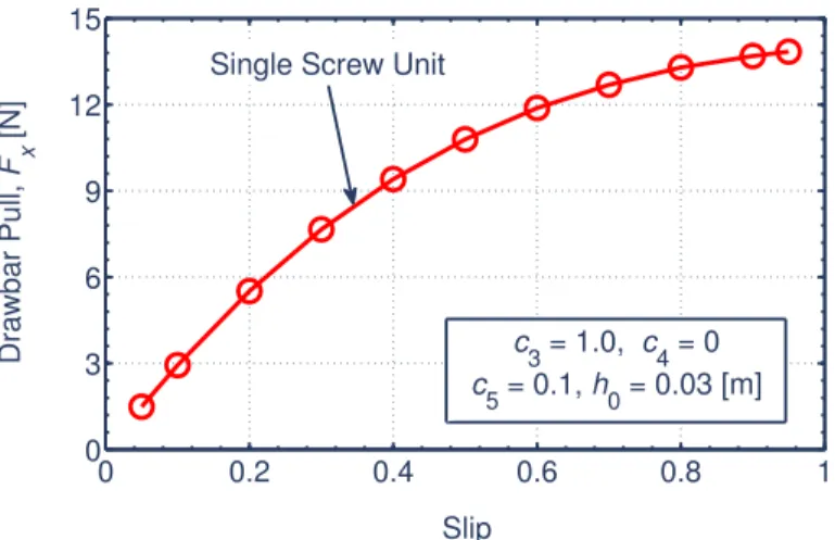
Archimedean screw units on sand. Through the laboratory tests, it is confirmed that various maneuvers can be achieved by changing rotational speed of each screw. Summarizing the re- sulted maneuvers, directions of propulsive force that the prototyped robot exerts are presented. In addition to these tests, trafficability tests of a single screw unit were conducted in sandy ter- rain to comprehend its characteristics of drawbar pull and slip. The experimental results provide qualitative analyses of the drawbar pull, and thereby the interaction can be discussed. Based upon these considerations, this dissertation indicates applicability and feasibility of the screw mechanism for the surface locomotion on the soft terrain.
With respect to the subsurface locomotion, this dissertation proposes a subsurface drilling robot using the Archimedean screw mechanism. Prior to detailed discussion of the interaction, this dissertation describes an advantage of a subsurface explorer. Moreover, this research qual- itatively organizes how a robot achieve drilling motion in complicated subsurface environment. In accordance with this remark, this dissertation indicates effectiveness of the screw mechanism for the subsurface drilling. Then, a novel interaction model between the screw and the surround- ing soils is proposed based on soil mechanism with screw geometry. In the interaction modeling, by applying cavity expansion theory, the proposed model includes an increase of soil pressure caused by laterally compressing subsoil. The validity of the model is discussed through experi- mental analyses. Consequently, the model enables to calculate required torque of the screw with depth. The result is expected to lead not only to understanding of the interaction but also to de- sign optimization of screw geometry. Furthermore, an effective screw mechanism (Contra-rotor Screw Drilling mechanism) is proposed to achieve an efficient self-drilling. The new mechanism is experimentally investigated, and thereby its feasibility and proper conditions are indicated.
In this dissertation, the unknown soil-screw interaction of the Archimedean screw mechanism in the soft terrain is addressed from the standpoints of the surface and the subsurface locomotion. So far, studies on theoretical approaches of the practical application of such screw mechanism have been particularly limited although it is an interesting and useful tool for the locomotion. Therefore, this research is expected to provide an initiative of the screw mechanism. This re- search fosters the understanding of the complicated soil-screw interaction by discussing the applications in the surface and subsurface locomotion. Additionally, this dissertation makes a significant contribution in the field of general screw mechanism and leads to the design optimiza- tion and the motion control. The developed ideas can cover applications of manned/unmanned activities on Earth.
Contents
Chapter 1. Introduction 1
1.1 Background . . . 1
1.2 Motivation . . . 3
1.2.1 Requirements for Space Robotics . . . 3
1.2.2 Applicability of Archimedean Screw Mechanism . . . 3
1.3 Purpose and Approach . . . 4
1.4 Research Contributions. . . 6
1.5 Outline . . . 6
Chapter 2. Archimedean Screw Mechanism 11 2.1 Geometric Modeling of Screw Mechanism . . . 11
2.1.1 Screw Slope Parameter. . . 12
2.1.2 Screw Pitch . . . 13
2.1.3 Screw Surface Area . . . 14
2.1.4 Slip . . . 14
2.2 Related Works . . . 14
2.2.1 Historical Background of Screw Vehicles . . . 14
2.2.2 Historical Background of Screw Drilling. . . 17
2.3 Summary . . . 18
Chapter 3. Modeling of Screw Surface Locomotion 19 3.1 Challenge Statement for Robotic Surface Locomotion . . . 19
3.2 Principle of Fundamental Surface Locomotion . . . 22
3.3 Proposal of Screw Drive Rover System . . . 23
3.4 Mobility Analysis based on Conventional Ideas . . . 26
3.4.1 Skin Friction Model . . . 26
3.4.2 Simulation Analysis based on Skin Friction Model . . . 29
3.4.3 Terramechanics Model . . . 32
Contents
3.4.4 Simulation Analysis based on Terramechanics Model . . . 41
3.5 Synthetic Modeling of Soil-Screw Interaction . . . 45
3.5.1 A Lesson for Synthetic Interaction Model . . . 45
3.5.2 Dynamics Modeling . . . 46
3.5.3 Simulation Analysis . . . 49
3.6 Summary . . . 49
Chapter 4. Experimental Characteristics of Screw Surface Locomotion 51 4.1 Trafficability Tests of Archimedean Screw Unit . . . 51
4.1.1 Laboratory Test Environment . . . 51
4.1.2 Evaluation Scheme . . . 51
4.1.3 Results and Discussion . . . 55
4.2 Comparative Analysis of Experimental and Theoretical Trafficability . . . 60
4.3 Empirical Maneuverability of Screw Drive Rover System on Sand . . . 63
4.3.1 Experimental Setup . . . 63
4.3.2 Fundamental Characteristics of Forward Traveling. . . 63
4.3.3 Classification of Empirical Maneuvers . . . 64
4.3.4 Maneuverability Analysis . . . 65
4.4 Adaptability to Climbing Rocks . . . 68
4.5 Summary . . . 69
Chapter 5. Modeling and Analysis of Screw Subsurface Locomotion 71 5.1 Expectation for Lunar Subsurface Exploration . . . 71
5.2 Related Works and Challenge of Subsurface Explorer . . . 74
5.3 Robotic Subsurface Explorer . . . 77
5.3.1 Robotic Locomotion in Soil . . . 77
5.3.2 Synopsis of Robotic Subsurface Explorer System . . . 78
5.3.3 Subsurface Locomotion Principle . . . 78
5.4 Fundamental Drilling Performance of SSD Unit . . . 85
5.5 Mathematical Modeling of Screw Drilling . . . 87
5.5.1 Dynamics Modeling . . . 87
5.5.2 Cavity Expansion Theory . . . 92
5.5.3 Parametric Analysis . . . 95
5.6 Experimental Evaluation . . . 95
Contents
5.6.2 Results and Discussions . . . 97
5.7 Summary . . . 100
Chapter 6. Proposal of Effective Screw Drilling Mechanism 101 6.1 Proposal of Non-Reaction Screw Mechanism: CSD . . . 101
6.2 Evaluation Indexes for Experimental Analysis . . . 103
6.2.1 Drilling Performance. . . 103
6.2.2 Equivalent Angular Velocity and Rotational Ratio . . . 104
6.3 Experimental Analyses . . . 104
6.3.1 Overview . . . 104
6.3.2 Verification of Penetration with Non-Reaction . . . 106
6.3.3 Performance Evaluation Based on Kinetic Driving States . . . 106
6.3.4 Performance Evaluation Based on Dynamic Inputs . . . 108
6.4 Proposal of Screw Subsurface Explorer . . . 110
6.5 Simulation Case Study: A Guideline for Design . . . 114
6.6 Summary . . . 115
Chapter 7. Conclusions 117 7.1 Concluding Remarks . . . 117
7.2 Future Works . . . 119
Appendix A Moving Direction Control based on Skin Friction Model 121 A.1 Control System. . . 121
A.2 Pilot Scheme of Control Law. . . 123
A.3 Simulation Case Study . . . 123
Appendix B Tractive Limitations of Rigid Wheels on Soil 125 B.1 Identifying Current Situation . . . 125
B.2 Terramechanics Model of a Rigid Wheel . . . 126
B.3 Parametric Analysis based on Terramechanics Model . . . 129
B.3.1 Fundamental Simulation Conditions . . . 129
B.3.2 Results and Discussions . . . 130
B.4 Compliance of Interaction Model with Single Wheel Test . . . 136
B.4.1 Apparatus of Conventional Single Wheel Test . . . 136
B.4.2 Key Suggestion of Test Outcomes and Their Implications . . . 136
B.5 Summary . . . 137
Contents
Appendix C Comparative Vehicle Model 139
C.1 Wheeled Vehicle Model . . . 139 C.2 Tracked Vehicle Model. . . 139
Appendix D Penetration Equation 141
Bibliography 143
Publications 159
List of Figures
1.1 The first world’s artificial satellite “Sputnik 1” c°USSR . . . 1
1.2 Footprint on the lunar surface c°NASA . . . 2
1.3(a) Archimedean screw pump [50] . . . 5
1.3(b) Earth auger machine c°Hokuriku Eletec Co., Ltd. . . 5
1.3(c) Screw piles c°Apollo Piling Systems . . . 5
1.3(d) Marsh Screw Amphibian [45] . . . 5
1.3 Practical applications of the Archimedean screw mechanism . . . 5
1.4 Characterization of this dissertation . . . 8
1.5 Configured outline of this dissertation . . . 9
2.1(a) Logarithmic helix . . . 12
2.1(b) Cylindrical helix . . . 12
2.1 Geometric models of screw helices . . . 12
2.2(a) Cylindrical helix . . . 13
2.2(b) Logarithmic helix . . . 13
2.2 Mathematical drawing of screw helices . . . 13
2.3(a) Relationship between a andη . . . 15
2.3(b) Relationship between∆Asc/∆θ andη . . . 15
2.3(c) Relationship between p andθ . . . 15
2.3 Functional behaviors of logarithmic screw geometry . . . 15
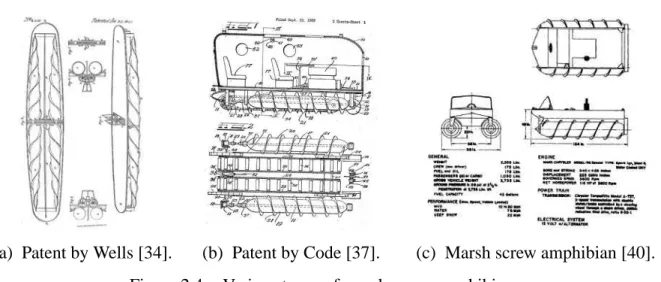
2.4(a) Patent by Wells [34] . . . 16
2.4(b) Patent by Code [37] . . . 16
2.4(c) Marsh screw amphibian [40] . . . 16
2.4 Various types of marsh screw amphibians . . . 16
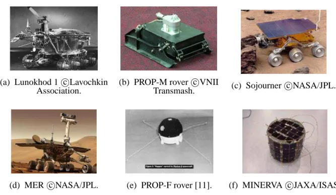
3.1(a) Lunokhod 1 c°Lavochkin Association . . . 21
3.1(b) PROP-M rover c°VNII Transmash . . . 21
3.1(c) Sojourner c°NASA/JPL . . . 21
List of Figures
3.1(d) MER c°NASA/JPL . . . 21
3.1(e) PROP-F rover [11] . . . 21
3.1(f) MINERVA c°JAXA/ISAS . . . 21
3.1 Space exploration rovers launched in past and current missions . . . 21
3.2(a) Indoor experimentation . . . 21
3.2(b) Computer simulation . . . 21
3.2 Trial-and-error approach for extricating the stuck Spirit rover c°NASA/JPL 21 3.3(a) Friction against ground . . . 22
3.3(b) External contact . . . 22
3.3(c) Additional thruster . . . 22
3.3 Method of propulsive force for locomotion on rigid ground . . . 22
3.4(a) 3D CAD drawing . . . 24
3.4(b) Prototype overview . . . 24
3.4 Schematic of Screw Drive Rover system . . . 24
3.5(a) Internal structure of main body and hinge legs . . . 25
3.5(b) Cross-section diagram of screw drive unit . . . 25
3.5 Mechanical structure of Screw Drive Rover . . . 25
3.6 Illustration of moving hinge legs (front view) . . . 26
3.7 Simplified dynamics model of Screw Drive Rover . . . 28
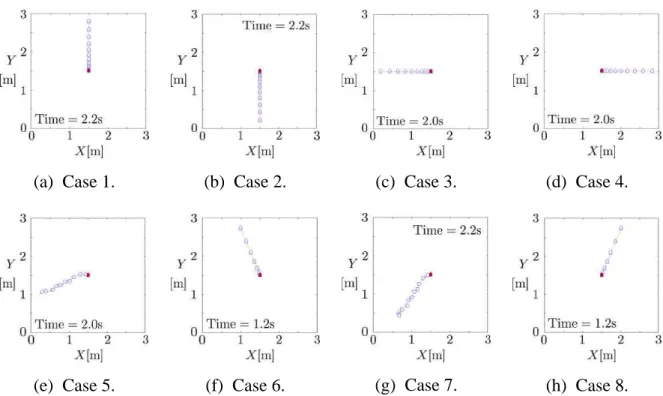
3.8(a) Case 1 . . . 29
3.8(b) Case 2 . . . 29
3.8(c) Case 3 . . . 29
3.8(d) Case 4 . . . 29
3.8(e) Case 5 . . . 29
3.8(f) Case 6 . . . 29
3.8(g) Case 7 . . . 29
3.8(h) Case 8 . . . 29
3.8 Simulation results: Dynamic trajectories of the Screw Drive Rover model 29 3.9(a) Frwith resistances . . . 30
3.9(b) k1with resistances . . . 30
3.9(c) ωrandωl with resistances . . . 30
3.9(d) 3D plots of accelerations with resistances . . . 30
3.9(e) 2D plots of accelerations with resistances . . . 30
List of Figures
3.9 Simulated distribution of parameters and generated accelerations with
η = 30 deg . . . 30
3.10(a) 3D plots atη= 15 deg . . . 31
3.10(b) 2D plots atη= 15 deg . . . 31
3.10(c) 3D plots atη= 45 deg . . . 31
3.10(d) 2D plots atη= 45 deg . . . 31
3.10(e) 3D plots atη= 75 deg . . . 31
3.10(f) 2D plots atη= 75 deg . . . 31
3.10 Simulated distribution of accelerations without frictional resistances: variousη . . . 31
3.11(a) 3D data at k2= 0.5 . . . 32
3.11(b) 2D data at k2= 0.5 . . . 32
3.11(c) 3D data at k2= 2 . . . 32
3.11(d) 2D data at k2= 2 . . . 32
3.11 Simulated distribution of accelerations without frictional resistances: η = 30 deg and various k2 . . . 32
3.12 Kinematics model of the screw unit . . . 34
3.13 Soil-screw interaction model . . . 35
3.14 Relationship betweenθs f and h/R0 . . . 35
3.15(a) Trajectories of screw flight and soil displacement . . . 37
3.15(b) Soil shearing ellipse . . . 37
3.15 Elliptic trajectory of soil shearing . . . 37
3.16(a) Illustration of effective shearing distance . . . 38
3.16(b) Parametric analysis of dsdepending onη . . . 38
3.16 Effective distance of soil shearing . . . 38
3.17 Motion resistance by bulldozing soil . . . 40
3.18 Simulation plots of FBxand hB . . . 40
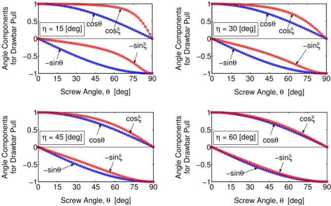
3.19 Angle components of stresses for drawbar pull on circular and elliptic surfaces along angles . . . 42
3.20(a) With varyingη, c3= 0.2 and c4= 0.03 . . . 44
3.20(b) With varying c3, c4= 0.03 andη = 16 deg . . . 44
3.20(c) With varying c4, c3= 0.2 andη = 16 deg . . . 44
3.20 Simulated drawbar pull and slip of the Screw Drive Rover model . . . . 44
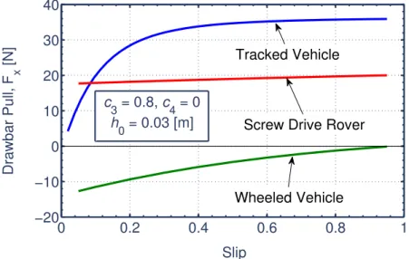
3.21 Comparative simulation result of Screw Drive Rover model with wheeled and tracked vehicle models . . . 45
List of Figures
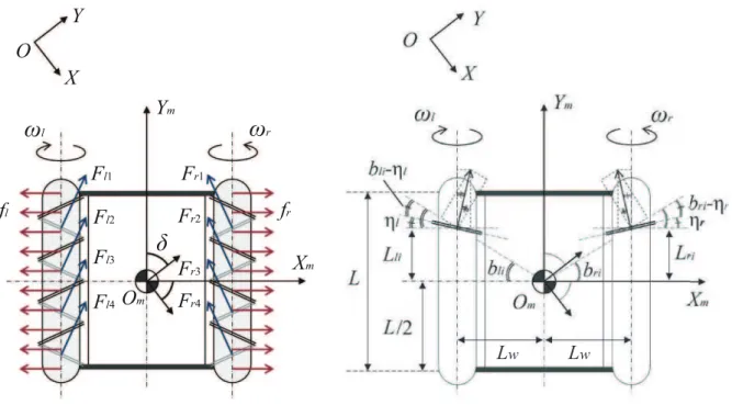
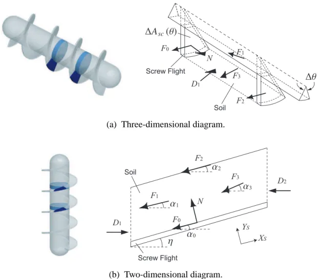
3.22(a) Three-dimensional diagram . . . 47
3.22(b) Two-dimensional diagram . . . 47
3.22 Interactive traveling model of the screw flight and the soil . . . 47
3.23(a) Simulated characteristics of drawbar pull and slip . . . 50
3.23(b) Comparative simulation . . . 50
3.23 Simulation results of drawbar pull based on synthetic model . . . 50
4.1 Schematic of laboratory tests. . . 52
4.2 Three-dimensional CAD model of screw unit apparatus . . . 52
4.3(a) Overview . . . 53
4.3(b) Screw unit on test sand . . . 53
4.3 Photograph of the experimental apparatus . . . 53
4.4 Grain size accumulation curve of quartz sand . . . 54
4.5 Coordinate of the screw unit . . . 54
4.6 Definition of slip angle . . . 54
4.7 Initial test condition . . . 55
4.8 Data example measured by sensors (load is 1.5 kilograms without trac- tive drag) . . . 56
4.9(a) Load: 1.5 kg . . . 57
4.9(b) Load: 2.0 kg . . . 57
4.9(c) Load: 2.5 kg . . . 57
4.9(d) Approximate lines . . . 57
4.9 Experimental drawbar pull: Effect of load (rotational velocity: 45 deg/s, slip angle: 0 deg) . . . 57
4.10(a) Rotational velocity: 45 deg/s . . . 58
4.10(b) Rotational velocity: 30 deg/s . . . 58
4.10(c) Approximate lines . . . 58
4.10 Experimental drawbar pull: Effect of rotational velocity (load: 2.5 kg, slip angle: 0 deg) . . . 58
4.11(a) Slip angle: +10 deg . . . 59
4.11(b) Slip angle: -10 deg . . . 59
4.11(c) Approximate lines . . . 59
4.11 Experimental drawbar pull: Effect of slip angle (load: 2.5 kg, rotational velocity: 60 deg/s) . . . 59
List of Figures
4.12(b) Normalized drawbar pull . . . 60
4.12(c) Ratio of cos(α+10)/ cos(α0+ 10) . . . 60
4.12(d) Ratio of cos(α−10+ 20)/ cos(α0+ 10) . . . 60
4.12 Experimental analysis on drawbar pull with slip: Effect of slip angle . . 60
4.13 Experimental results and simulations of drawbar pull: Effect of load . . 62
4.14 Experimental results and simulations of drawbar pull: Effect of rota- tional velocity . . . 62
4.15 Experimental results and simulations of drawbar pull: Effect of slip angle 62 4.16 Sandy terrain in laboratory tests . . . 63
4.17 Experimental characteristics of laboratory tests . . . 64
4.18 Various rut formations by the prototyped rover on sand . . . 65
4.19(a) Forward movement by outward screw revolution . . . 66
4.19(b) Backward movement by inward screw revolution . . . 66
4.19(c) Right sideways steering . . . 66
4.19(d) Left sideways steering . . . 66
4.19(e) Right-front steering . . . 66
4.19(f) Right-rear steering . . . 66
4.19(g) Left-front steering . . . 66
4.19(h) Left-rear steering. . . 66
4.19 Diverse mobility performance demonstrated by Screw Drive Rover pro- totype on soil surface . . . 66
4.20(a) ωr: large ccw,ωl: small ccw . . . 67
4.20(b)ωr: large ccw,ωl: large ccw . . . 67
4.20(c) ωr: small ccw,ωl: large ccw . . . 67
4.20 Left sideways steering trajectories demonstrated by different inputs . . . 67
4.21(a) Simulation model . . . 67
4.21(b) Simulation window . . . 67
4.21 Analysis model of maneuvering trajectories . . . 67
4.22(a) Starting to move (t = 0.0 s) . . . 68
4.22(b) Pushing a rock (t= 2.6 s) . . . 68
4.22(c) Climbing a rock (t= 4.1 s) . . . 68
4.22(d) Achievement (t= 8.4 s) . . . 68
4.22 Video images of climbing a rock by the Screw Drive Rover prototype . . 68
5.1 Apollo project’s seismometer deployed on the Moon c°NASA . . . 72
List of Figures
5.2(a) Schematic of LUNAR-A penetrator . . . 72
5.2(b) Long-term seismometer . . . 72
5.2 LUNAR-A penetrator system c°JAXA/ISAS . . . 72
5.3(a) PLUTO Mole [161] . . . 76
5.3(b) IDDS [164]. . . 76
5.3(c) MMUM [170] . . . 76
5.3(d) SSDS/RPDS [167] . . . 76
5.3(e) MOGURA2001 [160] . . . 76
5.3(f) Mole-type Robot [163] . . . 76
5.3(g) Regolith Drilling Robot [180] . . . 76
5.3(h) Earthworm-type Robot [179] . . . 76
5.3 Conventional subsurface explorers . . . 76
5.4 Schematic of robotic subsurface exploration mission on the Moon . . . . 79
5.5(a) Boring drill model . . . 80
5.5(b) Subsurface explorer model . . . 80
5.5 Models of lateral soil frictional . . . 80
5.6(a) Case of boring drill . . . 81
5.6(b) Case of subsurface explorer . . . 81
5.6 Propulsive depth limit estimation . . . 81
5.7 Simulation result of soil pressure propagation range . . . 82
5.8(a) CC= 0.050 (weakly-compressible) . . . 84
5.8(b) CC= 0.075 (middle-compressible) . . . 84
5.8(c) CC= 0.10 (highly-compressible) . . . 84
5.8 Estimated results of compressing soil to make a space . . . 84
5.9 Robotic mechanisms for the subsurface locomotion strategies . . . 85
5.10(a) Geometric model. . . 86
5.10(b) Prototype . . . 86
5.10(c) Dynamic principle . . . 86
5.10 Single conical screw unit: SSD . . . 86
5.11 Basic drilling characteristics of SSD . . . 86
5.12(a) Three-dimensional diagram . . . 89
5.12(b) Two-dimensional diagram . . . 89
5.12 Interactive drilling model of the screw flight and the soil. . . 89
List of Figures
5.15(a) Relation between MT and h . . . 96
5.15(b) Relation between MT andη . . . 96
5.15(c) Relation between MT,φ and C . . . 96
5.15(d) Relation between MT,(1 +ν)/E and∆ . . . 96
5.15 Simulation results of parametric analysis . . . 96
5.16 Experimental overview. . . 97
5.17 Grain size accumulation curves of test soils . . . 97
5.18(a) Quartz sand . . . 99
5.18(b) Fly ash . . . 99
5.18(c) Lunarant . . . 99
5.18 Comparison of simulation result with experimental data . . . 99
6.1(a) Geometric model. . . 102
6.1(b) Prototype . . . 102
6.1(c) Prospective functions of the screws . . . 102
6.1 Contra-rotor screw unit: CSD . . . 102
6.2(a) Overview . . . 105
6.2(b) System configuration. . . 105
6.2 Experimental environment . . . 105
6.3(a) Stronger reaction mode: Kω ≃ 18.8 . . . 106
6.3(b) Non-reaction mode: Kω ≃ 62.5 . . . 106
6.3 Experimental view of the reaction modes targeting quartz sand . . . 106
6.4(a) Targeting quartz sand . . . 107
6.4(b) Targeting Lunarant under the body is fixed. . . 107
6.4 Experimental results of CSD: Relation between PR and Kω . . . 107
6.5(a) Targeting quartz sand . . . 107
6.5(b) Targeting Lunarant under the body is fixed. . . 107
6.5 Experimental results of CSD: Relation between SE and Kω . . . 107
6.6(a) Targeting quartz sand . . . 107
6.6(b) Targeting Lunarant under the body is fixed. . . 107
6.6 Experimental results of CSD: Relation between PR, f1and f2 . . . 107
6.7(a) f = 9.2 rpm . . . 109
6.7(b) f = 11.5 rpm . . . 109
6.7(c) f = 13.8 rpm . . . 109
6.7 SSD’s driving torques with the various screw’s rotational speed . . . 109
List of Figures
6.8(a) f1= 46.7 rpm (Kω = 3.67) . . . 109
6.8(b) f1= 38.9 rpm (Kω = 3.06) . . . 109
6.8(c) f1= 31.1 rpm (Kω = 2.45) . . . 109
6.8(d) f1= 23.4 rpm (Kω = 1.84) . . . 109
6.8 CSD’s driving torques with the various f1under f2= 12.7 rpm . . . 109
6.9 Comparative data of the driving torques of SSD and CSD with maxi- mum inputs . . . 110
6.10 Experimental analysis results of CSD at 65mm depth: Relation of MSE and Kω (ηM= 0.50, W = 5.925 N and f2= 12.7 rpm) . . . 110
6.11(a) 3D CAD model . . . 111
6.11(b) Schematic of internal structure . . . 111
6.11 Mechanical design of screw subsurface explorer . . . 111
6.12 Prototype of robotic screw explorer . . . 112
6.13(a) Before driving . . . 113
6.13(b) During experiment . . . 113
6.13(c) After experiment . . . 113
6.13 Photographs of drilling experiment by subsurface screw explorer . . . . 113
6.14 Experimental result with simulation plots . . . 113
A.1 Kinematic control model of the Screw Drive Rover . . . 122
A.2 Simulation result of motion trajectory with moving direction control αd=π/4 rad . . . 124
B.1 The Standard of Ur “War” in Sumerian civilization [112] . . . 125
B.2 Traditional simplified soil-wheel interaction model . . . 128
B.3 Relationship betweenθw f and hw/rw . . . 128
B.4 Schematic of single wheel test system . . . 130
B.5 Stress distributions alongθw:—σ, —τ . . . 131
B.6(a) Effect of swwith rw/K = 1 . . . 132
B.6(b) Effect of rw/K with sw= 0.5 . . . 132
B.6 Shear function alongθwwith constant hw/rw . . . 132
B.7 Integrated forces vs. slip with constant hw/rw . . . 133
B.8(a) Simulated drawbar pull . . . 133
B.8(b) Simulated vertical force . . . 133
List of Figures
B.10 Drawbar pull vs. slip with various c4. . . 134
B.11 Description of slip-traction characteristics . . . 134
B.12(a) Effect of K . . . 134
B.12(b) Effect of rw/K . . . 134
B.12 Minimal hw/rwsatisfying DPw≤ 0 with various rwtargeting dry sand . . 134
B.13(a) Effect of K . . . 135
B.13(b) Effect ofφ . . . 135
B.13 Minimal hw/rwsatisfying DPw≤ 0 with various rwtargeting lunar soil . 135 B.14 Tendency resulted by single wheel test . . . 136
C.1(a) Illustration of vehicle model . . . 139
C.1(b) Track-soil interaction model . . . 139
C.1 Rigid tracked vehicle model . . . 139
D.1(a) Simplified penetrator model . . . 142
D.1(b) Simulation result . . . 142
D.1 Cone penetration by Sandia equation . . . 142
List of Figures
List of Tables
3.1 Achievements of unmanned exploration rovers . . . 20
3.2 Performance comparison of single locomotive gears on soil . . . 22
3.3 Simulation conditions for motion trajectories . . . 29
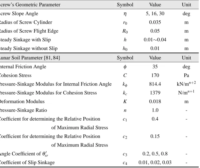
3.4 Simulation parameters for prediction of drawbar pull . . . 43
4.1 Simulation parameters for prediction of experimental drawbar pull . . . 61
4.2 Resulting classification of maneuvering trajectories . . . 67
4.3 Compatibility analysis of ideal force models resulted from empirical maneuvers . . . 68
5.1 Past drilling missions on the Moon . . . 73
5.2 Comparison of drilling techniques in lunar and planetary explorations . . 74
5.3 Mechanism classification of the conventional subsurface explorers . . . 77
5.4 Practical achievements of the conventional subsurface explorers . . . 77
5.5 Parameters to estimate depth limit . . . 81
5.6 Physical properties of test soils . . . 98
6.1 Specifications of the screw prototypes . . . 105
6.2 Fundamental specifications of the prototype . . . 112
6.3 Simulation case study for design guideline . . . 114
B.1 Nominal parameters of dry sand in simulation analyses . . . 130
B.2 Nominal parameters of lunar soil in simulation analyses . . . 135
D.1 Simulation parameters of penetrator model . . . 142
List of Tables
Chapter 1. Introduction
1.1 Background
Mankind has been attracted to the universe since early times. “The Earth is the cradle of the mind, but we cannot live forever in a cradle.”, the famous line written by K. E. Tsiolkovsky in 1911, a rocket scientist and a pioneer of astronautics in the former Soviet Union. As summa- rized by his quote, space is now looked on as the new frontier for mankind’s activities. Interest in space has also come from an academic viewpoint, for example, from astronomy or celes- tial mechanics. Contributions of space development generally cover a lot of disciplines (for instance, space science, life science, material science and engineering). As the first world’s suc- cessful space project, in 1957 the Soviet Union launched an artificial satellite into orbit around the Earth. The satellite was named Sputnik 1 (Figure 1.1), and its success began the Moon race between the Soviet Union and the USA [5]. At that time, the Moon race included a prominent political dimension because of the so-called “Cold War”. But, ironically, the race made a sizable contribution to the immediate development of space technology through bountiful budgets. As a result, the USA achieved the first manned landing on the Moon by the Apollo 11 project in 1969. Figure 1.2 shows an astronaut’s footprint on the Moon from this project. After the Moon race era, space development has been shifting from extensive manned missions to relatively small unmanned explorations aiming at scientific research in space science. Within this context, more
Figure 1.1 : The first world’s artificial satellite “Sputnik 1” c°USSR.
1.1 Background
Figure 1.2 : Footprint on the lunar surface c°NASA.
and more countries are currently entering into space development. Furthermore, robotization and automation technology is becoming increasingly central to the space explorations. Space robotics is also developing rapidly with recent progress of science technology. Generally, ap- plications of robotic technologies enable the conduction of challenging tasks in difficult terrains such as volcanoes, rescue sites or extraterrestrial surfaces. A growing number of the robotic technologies will advance future space missions as space robotics leads to accomplishments of precise works with lower cost and risk in the extraterrestrial surfaces. To realize the challenging tasks, however, epoch-making technologies of space robotics are now required.
Originally, the word of “robot” was coined by famous Czech writer K. ˇCapek in his science fiction play R.U.R. (Rossum’s Universal Robots) which was premiered in 1921. Its etymology is the word “robota”, meaning labour in Czech. In this play, artificial people were called “robots”, and at the beginning, the word was closer to androids or bioroids, unlike the modern idea of robots. Likewise, in 1941, the term “robotics” was first used in science fiction short story Liar! written by prolific American writer I. Asimov. The word “robotics” was created as a cross- sectoral term including all the knowledge and technologies with respect to robots. The idea of the robot coined just 90 years ago has currently constituted the bedrock of space development. Here, as expectations for the lunar and planetary exploration by the robotic technology, an im- portance of surface locomotion technique and sampling materials was noted by Yoshida [119]. In particular, mobile rovers have attracted attention in the actualization of robotic exploration. For upcoming rover missions, the development of robust locomotion and investigation systems
1.2 Motivation
1.2 Motivation
1.2.1 Requirements for Space Robotics
In general, the requirements need to be considered for all components making up the space robotic technologies as follows:
• Small-sized and lightweight system as sending materials into space costs a large amount of money and there is a limit to the transportable volume/mass by rockets.
• Structural simplicity to ensure mechanical and electrical reliability.
• Redundant or robust system to deal with unforeseen situations.
• Thrifty power consumption for reduced availability of electrical power in space.
• Applicability or tolerability to harsh space environments: ultra-high vacuum, thermal con- dition, gravitational field and space radiation.
Unmanned exploration rovers on the lunar and planetary surfaces cannot rely on human sup- port. Therefore, the rovers must recover from or avoid critical situations by themselves. Also, structural or mechanical reliability of the rovers becomes critical. With respect to future rover missions, an attainment of unmanned surface and subsurface locomotion (i.e., traveling and drilling) in soft terrain covered with fine soils is a key technique. This research focuses on an Archimedean screw mechanism as a prospective structure achieving both the surface and the subsurface locomotion.
1.2.2 Applicability of Archimedean Screw Mechanism
An Archimedean screw spiral is an interesting and useful structure in engineering. Humans have been intensely interested in such a spiral structure since ancient times [46, 57, 65]. The Archimedean screw is a device for moving solid or liquid materials by means of a rotating he- lical flighting. As can be expected from the name, it is said that its invention is credited to the Greek mathematician Archimedes of Syracuse in the 3rd century BC [65]. Originally, the Archimedean screw mechanism was utilized as a screw-pump [53]. Figure 1.3(a) shows profile of a screw pump. The Archimedean screw pump is a mechanical device for transferring water from a low-lying body of water into irrigation ditches. The screw pump is typically composed of a screw flight and a hollow pipe, and the screw flight is installed inside the hollow pipe. Turning the screw flight and/or the pipe allows one to scoop up a volume of water. Likewise,
1.3 Purpose and Approach
the Archimedean screw mechanism has been used for conveying not only liquid but granular materials [49, 56, 58]. As for the screw conveyors, some has studied their theoretical analysis such as a transportation efficiency. However, the screw is fixed and just motions of transported materials is considered.
Traditionally, a screwed drill has been also utilized in field excavation, the so-called earth auger [15, 16, 19]. The earth auger is a mechanical tool for removing soil, clay and shavings of rocks using working fluid by a rotating helical flight. Figure 1.3(b) shows an earth auger ma- chine. Like the liquid in a screw-pump, excavated materials are transported along its rotational axis. While the earth auger excavation has been extensively-employed, its interactive mechanics with surrounding soil remains to be studied. Furthermore, there has been a screwed pile, which is the almost same structure with the earth auger. The screw pile has been applied with the purpose of structural stability against overturning moments, uplift forces, axial compression and lateral forces [24]. Figure 1.3(c) shows the screw piles. The screw piling foundation is becoming a typical technique in everyday construction sites because of its simplicity. The widespread use of the screw pile is attributed to its efficient pile installation rate. The screw pile has a helical flight twisting around a shaft, which is analogous to the screw pump. So far, most theoretical discussions of the screwed pile have been focused on its bearing capability. In this case, a soil- screw interaction is a moot point.
Additionally, since the 19th century, the Archimedean screw has been applied to land and amphibious vehicles [34–37]. Figure 1.3(d) shows the marsh screw amphibian developed by the US army. It has been confirmed that the vehicles provide high trafficability on difficult surfaces consisting of snow, ice, mud, marsh or sand. Specifically the surface locomotion in soil by the screws becomes more complicated than subsurface locomotion due to anisotropy of contact constraint with its environments. Discussions on theoretical soil-screw interaction re- mains controversial, and also the vehicle’s trafficability and maneuverability have not been well understood.
1.3 Purpose and Approach
In accordance with the above considerations, although the Archimedean screw mechanism has been variously-used to machine technology, the soil-screw interaction remains to be elucidated. At present, academic studies on the undissolved interaction are extremely-limited in the world. Elucidation of the interaction is expected to make a contribution to practical enhancements, such
1.3 Purpose and Approach
(a) Archimedean screw pump [50]. (b) Earth auger machine c°Hokuriku Eletec Co., Ltd..
(c) Screw piles c°Apollo Piling Systems. (d) Marsh Screw Amphibian [45]. Figure 1.3 : Practical applications of the Archimedean screw mechanism.
to provide the findings of an interactive mechanics between soil and the screw and to develop a new soil-screw interaction model. This interaction is discussed through considerations of:
• Surface Locomotion (traveling on soft terrain) by the Archimedean screws
• Subsurface Locomotion (drilling into soft terrain) by the Archimedean screws
For subsurface locomotion, the screw’s contact constraint normal to a propulsive direction is isotropically-distributed in compressible soils. Meanwhile, for the surface locomotion, the screw is anisotropically-constrained by the soils in three-dimensional space. Therefore, the surface locomotion becomes more complicated for mobile exploration robots. An integrative discussion of both the surface and the subsurface locomotion will exhibit key ideas on the inter- active mechanics. The discussion takes into account the screw’s different locomotive directions to a gravitational direction.
1.4 Research Contributions
1.4 Research Contributions
This dissertation focuses on understanding the soil-screw interaction of surface and subsurface locomotion in soft terrain. Compared with conventional screw applications, the characterization of this research is described as shown in Figure 1.4 The main contributions of this research are:
• New initiative of the Archimedean screw mechanism
With respect to applications to the surface and the subsurface locomotion on the soft terrain, a potential capability of the Archimedean screw mechanism is systematically- studied. Also, advantages of the screw mechanism are qualitatively summarized by com- parison with other mechanisms.
• Integrative discussion of the soil-screw interaction
This dissertation introduces a synthetic idea of the the soil-screw interaction from the viewpoint of the surface and the subsurface locomotion. The interaction is discussed by both experimental and theoretical approaches for each locomotion technique.
• Formulation of the soil-screw interaction
Mathematical formulation of the interaction is derived, and it contributes to a better un- derstanding of the unknown interactive mechanics. The formulation also leads to optimal design and control of the screw. As for space applications, its reliability can be prelimi- narily evaluated by using the formulated model.
• Proposal of an effective screw drilling mechanism
To achieve an efficient screw drilling, this dissertation proposes a new screw mechanism. Its valid conditions are experimentally evaluated.
1.5 Outline
This dissertation is organized into 7 chapters as described in Figure 1.5. The contents of each chapter are briefly summarized as follows:
Chapter 1 introduces the background and the motivation of this research, and then describes the purpose and the approach. Also, the main contributions of this dissertation are mentioned.
Chapter 2 presents mathematical definitions of fundamental screw mechanisms. Moreover, as the historical background, related works of the screw applications to the surface and the sub-
1.5 Outline
are articulated.
Chapter 3 describes the soil-screw interaction modeling for the surface locomotion by the Archimedean screw mechanism. Ideas on soil-screw interaction models are discussed based on skin friction and terramechanics (soil compaction and shear). In accordance with these modeling concepts, this chapter introduces a novel model by combining skin friction and terramechanics. Unlike conventional locomotion models, the synthetic model can simulate both contact friction and soil behavior.
Chapter 4 presents the surface locomotion system by using the Archimedean screw mech- anism. This chapter also proposes the Screw Dive Rover system driven by the Archimedean screw units as a new rover for traveling on the soft terrain. Prior to detailed discussions, advan- tages of locomotion by the screw unit to conventional locomotion gears (a wheel and a track) are mentioned. Then, in this chapter experimental trafficability and maneuverability of the Screw Drive Rover system are analyzed by laboratory tests. In addition, propulsive forces’ directions to be reacted are examined based on the maneuverability and the trafficability. The resulted characteristics are discussed by comparison to simulation results in Chapter 3.
Chapter 5 addresses the subsurface locomotion by the Archimedean screw mechanism. A key strategy of how to move underground is first described qualitatively, and possible mechanisms achieving the strategy are enumerated. On the basis of this consideration, it is indicated that the Archimedean screw is one of the most useful mechanisms for subsurface drilling. Additionally, a novel soil-screw interaction model of the subsurface locomotion is developed. Parametric sim- ulation analyses are conducted to examine the characteristics of the proposed model. The model validation is also evaluated by experimentations and numerical simulations.
Chapter 6 deals with a new effective screw drilling mechanism. To accomplish efficient drilling on the Moon, a contra-rotor screw drilling mechanism is proposed. The mechanical objective of this new mechanism is agitating compacted subsoils and canceling motor reaction torques by an unique structure. The adequacy of this mechanism is evaluated by using energetic indexes through drilling experiments. Furthermore, this chapter proposes a new subsurface ex- plorer by applying the Archimedean screw mechanism, which can burrow into the soil by itself. Its experimental validity is examined with the developed model in Chapter 5.
Chapter 7 summarizes the contributions of this dissertation. Moreover, several future works are described as additional challenges.
1.5Outline
Archimedean Screw Mechanism
Subsurace Locomotion (Drilling) Surace Locomotion (Traveling) Contact Constraint:
isotropically-governed by compressible soil
Contact Constraint:
anisotropically-governed by compressible soil
Conventional Research Earth Auger
- widespread use in construction - investigation of geometic effects Screwed Pile
- discussion of bearing capability - investigation of geometic effects - limited mathematical modeling
Conventional Research
Challenges - understanding of soil-screw interaction mechansim - mathematical modeling of soil-screw interaction - mechanical improvement for effective screw mechanism
Challenges
- understanding of soil-screw interaction mechansim - mathematical modeling of soil-screw interaction - systematic investigations of mobilty performance Conveyor
- water - granular materials
Propeller - vessel - underwater robot Other
Applications
- ... - ... - ... - ... - ... - ... - ... - ... - ... Potential Application
This Dissertation Contribution
Marsh Screw Amphibian - limited empirical elaborations - investigation of a few screw geometric effects
- many patents (e.g. vehicle, hobby) - limited mathematical modeling
-8-
1.5 Outline
Chapter 1 Introduction
1. Background
2. Motivation and Challenge 3. Objective
4. Contributions
Chapter 5 Modeling and Analysis
1. [Statement] Technological background 2. [Proposal] Locomotion strategy 3. [Proposal] Soil-screw interaction model 4. [Validation] Experiments and simulations
Subsurface Locomotion Surface Locomotion
Chapter 6 Proposal of Effective Screw Drilling and Total Systemg
1. [Propose] Contra-rotor screw drill 2. [Validation] Experimenatal analyses 3. [Proposal] Subsurface screw explorer 4. [Validation] Experimens and simulations
Outline of Thesis
Theme: Understanding of Soil-Screw Interaction
Traveling on Soft Terrain Driling into Soft Terrain
Chapter 4 Experimental Analyses
1. [Statement] Technological background 2. [Proposal] Screw Drive Rover system 3. [Analysis] Empirical maneuverability 4. [Analysis] Empirical trafficabiliy 5. [Discussion] Compatible force model
Chapter 3 Modeling and Analysis
1. [Proposal] Soil-screw interaction model - modeling based on skin friction - modeling based on terramechanics 2. [Validation] Simulation analyses
Chapter 7 Conclusions
1. Summarizing remarks 2. Future works
Chapter 2 Archimedean Screw
1. Overview Archimedean Screw 2. Related Works
3. Mathematical Definitions of Fundamental Screw Geometry
Figure 1.5 : Configured outline of this dissertation.
1.5 Outline
Chapter 2. Archimedean Screw
Mechanism
An Archimedean screw mechanism is an attractive structure and has been used in various applications as described in Chapter 1. This dissertation especially focuses on its application to surface and subsurface locomotion in soft terrain (i.e., traveling on surface and drilling into subsurface). In the meantime, studies on the screw has been quite limited and it includes a lot of missing parts academically. To apply it to deformable terrain such as soil, theoretical and systematic discussions are required. First of all, this chapter derives mathematical definitions of fundamental screw mechanisms as preliminary matters for the subsequent chapters.
2.1 Geometric Modeling of Screw Mechanism
In this dissertation, two types of the Archimedean screw mechanisms are considered: a loga- rithmic and a cylindrical helix. Hereη denotes the constant inclination angle of screw flight at the center position P on the screw flights. As common terms, the screw length is L, the maximum inner radius of the screws is r0and the maximum screw radius is R0. In addition, logarithmic and cylindrical screw models can be mathematically expressed as a function of the winding screw angleθ against a cone and a cylinder in Figure 2.1. Also, the screw thickness is neglected. As coordinates, l axis is set to be the central axis of the explorer, and r is defined as the distance from l axis as shown in Figure 2.1, respectively. Furthermore, l denotes the height from the apex of the screw andθ is set to be zero at the highest position of the screws. At a winding angle θ, rc, rs, and rscare defined as the inner screw radius, the outer screw radius, and the distance from l axis to P, respectively. The mathematic models of the helices can be defined as follows.
R=
RLexp(aθ) : Logarithmic Helix RC : Cylindrical Helix
(2.1)
2.1 Geometric Modeling of Screw Mechanism
and also,
R = hrc(θ) rs(θ) rsc(θ) l (θ) iT
RL = hr0 R0 R L iT
RC =
·
r0 R0 R L−pθ 2π
¸T
R = r0+ R0 2
(2.2)
where p is the screw pitch and the function parameter a is negative (i.e., a< 0). Thus P can be represented as a function of rsc and l in r-l coordinates. Figure 2.2 shows examples of a cylindrical and a logarithmic helix based on Eq. (2.1).
2.1.1 Screw Slope Parameter
This section introduces a method to derive geometric screw slope parameter a. The slope angleηat the point P on the screw flight is set to be a constant value. According to this condition, the functional parameter a can be described as a correlation function ofη by differentiating P. Given a constantη, a is derived as follows.
a=p −R tanη
(L + R tanη)(L − R tanη) (2.3)
(a) Logarithmic helix. (b) Cylindrical helix. Figure 2.1 : Geometric models of screw helices.
2.1 Geometric Modeling of Screw Mechanism
−30 −15
0 15
30
−30
−15 0 15 300 10 20 30 40 50
−30 −15 0 15 30
−30
−15 0 15 30
θ r = R
P
η = 10 [deg]
(a) Cylindrical helix.
−30 −15
0 15
30
−30
−15 0 15 300 10 20 30 40 50
−30 −15 0 15 30
−30
−15 0 15 30
θ
η = 10 [deg] P
r = R
(b) Logarithmic helix.
Figure 2.2 : Mathematical drawing of screw helices.
2.1.2 Screw Pitch
While the screw pitch p of a cylindrical helix is constant, but the effective p of the logarith- mic helix becomes a variable value at θ. The helical screw pinches correspond to the vertical intervals between the screw flights. The pitch p of the cylindrical and logarithmic helices can thus be defined as a differential of l betweenθ andθ− 2π as follows.
· Cylindrical Helix:
p=
θR tanη : 0≤θ ≤ 2π
2πR tanη :θ > 2π (2.4)
· Logarithmic Helix:
p=
L[1 − exp(aθ)] : 0≤θ ≤ 2π
L[exp(−2aπ) − 1] exp(aθ) :θ > 2π (2.5) For the Archimedean screw models, the pitches are constrained by the screw length L at the initial pointθ = 0.
2.2 Related Works
2.1.3 Screw Surface Area
An upper surface area of the screw flight is principal geometric information for discussing the screw dynamics since it denotes an interacting area between the screw surface and the soil. The upper surface area of the screw flight enclosed by an angleθ toθ+∆θ is defined as∆Asc(θ). The surface area is assumed to be the difference between surface areas approximated by trian- gles. Therefore,∆Asc(θ) can be calculated as follows.
· Cylindrical Helix:
∆Asc(θ) ≈R
2 0− r20
2 ·∆θ (2.6)
· Logarithmic Helix:
∆Asc(θ) ≈ R
20− r02
2 exp(2aθ) ·∆θ (2.7)
2.1.4 Slip
The intrusion or the locomotion speed in a longitudinal direction of the screws and the screw rotational speed of the screw are defined as v and f . With these parameters, the slip s [19, 43], which denotes the intrusion depth or the traveling distance for one screw rotation as to the screw pitch, can be defined as follows.
s= p f− v
p f ⇐⇒ sp = p − v
f (2.8)
2.2 Related Works
2.2.1 Historical Background of Screw Vehicles
So far, the Archimedean screw mechanism has also been applied to land vehicles and amphib- ians since around the 19th century, and there have been several patents in regard to such screw vehicles [34–45, 64]. Figure 2.4 shows some of past screw vehicles. Generally, the vehicles provide high trafficability in a difficult surface consisting of snow, ice, mud, marsh or sand. The vehicles are particularly expected to be robust to slipping and getting stuck in soft soil since the mechanism can forge ahead even if it is buried in the soil. Together, their inclined screw
2.2 Related Works
0 10 20 30 40 50 60
−1
−0.5 0
−0.25
−0.75
Screw Slope Angle, η [deg]
Helical Parameter, a
R = 0.02 [m] L = 0.05 [m]
(a) Relationship between a andη.
0 20 40 60
0 1 2 3 4 5x 10
−4
Screw Angle, θ [rad]
∆A sc/∆θ [m2 /rad] R0 = 0.025 [m]
r0 = 0.015 [m] a = −0.070707
(b) Relationship between∆Asc/∆θ andη.
0 20 40 60
0 0.005 0.01 0.015 0.02
Screw Angle, θ [rad]
Screw Pitch, p [m]
2π
L = 0.05 [m] a = −0.070707
(c) Relationship between p andθ.
Figure 2.3 : Functional behaviors of logarithmic screw geometry.
vehicle have been extremely limited [38, 41, 43, 64]. Consequently, an actual soil-screw inter- action remains to be elucidated from academic viewpoint. In such background of the vehicles, theoretical discussions of the screw vehicle have been conducted by Cole [38]. This work has attempted to analytically model and evaluate the vehicle’s traction performance on sand, but its model was developed based on just skin friction and ignored both slippage and soil shear phe- nomena. Therefore, the model is inadequate to be applied. On the other hand, Dugoff et al. [43] especially examined the characteristics between translatory traction and a slip of a single screw
2.2 Related Works
(a) Patent by Wells [34]. (b) Patent by Code [37]. (c) Marsh screw amphibian [40]. Figure 2.4 : Various types of marsh screw amphibians.
rotor by model tests. Their contributions suggested important remarks, which reported the effect of screw geometry, load and velocity on the characteristics. But its applicable scope would be confined to straight movement, and also researches on the soil-screw interaction are lacking. Consequently, the vehicles’ synthetic trafficability on the soil is less well understood. For this reason, a new challenge of comprehending the soil-screw interaction comes for a practical ap- plication of the screw.
Likewise, there have been several robots using a spiral mechanism, for instance, an in vivo robot for laparoscopy [54, 55], a robotic endoscope [60, 62], a rotational rheometer [47] or a swimming micro-machine [48, 51, 52]. These devices move by contact with viscoelastic bi- ological tissue or incompressible viscous fluid. Although these are equipped with the spiral mechanisms analogous to the Archimedean screw for locomotion, their targeted environments are quite different from soil. Further, mobile devices using a helical pipe/coil have been also developed [61, 63]. Their targets are outdoor soft surfaces [63] and wetlands [63], respectively. The device proposed in [63] is a patent, and thus its theoretical locomotion principle has not been considered. Understandably, their interactive models essentially differ from the the soil-screw interaction as well. Hence, individualistic modeling is practically required for each application. This dissertation focuses on the derivation of the novel soil-screw interaction model for sur- face locomotion. In particular, a novel mobile rover system, which is driven the Archimedean screw units, is proposed for discussing the interaction. To understand its fundamental mobility performance, modeling and analysis of the interaction are first conducted. Next, this dissertation investigates trafficability of the single screw unit and maneuverability of the rover. The traffica- bility and the maneuverability are examined through laboratory tests. These empirical mobility
2.2 Related Works
2.2.2 Historical Background of Screw Drilling
The screw drilling devices basically consist of a single unit with a cylinder/cone and a continu- ous helical screw flighting. Until now, they has been used as ground applications to construction field such as an earth-auger (e.g. [15, 16, 19]) and a screw pile (e.g. [24]) as described in Chapter 1. Initially, a auger drilling tool was used as a grain auger agriculture to move grain from trucks and grain carts into grain storage bins. It is said the modern grain auger was first prototyped by Peter Pakosh in 1945. On the other hand, the original screw pile was invented by Irish engineer Alexander Mitchell in 1833 [24]. Although its structural design was simple, the screw pile was utilized as effective means of construction for lighthouses, beacons, moorings and other struc- tures on muddy banks or shifting sands.
In general, these screw devices have the following important capabilities for a subsurface drilling technique:
• Backward fore-soil removal and transportation (achievement of making a space)
• Genesis of assisting force for intrusion by transporting fore-soil
• Dust prevention mechanism
The Archimedean screw mechanism is one of the most prospective drilling tools. Basically, a machined thread is superior in terms of intrusion with cutting materials. However it is not great at generating propulsive force by screw rotations because of the thread profile. Therefore, screw flights composed of flat and helical blades have been adopted as described in the subsequent subsections. Such screw mechanism is particularly expected to be suitable for drilling into com- pacted soil layer.
Meanwhile, many theoretical parts of the screw drilling remain to be elaborated. So far, there have some theoretical approaches [18, 19, 23, 30]. Hata et al. [18, 19] and Slatter et al. [23] have discussed the soil-screw interaction of the screw drilling. However, their models involve many theoretical insufficiencies as to definitions of forces, and the practical applicability of the models are not clear. Additionally, Fukada et al. [30] have studied the soil discharging model. In the modeling process, the soil-screw interaction has been also represented as prelim- inary definitions. But the model also includes lacking parts of acting forces and an unknown force remains to be defined. As for the screw piles, some have also addressed theoretical dis- cussions [21, 22, 28, 29, 31, 32]. The theoretical analyses on the screw piles have particularly focused on an evaluation of their bearing capability. Accordingly, most of them have not mod- eled the soil-screw interaction. For realizing an effective and autonomous screw mechanism, its
2.3 Summary
modeling is a new challenge. Unlike most ground applications, unmanned exploration robots do not allow for human intervention. Therefore, mechanical reliability and high efficiency based on theoretical analyses should be proved for practical applications of the screw.
This dissertation aims at the derivation of the novel soil-screw interaction model for subsur- face drilling. The model is introduced based on soil mechanics with screw behavior. Unlike the surface locomotion model, influences in a direction of gravitational force are particularly involved. Of particular note is that the fundamentals of the model is analogous to the model for surface locomotion.
2.3 Summary
Understanding an interactive mechanics between a mechanical tool and environment is quite important for unmanned robotic explorations. Not only the screw mechanisms, but all the tools in the soft terrain need mathematical modeling in order to efficiently use them. In this chap- ter, prior to detailed discussions of the soil-screw interaction, some of geometric and kinematic definitions of the helical screws were introduced. By considering them, the interaction models will be provided as functions of the screw geometry. Furthermore, the historical backgrounds with respect to screw drilling and screw vehicles were introduced from the viewpoint of their theoretical frameworks. According to these remarks, the necessity for developing a new interac- tion modeling was pointed out. This chapter reaffirmed that the development of the soil-screw interaction model is the key challenge to be addressed.
Chapter 3. Modeling of Screw Surface
Locomotion
3.1 Challenge Statement for Robotic Surface Locomotion
Robotic exploration by mobile rovers has received attention worldwide for the achievement of progressive space missions. In the history of space exploration, Lunokhod 1 and 2 built by the Soviet Union were the first unmanned rovers [113, 115, 116]. These huge rovers moved onto the lunar surface in 1970 and 1973, and were teleoperated from Earth. Recently, the So- journer rover [117] and the Mars Exploration Rovers (MERs) [123] operated by NASA have performed impressive exploration activities on Mars. They employ six wheels for traveling over the Martian surface, and the MERs have especially acquired scientific findings for more than 6 years [124, 126, 138]. In their locomotion mechanism, these three rovers have the rocker-bogie suspension mechanism to traverse rocky terrains [125]. Until now, there have been some lunar and planetary rovers adopted in actual missions as shown in Table 3.1 and Figure 3.1. Most of them employ wheels as their locomotion system because of reliability, simplicity and efficiency. Although the wheels were not selected to especially move on an asteroid’s surface under micro- gravity (e.g., PROP-F [116, 118] or MINERVA [121]), the wheels have contributed most to the exploration rovers (see Table 3.1). Meanwhile, the MER Spirit rover, one of the two MERs, has been mired in a Martian version of quicksand since May 2009 [13,137]. Mission engineers have investigated how the rover might extricate itself from the sand trap by indoor experimentation and computer simulation as shown in Figure 3.2. However, on January 2010, it was announced NASA ended its removal attempts [14]. This result dramatically indicates limitations of wheeled locomotion on soft soil such as lunar and Martian regolith. Therefore, advanced gears or im- proved wheels must be newly developed to cope with such a difficult terrain due to the tractive limitations of the wheel discussed in Appendix B.
Generally, typical locomotion gears are classified into wheeled, tracked and legged locomo- tion. There have been some proposals of tracked rovers [74, 135, 136] and legged rovers [122]. In addition to these typical ones, hybrid-typed locomotion gears have also been considered, such as a leg-wheel [129, 131] or a leg-track [139]. For now, the hybrid-typed gears would have just