T itle
<S ession 5: W ildlife T racking I>A S tudy on S mall Generator
of E lectromagnetic C oil for S ubcutaneous Implantation
A uthor(s )
Nakajima, I; K itano, T ; Nakada, K ; Hata, J ; T a, M
C itation
20th S ymposium of the International S ociety on B iotelemetry
Proceedings (2014): 81-83
Is s ue D ate
2014-05
UR L
http://hdl.handle.net/2433/187832
R ig ht
T ype
D epartmental B ulletin Paper
T extvers ion
publisher
A Study on Small Generator of Electromagnetic Coil
for Subcutaneous Implantation
Nakajima II, Kitano Tl, Nakada Kl, Hata J1, Ta M2
1
Tokai University School of Medicine, Isehara City, Japan
2
Tasada Works, Takaoka City, Japan
Abstract
We have developed an electromagnetic generator to bury in subcutaneous area or abdominal cavity of the birds. As we can't use a solar battery, it is extremely difficult to supply a power for subcutaneous implantation such as biosensors under the skin due to the darkness environment. We are aiming to test the antigen-antibody reaction to confirm an avian influenza. One solution is a very small generator with the eiectromagnetic ゥョセオ」エゥッョ@ coil. We attached the developed coil to chickens and pheasants and re.corded the electric potential generated as the chicken walked and the pheasant flew. The electric ーッエセョエゥ。ャ@ generated by walking or flapping is equal to or exceeds the 10 V peak-to-peak at maximum. Even if we account for the junction voltage of the diode (300 m V), efficient charging of the double-layer capacitor is possible with the voltage doubler rectifier. If we increase the voltage, other problems arise, including the high-voltage insulation of the double-layer capacitor. For this reason, we believe the power generated to be sufficient.
Keywords: subcutaneous sensor, avian Influenza, Japanese pheasant
Introduction
Conventional subcutaneous sensors are not
exposed to sunlight and require an external energy source, such as microwaves. Our goal is to develop a small power-generating device that harnesses the kinetic energy of walking, flapping, and other movementS to generate electric potential through electromagnetic induction. This article provides a
brief overview of such a device:
-Background
As the human population continues to expand, humans increasingly encounter birds and animals rarely encountered in the past.
eクーッセオイ・@ to and infection by special pathogens originating from rare birds and
animals is a growing social problem.
Implanting microcapsules into birds or
animals capable of electrically detecting antigen-antibody reactions would make it possible t o monitor avian influenza outbreaks -(including outbreaks of strains that are merely weakly pathogenic) and other zoonotic diseases, such as West Nile fever and s cl'ub typhus. In essence, this would establish an early warning system that issues geogl'aphical alerts for emerging diseases, making it possible to r espond or even to prevent the
eme1·gence of s uch 、ゥウ・。 セ・N@ In the case of
81
migratory birds, impla nting such a device in
one bird per 100 may be sufficient to monitor a n entire flock. Beyond this, some 80 billion poultry birds are grown commercially around the world. A system that implants a lO·yen antigen-antibody reaction sensor in each young . bird potentially opens the doors to a vast market on the scale of 800 billion yen.
· Development
. Principle
Faraday's law of electromagnetic induction
Magnetic field lines indicate the direction of the magnetic field strength H; magnetic flux lines indicate the direction of the magnetic flux density B; and the total number of magnetic flux lines is the magnetic flux.
When a magnetic field of magnetic flux density B perpendicularly passes through a closed circ4it of area S, the magnetic . flux til passing th!ough the area is expressed by the following equation:
<I>
=
BSLet us denote the induced electromotive force along the closed circuit as V and define the positive direction of V as the direction of the current generating the original magnetic flux ci>. Then, V is given by the following equation:
..d.P
v
-
..dt
(
1 )The case of
N...
number of turns of the coil is expressed as follows:v
( 2 )Equations (1) and (2) are known as Faraday's law of electromagnetic . induction. Here, the negative sign may be replaced by the positive sign, depending · o·n how the positive direction of the electromotive force Vis defined. We will assume a negative sign unless otherwise · stated in the problem.
Changing the magnetic flux passing through a static coil
For example, consider a coil whose diameter is 7
mm (with cross section of 0.00385 m2) and whose
number of turns is 6, 100. Assume that the magnetic flux density passing upward through the coil increases at the rate of 0.40 T' (teslas) per second.
According to Lenz's law, we can calculate the induced electromotive force that 'generates a current to oppose this increase. Since the magnetic
flux increases at 0.40 x 0.00385 = 0.00154 Wb
(webers) per second, the electric potential V generated at the terminal is expressed as follows: .
..d.P
V=-N
Llt=
0 6100 x·o.00154=
0 9.394 [V]If the magnet moves vertically according to a s.ine curve with respect to time, we obtain an alternating current with effective power of +/0 9.39 V.
Implementation
The.coil ーイ・ー。イセ、@ for evaluation has the following
specifications. A copper wire measuring 0.03 mm in diameter is smoothly wound· 6, 100 turns (center-tapped at 3,050 turns) around a bobbin with a
hand-operated coil winding 、・セNイゥ」・N@ The magnet
inserted is made of neodymium magnets
(specification given in Table 1). Four magnets are serially connected along the axis to form an 8-mm long cylindrical magnet. The electric potential
82
generated by the oscillations is amplified with an operational amplifier with an amplification factor of2 and recorded with a small data logger (20 g).
Experiments
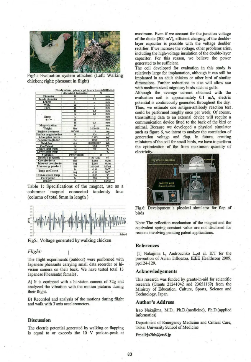
We attached the developed coil to chickens and pheasants and recorded the electric potential generated as the chicken walked and the pheasant
flew. ·
Fig2.: A magnet inside and set OPAMP(AD623) for the differential amplification
OPAMP
A D623
NMMM M GMBBBセセセ
MN セ@
V
o=(I+
セセZョIカ
」@
Vo
L---,...;....,..:=+==----, •• ,- RG=
Iookn
Fig.3: Connection diagram of the differential amplification
Walk:
Fig4.: Evaluation system attached (Left: Walking chicken; right: pheasant in flight)
Nrodvmlum CD5mmx CD1.5mmX2mm IO!II1IIM1.4
OObrn1:ttr•t dtstmatlon Sl
dャッュ・エ・セᄋ@ D 5 mm
Inside rUomt ttr ID 1.5 mm •
Lt11211 L .. mm
\\ldP w mm
Hleh H 2 mm
D 0.1 mm
ID 0.1 mm
Error L mm
+/- w mm
H 0.1 mm
!\lat!nt ttzal on M 2 mm
I . \\'tl•ht Net 0.000268 J«l
Sut·fare trt>atmrnt N iCuNi 12 um
ISurroce moolmlucllot B 304 mT
Adsor >lion power F . 0.383 kar
Oppolntmoe:lnduc Bd 709.2 mT
Totolnux <DO 0.00001267 WI>
rnPifl<ltnt Pc 1.53 Pc
Unll<'r limit ttm Tw oo· "C
owernm ttrmn Tw ·c
1\fotttiols NtO<Ytn urn , 35
Kts t un mn2net c Br· 1170-1220 mT
Oti"C ョ セ@ Ol'Ce Hcb i:; B6B kA/m
In lf'l't llt COt'l"C Vt: 0 He' i:;955 kA/m
1 Mox e nerl!_\' PI'O! uct BH 263-287 kJ/ml
Ttmp cotrrlcit nl He· Br -0.12 %/"C
-0.55 - %rc
IHtat-re!ri srnnt rrm Tw :i BO "C
'II' ti>OIIll Te 310 "C
J.Jtll!llY 7.5 ko/m3
Table 1: Specifications of the magnet, use as a columnar magnet connected tandemly four (column oftotal8mm in length)
M セ@
セ@ ᄋセセセセセセセセセセセセセセ@
'f: ·
___
MM ᄋセZ@
" .
FigS.: Voltage generated by walking chicken
Flight:
'
The flight experiments· .(outdoor) were performed with
Japanese pheasants carrying small data recorder or hi7
vision camera on their back. We have tested total 13 Japanese Pheasants( female).
A) It is equipped with a hi-vision camera of 32g and
analyzed the vibration with the motion pictures during their flight. ·
B) Recorded and analysis of the motions during flight and walk with 3 axis accelerometers.
Discussion
The electric potential generated by walking or flapping is equal to or exceeds the 10 V peak-to-peak at
83
maximum. Even if we account for the junction voltage of the diode (300 m V), efficient charging of the double-layer capacitor is possible with the voltage doubler
rectifier. If we increase the voltage, other problems arise,
including the high7voltage insulation of the double-layer
capacitor. For this reason, we believe the power generated to be sufficient.
The coil developed for evaluation in this study is relatively large for implantation, although it can still be implanted in an adult chicken or other bird of similar dimensions. Further reductions in size will allow use with medium-sized migratory birds such as gulls. Although the average current obtained with the
evaluation coil is approximately 0.1 mA, electric
potential is continuously generated throughout the day Thus, we estimate one antigen-antibody reaction 'test . could be performed roughly once per week. Of course, transmitting data to . an external device will require a communication device fitted to the _back of the bird or animal. Because we developed a physical simulator such as figure 6,_ we intent to analyze the correlation of
generation voltage and flap. In future, creating
miniature of the coil for small birds, we have to perform the optimization · of tbe froni maximum quantity of
Fig.6: Development ·a physical simulator for flap of birds
Note: · The reflection 'mechanism of the magnet and the equivalent spring constant value are not disclosed for reasons involving pending patent applications.
References
[1] Nakajima I., Androuchko L.,et al. ICT for the prevention of Avian Influenza. IEEE Healthcom 2009,
pp:124-129. '
Acknowledgements
This research was funded by grants-in-aid for scientific research (Grants 21241042 and 23651169) from the Ministry of Education, Culture, Sports, Science and Technology, Japan.
Author's Address
Isao Nakajima, M.D., Ph.D.(medicine), Ph.D.(applied informatics)
Department of Emergency Medicine and Critical Care, Tokai University School of M edicine