[Issue No.]
GOT-A-0009-J
[Page]
1/42
[Title]
Precautions when Replacing GOT-A900 Series with GOT1000 Series
[Date of Issue]
Ver. J: May 2015 (First Edition: September 2005)
[Relevant Models]
GOT-A900 Series
TECHNICAL BULLETIN
Thank you for your continued support of Mitsubishi Graphic Operation Terminal (GOT).
We released GOT1000 series with high functions and performance as an alternative of GOT-A900 series in 2004. We highly recommend that you replace GOT-A900 series with GOT1000 series for using new sophisticated features.
Table of Contents
1. Requests for customers ... 2
2. Selection of GOT ... 2
3. Monitor screen data ... 5
3.1 Common functions of GOT-A900 series ... 6
3.1.1 Functions that require new settings ... 6
3.1.2 Printers ... 6
3.1.3 RGB output display ... 7
3.2 Precautions for replacing A951GOT (without -M3) with GOT1000 series ... 7
3.3 Functions only related to A960GOT-EB□(-EU) ... 8
3.3.1 Functions that require changes ... 8
3.4 Change of the utility call key setting ... 10
4. Communication ... 11
4.1 Replacing the GOT-A900 series (connected by the A bus connection) with the GOT1000 series... 11
4.1.1 Settings of the GOT and PLC ... 11
4.1.2 Connection type ... 12
5. Communication units and options ... 21
5.1 List of replacement models ... 21
5.2 Units that require new setting method ... 23
5.3 Communication units and options without replaceable models ... 23
5.4 Replacing the GOT-A900 series connected to the MELSECNET(Ⅱ) or MELSECNET/B network system with the GOT1000 series ... 24
5.4.1 Replacing the network in the entire system with the MELSECNET/H network system ... 24
5.4.2 Changing the connection type between the programmable controller and the GOT without change of the network in the entire system ... 24
5.5 Replacing the GOT-A900 series connected to the MELSECNET/10 (programmable controller to programmable controller optical loop/coaxial bus) network system with the GOT1000 series ... 26
5.6 When using the RUN/OUTPUT terminal of the GOT-A900 series power supply ... 26
6. Cables ... 27
6.1 Bus connection cables ... 27
6.1.1 Replacing GOT when using multiple units of bus connection ... 30
6.2 RS-232 cable ... 30
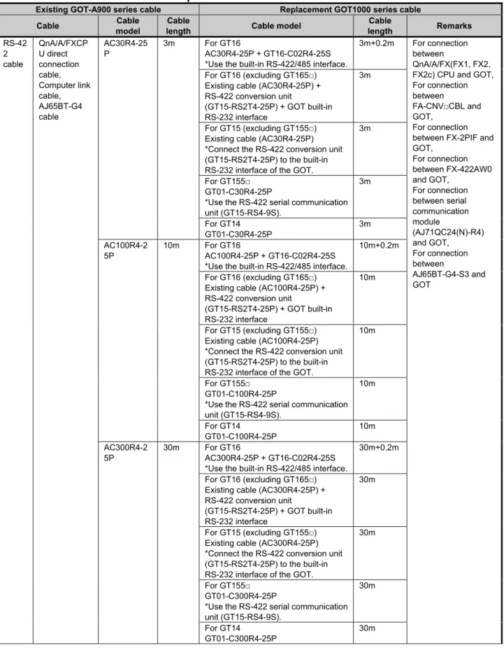
6.3 RS-422 cable ... 31
6.4 Network cable MELSECNET/10 Ethernet, and CC-Link ... 32
6.5 Other cables ... 32
7. Mounting intervals ... 33
7.1 Downward dimension (A dimension) ... 34
7.1.1 Bus connection ... 34
7.2 Depth dimension (F dimension) ... 36
7.2.1 Bus connection ... 36
7.2.2 Printer connection ... 38
[Issue No.]
GOT-A-0009-J
[Page]
2/42
[Title]
Precautions when Replacing GOT-A900 Series with GOT1000 Series
[Date of Issue]
Ver. J: May 2015 (First Edition: September 2005)
[Relevant Models]
GOT-A900 Series
TECHNICAL BULLETIN
1. Requests for customers
We released GOT1000 series with high functions and performance as an alternative of GOT-A900 series in 2004. We highly recommend that you replace GOT-A900 series with GOT1000 series for using new sophisticated features.
For the replacement models, refer to "Table 2-1 Recommended replacement GOT models of the GOT1000 series" in Chapter 2 below.
In the table, some models are introduced as recommended models due to less restriction on their replacement with the GOT1000 series. There may be some other models that you can select depending on their system environment. Therefore, we recommend you to select appropriate models by carefully considering the range of performance in current systems.
2. Selection of GOT
Select a GOT model.
When you replace GOT-A900 series with GOT1000 series, some GOTs require the change of the panel cutting dimensions. If you have difficulty to change the panel cutting dimensions, use the attachment.
The following table shows the recommended replacement GOT models of the GOT1000 series. For the precautions on replacement, refer to each chapter and section.
When you use GOT1000 series shown below, the required drawing software and the drawing software version differ according to the model and functions. Prepare a compatible version of the drawing software.
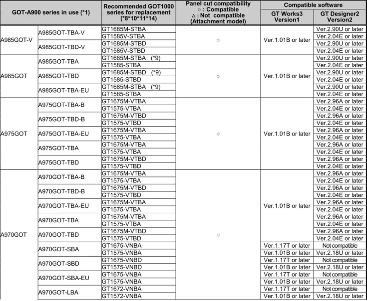
Table 2-1 Recommended replacement GOT models of the GOT1000 series
GOT-A900 series in use (*1)
Recommended GOT1000 series for replacement
(*8*10*11*14)
Panel cut compatibility ○ : Compatible : Not compatible (Attachment model)
Compatible software GT Works3
Version1
GT Designer2 Version2
A985GOT-V
A985GOT-TBA-V GT1685M-STBA
○ Ver.1.01B or later
Ver.2.90U or later
GT1585V-STBA Ver.2.04E or later
A985GOT-TBD-V GT1685M-STBD Ver.2.90U or later
GT1585V-STBD Ver.2.04E or later
A985GOT
A985GOT-TBA GT1685M-STBA (*9)
○ Ver.1.01B or later
Ver.2.90U or later
GT1585-STBA Ver.2.04E or later
A985GOT-TBD GT1685M-STBD (*9) Ver.2.90U or later
GT1585-STBD Ver.2.04E or later
A985GOT-TBA-EU GT1685M-STBA (*9) Ver.2.90U or later
GT1585-STBA Ver.2.04E or later
A975GOT
A975GOT-TBA-B GT1675M-VTBA
○ Ver.1.01B or later
Ver.2.96A or later
GT1575-VTBA Ver.2.04E or later
A975GOT-TBD-B GT1675M-VTBD Ver.2.96A or later
GT1575-VTBD Ver.2.04E or later
A975GOT-TBA-EU GT1675M-VTBA Ver.2.96A or later
GT1575-VTBA Ver.2.04E or later
A975GOT-TBA GT1675M-VTBA Ver.2.96A or later
GT1575-VTBA Ver.2.04E or later
A975GOT-TBD GT1675M-VTBD Ver.2.96A or later
GT1575-VTBD Ver.2.04E or later
A970GOT
A970GOT-TBA-B GT1675M-VTBA
○
Ver.1.01B or later
Ver.2.96A or later
GT1575-VTBA Ver.2.04E or later
A970GOT-TBD-B GT1675M-VTBD Ver.2.96A or later
GT1575-VTBD Ver.2.04E or later
A970GOT-TBA-EU GT1675M-VTBA Ver.2.96A or later
GT1575-VTBA Ver.2.04E or later
A970GOT-TBA GT1675M-VTBA Ver.2.96A or later
GT1575-VTBA Ver.2.04E or later
A970GOT-TBD GT1675M-VTBD Ver.2.96A or later
GT1575-VTBD Ver.2.04E or later
A970GOT-SBA GT1675-VNBA Ver.1.17T or later Not compatible
GT1575-VNBA Ver.1.01B or later Ver.2.18U or later
A970GOT-SBD GT1675-VNBD Ver.1.17T or later Not compatible
GT1575-VNBD Ver.1.01B or later Ver.2.18U or later
A970GOT-SBA-EU GT1675-VNBA Ver.1.17T or later Not compatible
GT1575-VNBA Ver.1.01B or later Ver.2.18U or later
[Issue No.]
GOT-A-0009-J
[Page]
3/42
[Title]
Precautions when Replacing GOT-A900 Series with GOT1000 Series
[Date of Issue]
Ver. J: May 2015 (First Edition: September 2005)
[Relevant Models]
GOT-A900 Series
TECHNICAL BULLETIN
GOT-A900 series in use (*1)
Recommended GOT1000 series for replacement
(*8*10*11*14)
Panel cut compatibility ○ : Compatible : Not compatible (Attachment model) Compatible software GT Works3 Version1 GT Designer2 Version2 A970GOT
A970GOT-LBA GT1662-VNBA (GT15-60ATT-97) Ver.1.17T or later Not compatible
GT1562-VNBA Ver.1.01B or later Ver.2.18U or later
A970GOT-LBD
GT1672-VNBD
○ Ver.1.17T or later Not compatible
GT1572-VNBD Ver.1.01B or later Ver.2.18U or later
GT1662-VNBD
(GT15-60ATT-97) Ver.1.17T or later Not compatible
GT1562-VNBD Ver.1.01B or later Ver.2.18U or later
A970GOT-LBA-EU
GT1672-VNBA
○ Ver.1.17T or later Not compatible
GT1572-VNBA Ver.1.01B or later Ver.2.18U or later
GT1662-VNBA
(GT15-60ATT-97) Ver.1.17T or later Not compatible
GT1562-VNBA Ver.1.01B or later Ver.2.18U or later
A960GOT
A960GOT-EBA GT1662-VNBA (*12)
(GT15-60ATT-96)
Ver.1.17T or later Not compatible GT1562-VNBA (*12) Ver.1.01B or later Ver.2.18U or later A960GOT-EBD GT1662-VNBD (*12) Ver.1.17T or later Not compatible
GT1562-VNBD (*12) Ver.1.01B or later Ver.2.18U or later A960GOT-EBA-EU GT1662-VNBA (*12) Ver.1.17T or later Not compatible
GT1562-VNBA (*12) Ver.1.01B or later Ver.2.18U or later A956WGOT A956WGOT-TBD GT1655-VTBD (*13) (GT15-50ATT-95W) Ver.1.28E or later Not compatible
GT1555-VTBD (*13) Ver.1.01B or later Ver.2.58L or later
A956GOT
A956GOT-TBD-M3 GT1555-QTBD
○
Ver.1.01B or later Ver.2.32J or later
A956GOT-TBD GT1555-QTBD Ver.1.01B or later Ver.2.32J or later
A956GOT-SBD-M3-B GT1555-QSBD
Ver.1.01B or later Ver.2.32J or later A956GOT-SBD-B GT1555-QSBD
A956GOT-SBD-M3 GT1555-QSBD A956GOT-SBD GT1555-QSBD A956GOT-LBD-M3 GT1550-QLBD
A956GOT-LBD GT1550-QLBD Ver.1.01B or later Ver.2.32J or later
A953GOT
A953GOT-TBD-M3
GT1555-QTBD (*3)
○
Ver.1.01B or later Ver.2.32J or later GT1455-QTBD
Ver.1.37P or later Not compatible GT1455-QTBDE
A953GOT-TBD
GT1555-QTBD (*3) Ver.1.01B or later Ver.2.32J or later GT1455-QTBD
Ver.1.37P or later Not compatible GT1455-QTBDE (*7)
A953GOT-SBD-M3-B GT1555-QSBD (*3)
Ver.1.01B or later Ver.2.32J or later A953GOT-SBD-B GT1555-QSBD (*3)
A953GOT-SBD-M3 GT1555-QSBD (*3) A953GOT-SBD GT1555-QSBD (*3) A953GOT-LBD-M3
GT1550-QLBD (*3) GT1450-QMBD
Ver.1.118Y or later Not compatible GT1450-QMBDE (*7)
A953GOT-LBD
GT1550-QLBD (*3) Ver.1.01B or later Ver.2.32J or later GT1450-QMBD
Ver.1.118Y or later Not compatible GT1450-QMBDE (*7)
A951GOT
A951GOT-QTBD-M3 GT1555-QTBD (*4)
○ Ver.1.01B or later Ver.2.32J or later A951GOT-QTBD GT1555-QTBD (*2, *4)
A951GOT-QSBD-M3-B GT1555-QSBD (*4) A951GOT-QSBD-B GT1555-QSBD (*2, *4) A951GOT-QSBD-M3 GT1555-QSBD (*4) A951GOT-QSBD GT1555-QSBD (*2, *4) A951GOT-QLBD-M3 GT1550-QLBD (*4) A951GOT-QLBD GT1550-QLBD (*2, *4) A951GOT-TBD-M3 GT1555-QTBD (*5) A951GOT-TBD GT1555-QTBD (*2, *5) A951GOT-SBD-M3-B GT1555-QSBD (*5) A951GOT-SBD-B GT1555-QSBD (*2, *5) A951GOT-SBD-M3 GT1555-QSBD (*5) A951GOT-SBD GT1555-QSBD (*2, *5) A951GOT-LBD-M3 GT1550-QLBD (*5) A951GOT-LBD GT1550-QLBD (*2, *5) A950GOT A950GOT-TBD-M3
GT1555-QTBD (*6)
○ Ver.1.01B or later Ver.2.32J or later
GT1455-QTBD
[Issue No.]
GOT-A-0009-J
[Page]
4/42
[Title]
Precautions when Replacing GOT-A900 Series with GOT1000 Series
[Date of Issue]
Ver. J: May 2015 (First Edition: September 2005)
[Relevant Models]
GOT-A900 Series
TECHNICAL BULLETIN
GOT-A900 series in use (*1)
Recommended GOT1000 series for replacement
(*8*10*11*14)
Panel cut compatibility ○ : Compatible : Not compatible (Attachment model)
Compatible software GT Works3
Version1
GT Designer2 Version2
A950GOT
A950GOT-TBD
GT1555-QTBD (*6)
○
Ver.1.01B or later Ver.2.32J or later GT1455-QTBD
Ver.1.37P or later Not compatible GT1455-QTBDE (*7)
A950GOT-SBD-M3-B GT1555-QSBD (*6)
Ver.1.01B or later Ver.2.32J or later A950GOT-SBD-B GT1555-QSBD (*6)
A950GOT-SBD-M3 GT1555-QSBD (*6) A950GOT-SBD GT1555-QSBD (*6)
A950GOT-LBD-M3
GT1550-QLBD (*6) GT1450-QMBD
Ver.1.118Y or later Not compatible GT1450-QMBDE (*7)
A950GOT-LBD
GT1550-QLBD (*6) Ver.1.01B or later Ver.2.32J or later GT1450-QMBD
Ver.1.118Y or later Not compatible GT1450-QMBDE (*7)
*1 Production of all the GOT-A900 series models was discontinued.
*2 For replacement model, GT11 dedicated to bus connection is also available. For details, refer to Section 3.2.
*3 When replacing, communicate with RS-232 interface of GOT or use RS-232 serial communication unit (GT15-RS2-9P). *4 When replacing, use a Q bus connection unit (GT15-QBUS (2) or GT15-75QBUS (2)L).
*5 When replacing, use an A bus connection unit (GT15-ABUS (2) or GT15-75ABUS (2)L).
*6 When replacing, use an RS-422 serial communication unit (GT15-RS4-9S).Since the RS-422 serial communication unit (GT15-RS4-9S) has a 9-pin connector, replace the cables in present use (AC□R4-25P and others) with the GOT1000 series cables.
*7 On the GT1455-QTBDE and the GT1450-QLBDE, Ethernet connection can also be used with the Ethernet interface. *8 The Sound output function is an option for the GOT1000 series. When using the sound output function of the GOT-A900
series, use the sound output unit (GT15-SOUT) of the GOT1000 series separately.
*9 The RGB output function is an option for the GOT1000 series. When using the CRT output function of the GOT-A900 series, use the RGB output unit (GT16-ROUT) of the GOT1000 series separately.
*10 The GOT1000 series has no RUN/OUTPUT terminal in the power supply section.
When using the RUN/OUTPUT terminal in the power supply section of the GOT-A900 series, consider using the RUN output of the external I/O unit (GT15-DIO or GT15-DIOR). For the details of the external I/O unit, refer to the following. - GT15 External I/O Unit (Positive Common Input/Sink Type Output) User's Manual (IB-0800382) (GT15-DIO) - GT15 External I/O Unit (Negative Common Input/Source Type Output) User's Manual (IB-0800425) (GT15-DIOR) *11 The display section of the GT16 and the GT14 is an analog-resistive type touch panel. When you touch two points or
more simultaneously on the display section, any touch switch located around the center of the touched points may operate. Do not touch two or more points on the display section simultaneously.
*12 The resolution after replacement is changed (from 640 × 400 dots to 640 × 480 dots). *13 The resolution after replacement is changed (from 480 × 234 dots to 640 × 480 dots). *14 For the production status, contact your local sales office for the relevant technical bulletin.
<Others>
For replacing the GOT-A950 Handy series, refer to the following.
[Issue No.]
GOT-A-0009-J
[Page]
5/42
[Title]
Precautions when Replacing GOT-A900 Series with GOT1000 Series
[Date of Issue]
Ver. J: May 2015 (First Edition: September 2005)
[Relevant Models]
GOT-A900 Series
TECHNICAL BULLETIN
3. Monitor screen data
The monitor screen data used for GOT-A900 series are applicable to GOT1000 series by only changing the GOT type as indicated below.
(1) With GT Designer2 Version2 <Procedure>
1) When the data exists on the personal computer, open the GOT-A900 series project data with GT Designer2 Version2.
When the data does not exist in the personal computer, connect GT Designer2 Version2 to the GOT-A900 series, and upload the project data.
2) Change the GOT type on GT Designer2 Version2.
3) With GT Designer2 Version2, install the communication driver, and download the communication settings and the project data to the GOT1000 series.
(2) With GT Works3 Version1 <Procedure>
1) When the data exists on the personal computer, check the storage location for the GOT-900A series project data.
When the data does not exist on the personal computer, connect GT Designer2 Classic, which is contained in GT Designer2 Version2 or GT Works3 Version1, to the GOT-A900 series, and then upload and store the project data.
2) Open the project data described in 1) with GT Works3 Version1, and change the GOT type.
3) With GT Works3 Version1, install the communication driver, and download the communication settings and the project data to the GOT1000 series.
<Precautions>
1) When some functions require new settings and any changes or some functions are unavailable with GOT1000 series, refer to Chapter 3 and consider replacement methods.
2) For the functions unsupported by GOT1000 series, data set for GOT-A900 series is deleted when replacing with GOT1000 series.
3) For using existing data with GOT1000 series, refer to “App3. Utilizing the Existing Data” in the GT Designer2 Version2 Basic Operation/Data Transfer Manual (SH080529ENG).
4) The GT1662-VNBA and the GT1662-VNBD do not support the drawing software GT Designer2 Version□. Open the GOT-A900 series project data with GT Works3 Version1 (Ver1.15R or later), and change the GOT type to GT16**-V(640x480).
5) The GT1655-VTBD do not support the drawing software GT Designer2 Version□. Open the GOT-A900 series project data with GT Works3 Version1 (Ver1.26C or later), and change the GOT type to
GT165*-V(640x480).
6) The GT1455-QTBD and GT1455-QTBDE do not support the drawing software GT Designer2 Version□. Open the GOT-A900 series project data with GT Works3 Version1 (Ver1.34L or later), and change the GOT type to GT14**-Q (320×240).
7) The GT1450-QMBD and GT1450-QMBDE do not support the drawing software, GT Designer2 Version□. Open the GOT-A900 series project data with GT Works3 Version1 (Ver1.118Y or later), and change the GOT type to GT14**-Q (320x240).
[Issue No.]
GOT-A-0009-J
[Page]
6/42
[Title]
Precautions when Replacing GOT-A900 Series with GOT1000 Series
[Date of Issue]
Ver. J: May 2015 (First Edition: September 2005)
[Relevant Models]
GOT-A900 Series
TECHNICAL BULLETIN
3.1 Common functions of GOT-A900 series
3.1.1 Functions that require new settings
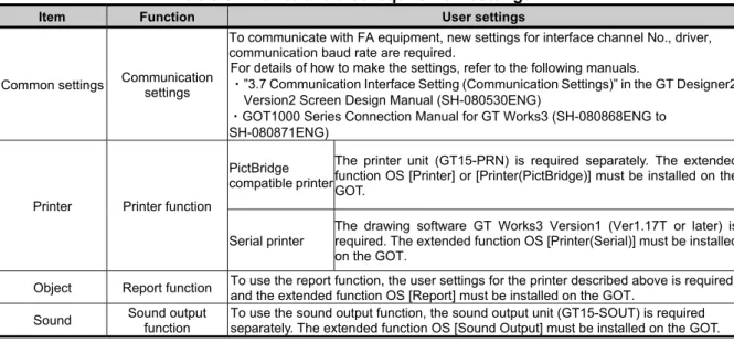
Table 3-1 Functions that require new settings
Item Function User settings
Common settings Communication settings
To communicate with FA equipment, new settings for interface channel No., driver, communication baud rate are required.
For details of how to make the settings, refer to the following manuals.
・”3.7 Communication Interface Setting (Communication Settings)” in the GT Designer2 Version2 Screen Design Manual (SH-080530ENG)
・GOT1000 Series Connection Manual for GT Works3 (SH-080868ENG to SH-080871ENG)
Printer Printer function PictBridge compatible printer
The printer unit (GT15-PRN) is required separately. The extended function OS [Printer] or [Printer(PictBridge)] must be installed on the GOT.
Serial printer
The drawing software GT Works3 Version1 (Ver1.17T or later) is required. The extended function OS [Printer(Serial)] must be installed on the GOT.
Object Report function To use the report function, the user settings for the printer described above is required, and the extended function OS [Report] must be installed on the GOT.
Sound Sound output function
To use the sound output function, the sound output unit (GT15-SOUT) is required separately. The extended function OS [Sound Output] must be installed on the GOT.
3.1.2 Printers
When using printers with the GOT-A900 series, the following are required. (1) Type of printer
The GOT-A900 series supports parallel printers only. The GOT1000 series supports PictBridge compatible printers and serial printers. Therefore, when you replace GOT-A900 series with GOT1000 series, the printer must be replaced. For the validated printer models applicable to the GOT1000 series, refer to TECHNICAL BULLETIN GOT-A-0010 "List of Valid Devices Applicable for GOT1000 Series" on the Mitsubishi Electric Factory Automation Global Website.
(2) Required units
(a) For PictBridge compatible printers
The printer unit GT15-PRN is required separately. (b) For serial printers
No option unit is required. A serial printer is connected to the RS-232 interface of the GOT. (3) Specific print method with alarm history display function
GOT1000 series does not support the function to print the alarm history of the alarm history display function for GOT-A900 series. Save an alarm history file to a CF card in CSV format, and use Microsoft® Excel® and others with a personal computer to print the history.
(4) Report function
With a PictBridge compatible printer, the GOT1000 series supports the GOT-A900 series project data with the report style setting [Log/Page] only. Set the report style to [Log/Page] on the drawing software.
[Issue No.]
GOT-A-0009-J
[Page]
7/42
[Title]
Precautions when Replacing GOT-A900 Series with GOT1000 Series
[Date of Issue]
Ver. J: May 2015 (First Edition: September 2005)
[Relevant Models]
GOT-A900 Series
TECHNICAL BULLETIN
3.1.3 RGB output display
The A985GOT-TBA and the A985GOT-TBD, which are GOT-A900 series, support the RGB output display function. For replacing those models with GOT1000 series, the function is supported by mounting the applicable option unit on the GOT1000 series as shown below.
GOT supporting RGB display Applicable option unit
GT1695M-XTB□ GT1685M-XTB□ GT1675M-□TB□ GT1665M-□TB□
GT16M-ROUT
GT1585V-STB□ GT1575V-STB□
GT15V-75ROUT
3.2 Precautions for replacing A951GOT (without -M3) with GOT1000 series
To replace the GOT-A900 series dedicated to the bus connection (A951GOT (without -M3)) with the GOT1000 series, refer to the following table.
Table 3-2 List of replacement models
GOT-A900 series in use Replacement models Remarks
A951GOT-QTBD GT1155-QTBDQ 5.7”TFT Q bus connection
GT1555-QTBD
A951GOT-QSBD-B GT1155-QSBDQ 5.7”STN color Q bus connection GT1555-QSBD
A951GOT-QSBD GT1155-QSBDQ 5.7”STN color Q bus connection
GT1555-QSBD
A951GOT-QLBD GT1150-QLBDQ 5.7”STN monochrome Q bus connection GT1550-QLBD
A951GOT-TBD GT1155-QTBDA 5.7”TFT A bus connection
GT1555-QTBD
A951GOT-SBD-B GT1155-QSBDA 5.7”STN color A bus connection GT1555-QSBD
A951GOT-SBD GT1155-QSBDA 5.7”STN color A bus connection
GT1555-QSBD
A951GOT-LBD GT1150-QLBDA 5.7”STN monochrome A bus connection
GT1550-QLBD
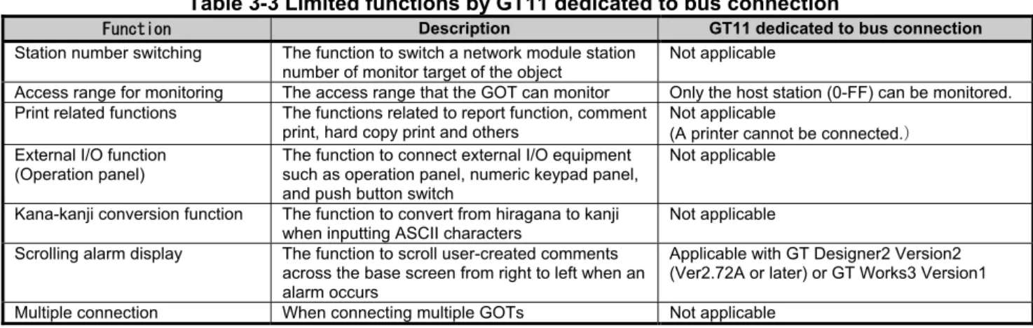
GT11 dedicated to the bus connection does not support the following functions.
Table 3-3 Limited functions by GT11 dedicated to bus connection
Function Description GT11 dedicated to bus connection
Station number switching The function to switch a network module station number of monitor target of the object
Not applicable
Access range for monitoring The access range that the GOT can monitor Only the host station (0-FF) can be monitored. Print related functions The functions related to report function, comment
print, hard copy print and others
Not applicable
(A printer cannot be connected. External I/O function
(Operation panel)
The function to connect external I/O equipment such as operation panel, numeric keypad panel, and push button switch
Not applicable
Kana-kanji conversion function The function to convert from hiragana to kanji when inputting ASCII characters
Not applicable Scrolling alarm display The function to scroll user-created comments
across the base screen from right to left when an alarm occurs
[Issue No.]
GOT-A-0009-J
[Page]
8/42
[Title]
Precautions when Replacing GOT-A900 Series with GOT1000 Series
[Date of Issue]
Ver. J: May 2015 (First Edition: September 2005)
[Relevant Models]
GOT-A900 Series
TECHNICAL BULLETIN
3.3 Functions only related to A960GOT-EB□(-EU)
3.3.1 Functions that require changes
Use GT Designer2 Version2 to change the setting as follows. <Precautions>
This section explains the settings by using GT Designer2 Version2 as an example. When replacing the GOT with the GT1662-VNBA or the GT1662-VNBD, open a project data with GT Works3 Version1 (Ver1.15R or later), and change the GOT type to GT16**-V(640x480).
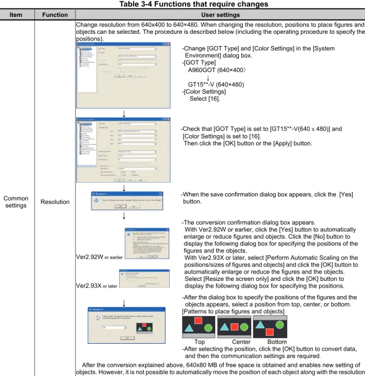
Table 3-4 Functions that require changes
Item Function User settings
Common
settings Resolution
Change resolution from 640x400 to 640×480. When changing the resolution, positions to place figures and objects can be selected. The procedure is described below (including the operating procedure to specify the positions).
↓
↓
↓
Ver2.92W or earlier
Ver2.93X or later
↓
After the conversion explained above, 640x80 MB of free space is obtained and enables new setting of objects. However, it is not possible to automatically move the position of each object along with the resolution change.
-Change [GOT Type] and [Color Settings] in the [System Environment] dialog box.
-[GOT Type] A960GOT (640×400
↓
GT15**-V (640×480) -[Color Settings]
Select [16].
-Check that [GOT Type] is set to [GT15**-V(640x480)] and [Color Settings] is set to [16].
Then click the [OK] button or the [Apply] button.
-After the dialog box to specify the positions of the figures and the objects appears, select a position from top, center, or bottom. [Patterns to place figures and objects]
Top Center Bottom
-After selecting the position, click the [OK] button to convert data, and then the communication settings are required.
-When the save confirmation dialog box appears, click the [Yes] button.
-The conversion confirmation dialog box appears.
With Ver2.92W or earlier, click the [Yes] button to automatically enlarge or reduce figures and objects. Click the [No] button to display the following dialog box for specifying the positions of the figures and the objects.
[Issue No.]
GOT-A-0009-J
[Page]
9/42
[Title]
Precautions when Replacing GOT-A900 Series with GOT1000 Series
[Date of Issue]
Ver. J: May 2015 (First Edition: September 2005)
[Relevant Models]
GOT-A900 Series
TECHNICAL BULLETIN
From the previous page
Item Function User settings
Common
settings Color settings
When changing the GOT type from “A960GOT (640x400): EL color” to “GT15**-V (640x480): 16 color,” the colors of objects on the GT Designer2 Version2 remain yellowish orange (EL color). In addition, when downloading the monitor screen data to the GOT1000 which supports 16 color display, objects are displayed in yellow on the GOT1000 since yellowish orange is not included in the 16 colors. To change the color to other than yellow, change the object color by using batch edit or by replacing colors of objects individually.
The following shows the procedures for the color batch edit.
↓
↓
When using batch conversion of colors, the colors of all bit map images are changed to white. Bit map images are in yellowish orange right after the conversion. The bit map images are changed to white when closing screens and then open the screen data again. To change the colors of bit map images, edit images by using commercially available paint software and others, and then read the images into GT Designer2 Version2.
-Select [Tool]-[Batch Edit]- [Replace Colors] from the menu.
-Select a target screen and click the [Find Now] button. ([All Screen] is selected as a target in this example.)
-All colors in present use are displayed in cells. Click on cells in [New Color] and select colors from the color pallet.
-Click the [Replace] button to change colors.
[Issue No.]
GOT-A-0009-J
[Page]
10/42
[Title]
Precautions when Replacing GOT-A900 Series with GOT1000 Series
[Date of Issue]
Ver. J: May 2015 (First Edition: September 2005)
[Relevant Models]
GOT-A900 Series
TECHNICAL BULLETIN
3.4 Change of the utility call key setting
While the user-created screen is displayed, touching the utility call key displays the main menu.
For the GT15 models, the utility call key is set in the position of simultaneous 2-point press on the GOT screen upper-left and upper-right corners. For the GT16 and the GT14 models, note that the utility call key is set in the position of 1-point press on the GOT screen upper-left corner.
The position of the utility call key can be changed using the GOT utility, GT Designer3, or GT Designer2. The following shows the position of the utility call key for the GT15 models set at factory default.
Model Utility call key (factory default)
GT1585
GT157□
GT156□
GT155□
Simultaneous 2-point press on the GOT screen upper-left and upper-right corners
Menu call key Simultaneous 2-point touch
The following shows the position of the utility call key for the GT16 and the GT14 models set at factory default.
Model Utility call key
GT16 GT14
1-point press on the GOT screen upper-left corner
Menu call key 1-point touch on the
[Issue No.]
GOT-A-0009-J
[Page]
11/42
[Title]
Precautions when Replacing GOT-A900 Series with GOT1000 Series
[Date of Issue]
Ver. J: May 2015 (First Edition: September 2005)
[Relevant Models]
GOT-A900 Series
TECHNICAL BULLETIN
4. Communication
4.1 Replacing the GOT-A900 series (connected by the A bus connection) with the GOT1000 series
No further orders for all the models of the A bus connection unit will be accepted in and after January 2015, and the production will be discontinued in and after February 2015. When the GOT-A900 series is connected by the A bus connection, the connection type must be changed or the PLC must be replaced.
To replace the PLC, refer to the following Technical Bulletin.
➟ Production discontinuation of MELSEC-AnS/QnAS (small type) series and MELSEC-I/OLINK (FA-A-0142)
Production discontinuation of MELSEC-A/QnA (large type) series (T99-0050) To change the A bus connection to another connection type, refer to the following.
➟ 4.1.1 Settings of the GOT and PLC 4.1.2 Connection type
4.1.1 Settings of the GOT and PLC
When changing the connection type, check the settings of the PLC and GOT.
(1) PLC
When the GOT connected by the bus connection is removed or a communication unit is added to the PLC, the PLC may require new settings. According to the PLC configuration, check the parameter setting (including I/O assignment) and I/O numbers in the sequence program.
(2) GOT
Change the controller setting. *1
When changing the connection type to the network connection (excluding the Ethernet connection), set the network number and station number in the device number of each object. *2
*1 Example of the controller setting
[Issue No.]
GOT-A-0009-J
[Page]
12/42
[Title]
Precautions when Replacing GOT-A900 Series with GOT1000 Series
[Date of Issue]
Ver. J: May 2015 (First Edition: September 2005)
[Relevant Models]
GOT-A900 Series
TECHNICAL BULLETIN
*2 Setting of the network number and station number
To monitor D0 of the CPU in the network number 1 and station number 2
4.1.2 Connection type
(1) Changing the connection type to the serial connection
(a) Direct Connection to CPU
Connect the GOT in the following configuration.
PLC GOT
Connection cable
1) When connecting the GOT with MELSEC-A (ACPU, AnCPU, AnSCPU) or MELSEC-QnA (QnACPU, QnASCPU)
PLC
Cable model *1
GOT
Model name Communication
type Option device Model
MELSEC-A(ACPU) *2
MELSEC-A(AnCPU) *2
MELSEC-A(AnSCPU) *2
MELSEC-Q(QnACPU) MELSEC-Q(QnASCPU)
RS-422 GT01-C30R4-25P(3m) GT01-C100R4-25P(10m)
GT01-C200R4-25P(20m) GT01-C300R4-25P(30m)
GT16-C02R4-9S GT16
GT15-RS2T4-9P *3 GT16, GT15
GT15-RS4-9S
(Built into GOT) GT14
*1 If the connection distance exceeds 30m, consider changing the connection type to the network connection.
*2 When monitoring AnNCPU, A0J2HCPU, A2CCPU or A2SCPU, only the following or later software version is used to write to the CPU.
・ AnNCPU(S1) with link: Version L or later, AnNCPU(S1) without link: Version H or later
・ A0J2HCPU (with/without link): Version E or later
・ A0J2HCPU-DC24: Version B or later
・ A2CCPU, A2SCPU: Version H or later
[Issue No.]
GOT-A-0009-J
[Page]
13/42
[Title]
Precautions when Replacing GOT-A900 Series with GOT1000 Series
[Date of Issue]
Ver. J: May 2015 (First Edition: September 2005)
[Relevant Models]
GOT-A900 Series
TECHNICAL BULLETIN
(b) Computer Link Connection
Connect the GOT in the following configuration.
Changing the connection type to the computer link connection requires a computer link module on the PLC side.
Computer link module
PLC GOT
Connection cable
1) When connecting the GOT with MELSEC-A (ACPU, AnCPU) *1 PLC
Cable model *2*3
GOT Computer link
module
Communication
type Option device Model
AJ71UC24 *5 RS-232 GT09-C30R2-25P(3m)
Cables prepared by the user (max.: 15m)
(Built into GOT) GT16, GT15, GT14 GT15-RS2-9P GT16, GT15 RS-422 Cables prepared by the user
(max.: 500m)
(Built into GOT) GT16 GT09-C30R4-6C(3m)
GT09-C100R4-6C(10m) GT09-C200R4-6C(20m) GT09-C300R4-6C(30m) Cables prepared by the user (max.: 500m)
GT16-C02R4-9S GT16 GT15-RS2T4-9P *4 GT16, GT15 GT15-RS4-9S
(Built into GOT) GT14 *1 The computer link module version U or later supports the A2SCPU(S1), A2SHCPU(S1), A1SHCPU,
A1SJHCPU and A0J2HCPU.
In addition, A0J2-C214-S1 (A0J2HCPU-dedicated computer link module) cannot be used. *2 For cables prepared by the user, refer to the following.
➟ GOT2000 Series Connection Manual (Mitsubishi Products) For GT Works3 Version1 *3 If the connection distance exceeds 30m, consider changing the connection type to the connection
using a cable prepared by the user or the network connection.
*4 Connect it to the RS-232 interface (built into GOT). It cannot be mounted on GT1655 and GT155□. *5 Production of this module has been discontinued.
2) When connecting the GOT with MELSEC-A (AnSCPU *1, A0J2HCPU *1, A2CCPU) PLC
Cable model *2*3
GOT Computer link
module
Communication
type Option device Model
A1SJ71UC24-R2 *5 A1SJ71C24-R2 *5 A1SJ71UC24-PRF *5 A1SJ71C24-PRF *5
RS-232 GT09-C30R2-29P(3m) Cables prepared by the user (max.: 15m)
(Built into GOT) GT16, GT15, GT14 GT15-RS2-9P GT16, GT15 A1SJ71UC24-R4 *5
A1SJ71C24-R4 *5
RS-422 Cables prepared by the user (max.: 500m)
(Built into GOT) GT16 GT09-C30R4-6C(3m)
GT09-C100R4-6C(10m) GT09-C200R4-6C(20m) GT09-C300R4-6C(30m) Cables prepared by the user (max.: 500m)
GT16-C02R4-9S GT16 GT15-RS2T4-9P *4 GT16
[Issue No.]
GOT-A-0009-J
[Page]
14/42
[Title]
Precautions when Replacing GOT-A900 Series with GOT1000 Series
[Date of Issue]
Ver. J: May 2015 (First Edition: September 2005)
[Relevant Models]
GOT-A900 Series
TECHNICAL BULLETIN
*1 The computer link module version U or later supports the A2SCPU(S1), A2SHCPU(S1), A1SHCPU, A1SJHCPU and A0J2HCPU.
In addition, A0J2-C214-S1 (A0J2HCPU-dedicated computer link module) cannot be used. *2 For cables prepared by the user, refer to the following.
➟ GOT2000 Series Connection Manual (Mitsubishi Products) For GT Works3 Version1 *3 If the connection distance exceeds 30m, consider changing the connection type to the connection
using a cable prepared by the user or the network connection.
*4 Connect it to the RS-232 interface (built into GOT). It cannot be mounted on GT1655 and GT155□. *5 Production of this module has been discontinued.
3) When connecting the GOT with MELSEC-QnA (QnACPU) PLC
Cable model *1*2
GOT
Serial communication /Computer link module
Communication
type Option device Model
AJ71QC24 *5 AJ71QC24N *5 AJ71QC24-R2 *5 AJ71QC24N-R2 *5
RS-232 GT09-C30R2-25P(3m) Cables prepared by the user (max.: 15m)
(Built into GOT) GT16, GT15, GT14 GT15-RS2-9P GT16, GT15 AJ71QC24-R4 *5
AJ71QC24N-R4 *5
RS-422 GT01-C30R4-25P(3m) GT01-C100R4-25P(1m)
GT01-C200R4-25P(20m) GT01-C300R4-25P(30m)
GT16-C02R4-9S GT16 GT15-RS2T4-9P *3 GT16, GT15 GT15-RS4-9S
(Built into GOT) GT14 AJ71QC24 *5
AJ71QC24N *5 AJ71QC24-R4 *5 AJ71QC24N-R4 *5
RS-422 Cables prepared by the user (max.: 1200m)
(Built into GOT) GT16 GT09-C30R4-6C(3m)
GT09-C100R4-6C(10m) GT09-C200R4-6C(20m) GT09-C300R4-6C(30m) Cables prepared by the user (max.: 1200m)
GT16-C02R4-9S GT16 GT15-RS2T4-9P *3 GT16, GT15 GT15-RS4-9S
(Built into GOT) GT14
AJ71UC24 *4*5 RS-232 GT09-C30R2-25P(3m)
Cables prepared by the user (max.: 15m)
(Built into GOT) GT16, GT15, GT14 GT15-RS2-9P GT16, GT15 AJ71UC24 *4*5 RS-422 Cables prepared by the user
(max.: 500m)
(Built into GOT) GT16 GT09-C30R4-6C(3m)
GT09-C100R4-6C(10m) GT09-C200R4-6C(20m) GT09-C300R4-6C(30m) Cables prepared by the user (max.: 500m)
GT16-C02R4-9S GT16 GT15-RS2T4-9P *3 GT16, GT15 GT15-RS4-9S
(Built into GOT) GT14 *1 For cables prepared by the user, refer to the following.
➟ GOT2000 Series Connection Manual (Mitsubishi Products) For GT Works3 Version1 *2 If the connection distance exceeds 30m, consider changing the connection type to the connection
using a cable prepared by the user or the network connection.
*3 Connect it to the RS-232 interface (built into GOT). It cannot be mounted on GT1655 and GT155□. *4 The usable device numbers correspond to the device range of AnACPU.
[Issue No.]
GOT-A-0009-J
[Page]
15/42
[Title]
Precautions when Replacing GOT-A900 Series with GOT1000 Series
[Date of Issue]
Ver. J: May 2015 (First Edition: September 2005)
[Relevant Models]
GOT-A900 Series
TECHNICAL BULLETIN
4) Whenconnecting the GOT with MELSEC-QnA (QnASCPU) PLC
Cable model *1*2
GOT
Serial communication /Computer link module
Communication
type Option device Model
A1SJ71QC24 *5 A1SJ71QC24N *5 A1SJ71QC24N1 *5 A1SJ71QC24-R2 *5 A1SJ71QC24N-R2 *5 A1SJ71QC24N1-R2 *5
RS-232 GT09-C30R2-9P(3m) Cables prepared by the user (max.: 15m)
(Built into GOT) GT16, GT15, GT14 GT15-RS2-9P GT16, GT15
A1SJ71QC24 *5 A1SJ71QC24N *5 A1SJ71QC24N1 *5
RS-422 Cables prepared by the user (max.: 1200m)
(Built into GOT) GT16 GT09-C30R4-6C(3m)
GT09-C100R4-6C(10m) GT09-C200R4-6C(20m) GT09-C300R4-6C(30m) Cables prepared by the user (max.: 1200m)
GT16-C02R4-9S GT16 GT15-RS2T4-9P *3 GT16, GT15 GT15-RS4-9S
(Built into GOT) GT14 A1SJ71UC24-R2 *4*5
A1SJ71C24-R2 *4*5 A1SJ71UC24-PRF *4*5
A1SJ71C24-PRF *4*5
RS-232 GT09-C30R2-29P(3m) Cables prepared by the user (max.: 15m)
(Built into GOT) GT16, GT15, GT14 GT15-RS2-9P GT16, GT15
A1SJ71UC24-R4 *4*5 A1SJ71C24-R4 *4*5
RS-422 Cables prepared by the user (max.: 500m)
(Built into GOT) GT16 GT09-C30R4-6C(3m)
GT09-C100R4-6C(10m) GT09-C200R4-6C(20m) GT09-C300R4-6C(30m) Cables prepared by the user (max.: 500m)
GT16-C02R4-9S GT16 GT15-RS2T4-9P *3 GT16, GT15 GT15-RS4-9S
(Built into GOT) GT14 *1 For cables prepared by the user, refer to the following.
➟ GOT2000 Series Connection Manual (Mitsubishi Products) For GT Works3 Version1 *2 If the connection distance exceeds 30m, consider changing the connection type to the connection
using a cable prepared by the user or the network connection.
*3 Connect it to the RS-232 interface (built into GOT). It cannot be mounted on GT1655 and GT155□. *4 The usable device numbers correspond to the device range of AnACPU.
[Issue No.]
GOT-A-0009-J
[Page]
16/42
[Title]
Precautions when Replacing GOT-A900 Series with GOT1000 Series
[Date of Issue]
Ver. J: May 2015 (First Edition: September 2005)
[Relevant Models]
GOT-A900 Series
TECHNICAL BULLETIN
(2) Changing the connection type to the network connection
(a) MELSECNET/10 Connection
Connect the GOT in the following configuration.
Changing the connection type to the MELSECNET/10 connection requires a MELSECNET/10 network module on the PLC side.
The GOT side requires a MELSECNET/H communication unit (used in the MELSECNET/10 mode).
MELSECNET/10
network module GOT
Connection cable PLC
1) When connecting the GOT with MELSEC-A (AnCPU *1, AnSCPU *1) (optical loop system) PLC
Cable model
GOT MELSECNET/H
network module
Communication
type Option device Model
AJ71LP21 *4 A1SJ71LP21
MELSECNET/10 Optical fiber cable GT15-J71LP23-25 *2 GT16, GT15 GT15-75J71LP23-Z *3 GT15
*1 The following PLCs can be connected: A2UCPU, A2UCPU-S1, A3UCPU, A4UCPU, A2USCPU, A2USCPU-S1, and A2USHCPU-S1.
*2 Set the MELSECNET/10 mode in the controller setting. *3 Not available for the GT155□.
*4 Production of this module has been discontinued.
2) When connecting the GOT with MELSEC-QnA (QnACPU, QnASCPU) (optical loop system) PLC
Cable model
GOT MELSECNET/H
network module
Communication
type Option device Model
AJ71QLP21 *3 AJ71QLP21S *3 A1SJ71QLP21 A1SJ71QLP21S *3
MELSECNET/10 Optical fiber cable GT15-J71LP23-25 *1 GT16, GT15 GT15-75J71LP23-Z *2 GT15
*1 Set the MELSECNET/10 mode in the controller setting. *2 Not available for the GT155□.
*3 Production of this module has been discontinued.
3) When connecting the GOT with MELSEC-A (AnCPU *1, AnSCPU *1) (coaxial bus system) PLC
Cable model
GOT MELSECNET/H
network module
Communication
type Option device Model
AJ71BR11 *4 A1SJ71BR11
MELSECNET/10 Coaxial cable GT15-J71BR13 *2 GT16, GT15
GT15-75J71BR13-Z *3 GT15 *1 The following PLCs can be connected: A2UCPU, A2UCPU-S1, A3UCPU, A4UCPU, A2USCPU,
A2USCPU-S1, and A2USHCPU-S1.
*2 Set the MELSECNET/10 mode in the controller setting. *3 Not available for the GT155□.
[Issue No.]
GOT-A-0009-J
[Page]
17/42
[Title]
Precautions when Replacing GOT-A900 Series with GOT1000 Series
[Date of Issue]
Ver. J: May 2015 (First Edition: September 2005)
[Relevant Models]
GOT-A900 Series
TECHNICAL BULLETIN
4) When connecting the GOT with MELSEC-QnA (QnACPU, QnASCPU) (coaxial bus system) PLC
Cable model
GOT MELSECNET/H
network module
Communication
type Option device Model
AJ71QBR11 *3 A1SJ71QBR11
MELSECNET/10 Coaxial cable GT15-J71BR13 *1 GT16, GT15
GT15-75J71BR13-Z *2 GT15 *1 Set the MELSECNET/10 mode in the controller setting.
*2 Not available for the GT155□.
*3 Production of this module has been discontinued.
(b) CC-Link Connection (Intelligent Device Station)
Connect the GOT in the following configuration.
Changing the connection type to the CC-Link (intelligent device station) connection requires a CC-Link module on the PLC side.
CC-Link module
PLC GOT
Connection cable
1) When connecting the GOT with MELSEC-A (ACPU *1, AnCPU, AnSCPU) PLC
Cable model
GOT
CC-Link module Communication
type Option device Model
AJ61BT11 *3 A1SJ61BT11
CC-Link (Ver.1) CC-Link dedicated cable GT15-J61BT13 *2 GT16, GT15 GT15-75J61BT13-Z GT15
*1 Only A0J2HCPU, A0J2HCPUP21, A0J2HCPUR21, and A0J2HCPU-DC24 can be connected. *2 Specify Ver.1 as the mode setting in the Communication Settings to use it.
*3 Production of this module has been discontinued.
2) When connecting the GOT with MELSEC-QnA (QnACPU, QnASCPU) PLC
Cable model
GOT
CC-Link module Communication
type Option device Model
AJ61QBT11 *2 A1SJ61QBT11
CC-Link (Ver.1) CC-Link dedicated cable GT15-J61BT13 *1 GT16, GT15 GT15-75J61BT13-Z GT15
[Issue No.]
GOT-A-0009-J
[Page]
18/42
[Title]
Precautions when Replacing GOT-A900 Series with GOT1000 Series
[Date of Issue]
Ver. J: May 2015 (First Edition: September 2005)
[Relevant Models]
GOT-A900 Series
TECHNICAL BULLETIN
(c) Ethernet Connection
Connect the GOT in the following configuration.
Changing the connection type to the Ethernet connection requires an Ethernet module on the PLC side.
Ethernet
module GOT
Connection cable PLC
1) When connecting the GOT with MELSEC-A (AnCPU, AnSCPU)
PLC
Cable model
GOT
Ethernet module Communication
type Option device Model
AJ71E71N3-T *3 AJ71E71N-B5 *3 AJ71E71N-B2 *3 AJ71E71N-T *3 AJ71E71N-B5T *3 AJ71E71-S3 *3 A1SJ71E71N3-T *3 A1SJ71E71N-B5 *3 A1SJ71E71N-B2 *3 A1SJ71E71N-T *3 A1SJ71E71N-B5T *3 A1SJ71E71-B5-S3 *3 A1SJ71E71-B2-S3 *3
Ethernet Twisted pair cable ・10BASE-T ・100BASE-TX
(Built into GOT) GT16 *1, GT14 *2
GT15-J71E71-100 GT15
*1 When connecting GT16 of the function version A to an equipment that meets the 10BASE (-T/2/5) standard, use the switching hub and operate in a 10Mbps/100Mbps mixed environment.
For how to check the function version, refer to the following. ➟ GT16 User's Manual (Hardware)
[Issue No.]
GOT-A-0009-J
[Page]
19/42
[Title]
Precautions when Replacing GOT-A900 Series with GOT1000 Series
[Date of Issue]
Ver. J: May 2015 (First Edition: September 2005)
[Relevant Models]
GOT-A900 Series
TECHNICAL BULLETIN
2) When connecting the GOT with MELSEC-QnA (QnACPU, QnASCPU) PLC
Cable model
GOT
Ethernet module Communication
type Option device Model
AJ71QE71N3-T *3 AJ71QE71N-B5 *3 AJ71QE71N-B2 *3 AJ71QE71N-T *3 AJ71QE71N-B5T *3 AJ71QE71 *3 AJ71QE71-B5 *3 A1SJ71QE71N3-T *3 A1SJ71QE71N-B5 *3 A1SJ71QE71N-B2 *3 A1SJ71QE71N-T *3 A1SJ71QE71N-B5T *3 A1SJ71QE71-B5 *3 A1SJ71QE71-B2 *3
Ethernet Twisted pair cable ・10BASE-T ・100BASE-TX
(Built into GOT) GT16 *1, GT14 *2
GT15-J71E71-100 GT15
*1 When connecting GT16 of the function version A to an equipment that meets the 10BASE (-T/2/5) standard, use the switching hub and operate in a 10Mbps/100Mbps mixed environment.
For how to check the function version, refer to the following. ➟ GT16 User's Manual (Hardware)
*2 GT14 models compatible with Ethernet connection are only GT1455-QTBDE and GT1450-QMBDE. *3 Production of this module has been discontinued.
(3) Changing the connection type when multiple GOTs are connected
Consider the following connection types for the configuration in which the multiple GOTs are connected.
・Network Connection
➟ 2.2.1 ■2 (2) Changing the connection type to the network connection
・Multi-Drop Connection
➟ (a) Multi-Drop Connection
(a) Multi-Drop Connection *1
Connect the GOT in the following configuration.
Changing the connection type to the multi-drop connection requires the following option devices and cables.
GOT GOT
PLC
Varies according to the connection type.
[Issue No.]
GOT-A-0009-J
[Page]
20/42
[Title]
Precautions when Replacing GOT-A900 Series with GOT1000 Series
[Date of Issue]
Ver. J: May 2015 (First Edition: September 2005)
[Relevant Models]
GOT-A900 Series
TECHNICAL BULLETIN
1) When connecting the GOT with MELSEC-A (ACPU, AnCPU, AnSCPU)*1 or MELSEC-QnA (QnACPU *2, QnASCPU)
For the system configuration between the serial multi-drop connection unit and PLC, refer to the items about each connection type.
Multi-Drop Connection Unit
Cable model *3
GOT
Serial Multi-Drop Connection Unit
Communication
type Option device Model
GT01-RS4-M RS-485 Cables prepared by the user
(max.: 15m)
FA-LTBGTR4CBL05(0.5m) FA-LTBGTR4CBL10(1m) FA-LTBGTR4CBL20(2m)
GT16
GT15-RS4-9S GT16, GT15
GT15-RS4-TE GT16, GT15
GT10-9PT5S *4 GT14 (Built into GOT)
GT14-RS2T4-9P *5
*1 These PLCs cannot be connected to the serial multi-drop connection unit in the computer link connection.
*2 Q4ARCPU cannot be connected.
*3 For cables prepared by the user, refer to the following.
➟ GOT2000 Series Connection Manual (Mitsubishi Products) For GT Works3 Version1 *4 Connect it to the RS-422/485 interface (built into GOT).
[Issue No.]
GOT-A-0009-J
[Page]
21/42
[Title]
Precautions when Replacing GOT-A900 Series with GOT1000 Series
[Date of Issue]
Ver. J: May 2015 (First Edition: September 2005)
[Relevant Models]
GOT-A900 Series
TECHNICAL BULLETIN
5. Communication units and options
5.1 List of replacement models
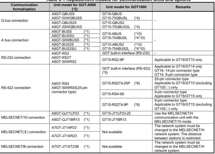
The GOT-A900 series communication units and options cannot be used with the GOT1000 series. For replacing the GOT-A900 series with the GOT1000 series, use the communication units and the options dedicated to the GOT1000 series.
Table 5-1 Replacement models for communication units and options
Communication format/option
Unit model for GOT-A900
(*2) Unit model for GOT1000 Remarks
Q bus connection
A9GT-QBUSS A9GT-50WQBUSS
GT15-QBUS
GT15-75QBUSL (*4) - A9GT-QBUS2S
A9GT-50WQBUSS
GT15-QBUS2
GT15-75QBUS2L (*4)
A bus connection
A9GT-BUSS (*1)
GT15-ABUS (*10) GT15-75ABUSL (*4*10)
- A9GT-BUSSU (*1)
A9GT-50WBUSS (*1)
A9GT-BUS2S (*1) GT15-ABUS2 (*10) GT15-75ABUS2L (*4*10) A9GT-BUS2SU (*1)
RS-232 connection
A9GT-RS2 A9GT-RS2T A9GT-50WRS2
GOT built-in interface (RS-232) -
GT15-RS2-9P Applicable to GT16/GT15 only
RS-422 connection
A9GT-RS4
A9GT-50WRS4(25-pin connector type)
GOT built-in interface (RS-422) (*5)
Applicable to GT16/GT14 only GT16: 14-pin connector type GT14: 9-pin connector type GT15-RS2T4-25P (*8)
25-pin connector type
Applicable to GT16/GT15 (excluding GT155□) only
GT15-RS4-9S 9-pin connector type
Applicable to GT16/GT15 only GT15-RS2T4-9P (*8)
9-pin connector type
Applicable to GT16/GT15 (excluding GT155□) only
MELSECNET/10 connection
A9GT-QJ71LP23 (*1) GT15-J71LP23-25 Use the MELSECNET/H communication unit with the MELSECNET/10 mode. A9GT-QJ71BR13 (*1) GT15-J71BR13
MELSECNET(Ⅱ) connection
A7GT-J71AP23 (*1)
Not available
The network system must be changed to the MELSECNET/H network system. The distance between stations is restricted. A7GT-J71AR23 (*1)
MELSECNET/B connection A7GT-J71AT23B (*1) Not available
[Issue No.]
GOT-A-0009-J
[Page]
22/42
[Title]
Precautions when Replacing GOT-A900 Series with GOT1000 Series
[Date of Issue]
Ver. J: May 2015 (First Edition: September 2005)
[Relevant Models]
GOT-A900 Series
TECHNICAL BULLETIN
From the previous page
Communication format/option
Unit model for GOT-A900
(*10) Unit model for GOT1000 Remarks
CC-Link connection A8GT-J61BT13 (*1)
A8GT-J61BT15 (*1) GT15-J61BT13
For replacing A8GT-J61BT15, change the sequence programs (deleting ladder programs) and the screen settings.
Ethernet connection A9GT-J71E71-T
GOT built-in interface
(Ethernet) Applicable to GT16/GT14 only GT15-J71E71-100 (*6) Applicable to GT15 only
Video/RGB interface unit
A9GT-80V4R1 GT16M-V4R1 - A9GT-80V4 GT16M-V4 A9GT-80R1 GT16M-R2
External I/O interface
A9GT-70KBF
GT15-DIO (*3)
The cable wiring must be changed because of the increase in the number of I/O points and the different interface pin configuration. A8GT-50KBF
Numeric keypad panel A8GT-TK Applicable without replacement
(*9) -
Printer interface A9GT-50PRF (Parallel interface)
GT15-PRN
The printer model must be changed because the GOT1000 series has a USB interface. (*7)
GOT built-in interface (RS-232) The printer model must be changed because the GOT1000 series has a RS-232 interface. (*7)
GT15-RS2-9P
PC card interface unit A1SD59J-MIF Not available G16/GT15: Built-in CF card interface G14: Built-in SD card interface
*1 The GOT-A900 series communication unit has setting switches, including rotary switches. Though the GOT1000 series communication unit does not have rotary switches and others, setting switches is required with software. Therefore, set the switches with the drawing software or the utility. For details, refer to Section 4.2.
*2 Production of all the GOT-A900 series units was discontinued.
*3 Specifications of external power supply voltage, external connection connector shape and others are changed. For details, refer to the GT15 External I/O Unit (Positive Common Input/Sink Type Output) User's Manual (IB-0800382).
*4 The slim model has limitation for combination with other units. To use the slim model with the units for the functions, including the external I/O function, the sound output function, the printer function, and the video/RGB I/O function, use the following units.
- GT15-ABUS (A bus connection 1ch), GT15-ABUS2 (A bus connection 2ch), GT15-QBUS (Q bus connection 1ch), GT15-QBUS2(Q bus connection 2ch)
*5 To download monitor screen data and others from a personal computer to the GOT via the GOT built-in RS-232 interface, the cable must be replaced.
*6 The A9GT-J71E71-T only supports 10Mbps (10BASE-T). However, the GT15-J71E71-100 and the GT16/GT14 built-in interface (Ethernet) support both 10Mbps (10BASE-T) and 100Mbps (100BASE-TX).
The GT1695 and the GT1685 with function version A do not support 10Mbps (10BASE-T).
*7 Since the Centronics interface (AGT-50PRF) is replaced with the USB interface (GT15-PRN) or the RS-232 interface (GOT built-in interface), change the printer model. For the validated printer models applicable to the GOT1000 series, refer to TECHNICAL BULLETIN GOT-A-0010 "List of Valid Devices Applicable for GOT1000 Series" on the Mitsubishi Electric Factory Automation Global Website.
*8 The GT1655 and GT155□ do not support the GT15-RS2T4-25P and GT15-RS2T4-9P.
*9 The external I/O unit (GT15-DIO) and the external I/O unit connection conversion cable (GT15-C03HTB) are required. The GT15-DIOR cannot be used.
*10 No order was accepted after December 31, 2014, and the production was discontinued in January 31, 2015. To replace a GOT-A900 series unit with a GOT1000 series unit, refer to the following and change the A bus connection to another connection type.
[Issue No.]
GOT-A-0009-J
[Page]
23/42
[Title]
Precautions when Replacing GOT-A900 Series with GOT1000 Series
[Date of Issue]
Ver. J: May 2015 (First Edition: September 2005)
[Relevant Models]
GOT-A900 Series
TECHNICAL BULLETIN
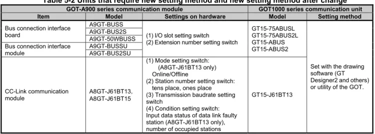
5.2 Units that require new setting method
The communication units for the GOT-A900 series listed below require settings with rotary switches and others on the hardware. However, the communication units for the GOT1000 series do not have rotary switches and others, and settings with the drawing software or the utility are required. For GOT1000 series, refer to the following table.
Table 5-2 Units that require new setting method and new setting method after change
GOT-A900 series communication module GOT1000 series communication unit
Item Model Settings on hardware Model Setting method
Bus connection interface board
A9GT-BUSS
(1) I/O slot setting switch
(2) Extension number setting switch
GT15-75ABUSL GT15-75ABUS2L GT15-ABUS GT15-ABUS2
Set with the drawing software (GT Designer2 and others) or utility of the GOT. A9GT-BUS2S
A9GT-50WBUSS Bus connection interface
module
A9GT-BUSSU A9GT-BUS2SU
CC-Link communication module
A8GT-J61BT13 A8GT-J61BT15
(1) Mode setting switch: (A8GT-J61BT13 only) Online/Offline
(2) Station number setting switch: tens place, ones place (3) Transmission baudrate setting switch
(4) Condition setting switch: Input data status of data link faulty station (A8GT-J61BT13 only), number of occupied stations
GT15-J61BT13
5.3 Communication units and options without replaceable models
The communication units and options for the GOT-A900 series listed below do not have alternative models to be compatible with the GOT1000 series. If replacing with the GOT1000 series is difficult, obtain a sufficient number of spare units.
Table 5-3 Communication modules and options without replaceable models and alternative plans
Category Item Model Alternative plan
Communication module
Data link unit for MELSECNET (II) network system
A7GT-J71AP23 Replacing with the MELSECNET/H network system (GOT1000 series communication unit model: GT15-J71BR13/GT15-J71LP23-25) is recommended. (Section 4.4)
A7GT-J71AR23 Data link unit for MELSECNET/B
network system
A7GT-J71AT23B CC-Link communication module
(remote device station)
A8GT-J61BT15 Replacing with the CC-Link (intelligent device station) communication unit (GOT1000 series communication unit model: GT15-J61BT13) is recommended. (*1)
*1 -Maximum number of connected units is reduced from 32 to 26. When connecting more than 26 units, consider adding a master station to support the system.
[Issue No.]
GOT-A-0009-J
[Page]
24/42
[Title]
Precautions when Replacing GOT-A900 Series with GOT1000 Series
[Date of Issue]
Ver. J: May 2015 (First Edition: September 2005)
[Relevant Models]
GOT-A900 Series
TECHNICAL BULLETIN
5.4 Replacing the GOT-A900 series connected to the MELSECNET(Ⅱ) or MELSECNET/B network system with the GOT1000 series
When the GOT-A900 series is used in the MELSECNET(Ⅱ) or MELSECNET/B network system, the GOT-A900 series cannot be replaced with the GOT1000 series since the GOT1000 series does not support the
MELSECNET(Ⅱ) or MELSECNET/B connection.
Consider the replacement with any of the following method.
-Change the MELSECNET(Ⅱ) or MELSECNET/B network system in the entire system to the MELSECNET/H network system, and replace the GOT-A900 series with the GOT1000 series.
-Without the change of the MELSECNET(Ⅱ) or MELSECNET/B network system in the entire system, change the connection type between the programmable controller and the GOT, and replace the GOT-A900 series with the GOT1000 series.
5.4.1 Replacing the network in the entire system with the MELSECNET/H network system
Use the following MELSECNET/H communication units for the GOT1000 series.
Model Specifications
GT15-J71LP23-25 Optical loop unit GT15-J71BR13 Coaxial bus unit
For details of changing to MELSECNET/H system, refer to Transition from MELSEC-A/QnA (Large Type) Series to Q Series Handbook (Network Modules: L(NA)-08048ENG).
5.4.2 Changing the connection type between the programmable controller and the GOT without change of the network in the entire system
(1) When the existing programmable controller has an empty slot
Add a communication module (for other than the MELSECNET(Ⅱ), MELSECNET/B, and MELSECNET/10 network systems) to the programmable controller, and change the connection type between the
programmable controller and the GOT.
Example of accessing the network via the programmable controller by changing the connection type of the GOT
MELSECNET(Ⅱ)coaxial loop
or MELSECNET(Ⅱ)optical loop
or MELSECNET/B
Communication formats other than
MELSECNET(Ⅱ), /B, /10
[Issue No.]
GOT-A-0009-J
[Page]
25/42
[Title]
Precautions when Replacing GOT-A900 Series with GOT1000 Series
[Date of Issue]
Ver. J: May 2015 (First Edition: September 2005)
[Relevant Models]
GOT-A900 Series
TECHNICAL BULLETIN
The following two restrictions apply when replacing MELSECNET(Ⅱ) and /B unit
(a) Station number settings need to be changed depending on the station that the GOT is connected to. -When connecting to the master station, change all station numbers of objects to the host station (0-FF). -When connecting to local stations, station numbers do not need to be changed.
(b) When using the cyclic device with host station write, the write area of the GOT is unable to use. Therefore, changing the write device and corresponding ladder is required.
To change the devices, use the device batch edit function on the drawing software.
Table 4-4 Communication format between a replacement GOT and a programmable controller, a representative unit model and a connected programmable controller
Replacement communication format Representative GOT communication unit model Connected programmable controller
A bus connection GT15-ABUS, GT15-75ABUSL AnS series
QnA(S) series RS-232 connection RS-232 port of GOT GT15-RS2-9P
Q series AnS series QnA(S) series RS-422 connection GT15-RS4-9S GT15-RS2T4-9P
Q series AnS series QnA(S) series
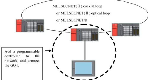
(2) When the existing programmable controller has no empty slot
Add a programmable controller to the network. Add a communication module (for other than the MELSECNET(Ⅱ), MELSECNET/B, and MELSECNET/10 network systems) to the new programmable controller, and change the connection type between the programmable controller and the GOT.
Example of accessing the network by adding a programmable controller to the network
MELSECNET(Ⅱ) coaxial loop
or MELSECNET(Ⅱ) optical loop
or MELSECNET/B
Add a programmable controller to the network, and connect the GOT.
[Issue No.]
GOT-A-0009-J
[Page]
26/42
[Title]
Precautions when Replacing GOT-A900 Series with GOT1000 Series
[Date of Issue]
Ver. J: May 2015 (First Edition: September 2005)
[Relevant Models]
GOT-A900 Series
TECHNICAL BULLETIN
5.5 Replacing the GOT-A900 series connected to the MELSECNET/10 (programmable controller to programmable controller optical loop/coaxial bus) network system with the GOT1000 series
Use the MELSECNET/H communication unit listed in Section 4.4.1, set the MELSECNET/H communication unit to the MELSECNET/10 mode, and connect the GOT to the MELSECNET/10 network system.
MELSECNET/10
GOT-A900 MELSECNET/10 communication unit
MELSECNE T/H MELSECNE T/10
GOT1000
MELSECNET/H communication unit (Connect with MELSECNET/10
5.6 When using the RUN/OUTPUT terminal of the GOT-A900 series power supply
The GOT1000 series power supply does not have the RUN/OUTPUT terminal.
When you use the RUN/OUTPUT terminal of the GOT-A900 series, consider using the RUN output of the external I/O unit (GT15-DIO).
For the details of the external I/O unit, refer to the following.
- GT15 External I/O Unit (Positive Common Input/Sink Type Output) User's Manual (IB-0800382) (GT15-DIO) - GT15 External I/O Unit (Negative Common Input/Source Type Output) User's Manual (IB-0800425)
[Issue No.]
GOT-A-0009-J
[Page]
27/42
[Title]
Precautions when Replacing GOT-A900 Series with GOT1000 Series
[Date of Issue]
Ver. J: May 2015 (First Edition: September 2005)
[Relevant Models]
GOT-A900 Series
TECHNICAL BULLETIN
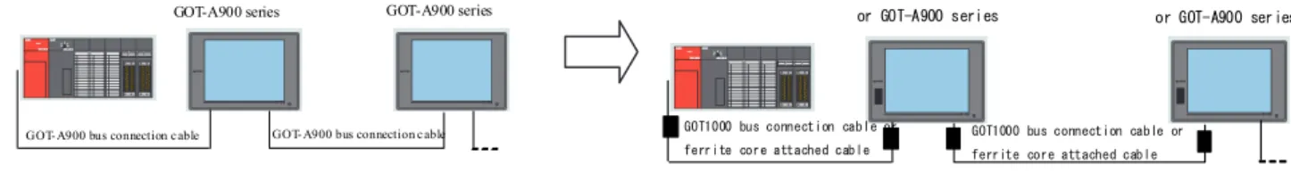
6. Cables
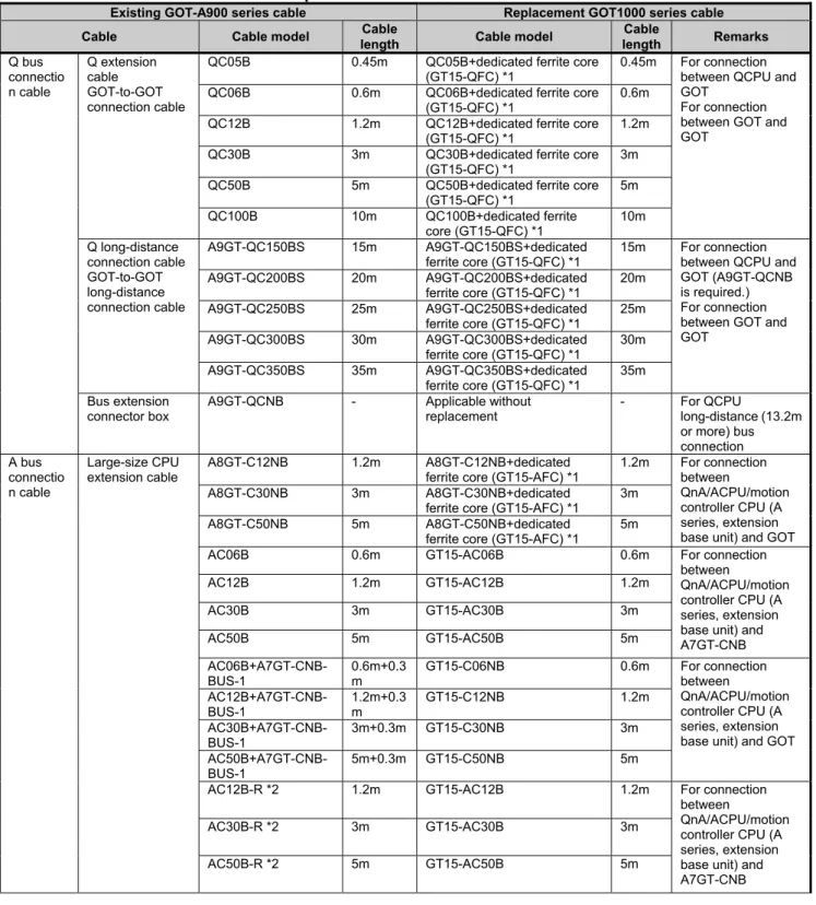
6.1 Bus connection cables
The following shows the list for replacing the existing GOT-A900 series cables with the GOT1000 series cables.
Table 6-1 Replacement cables of the GOT1000 series
Existing GOT-A900 series cable Replacement GOT1000 series cable
Cable Cable model Cable
length Cable model
Cable
length Remarks
Q bus connectio n cable Q extension cable GOT-to-GOT connection cable
QC05B 0.45m QC05B+dedicated ferrite core (GT15-QFC) *1
0.45m For connection between QCPU and GOT
For connection between GOT and GOT
QC06B 0.6m QC06B+dedicated ferrite core (GT15-QFC) *1
0.6m QC12B 1.2m QC12B+dedicated ferrite core
(GT15-QFC) *1
1.2m QC30B 3m QC30B+dedicated ferrite core
(GT15-QFC) *1
3m QC50B 5m QC50B+dedicated ferrite core
(GT15-QFC) *1
5m
QC100B 10m QC100B+dedicated ferrite
core (GT15-QFC) *1
10m Q long-distance connection cable GOT-to-GOT long-distance connection cable
A9GT-QC150BS 15m A9GT-QC150BS+dedicated ferrite core (GT15-QFC) *1
15m For connection between QCPU and GOT (A9GT-QCNB is required.) For connection between GOT and GOT
A9GT-QC200BS 20m A9GT-QC200BS+dedicated ferrite core (GT15-QFC) *1
20m A9GT-QC250BS 25m A9GT-QC250BS+dedicated
ferrite core (GT15-QFC) *1
25m A9GT-QC300BS 30m A9GT-QC300BS+dedicated
ferrite core (GT15-QFC) *1
30m A9GT-QC350BS 35m A9GT-QC350BS+dedicated
ferrite core (GT15-QFC) *1
35m Bus extension
connector box
A9GT-QCNB - Applicable without
replacement
- For QCPU
long-distance (13.2m or more) bus connection A bus connectio n cable Large-size CPU extension cable
A8GT-C12NB 1.2m A8GT-C12NB+dedicated
ferrite core (GT15-AFC) *1
1.2m For connection between
QnA/ACPU/motion controller CPU (A series, extension base unit) and GOT
A8GT-C30NB 3m A8GT-C30NB+dedicated
ferrite core (GT15-AFC) *1
3m
A8GT-C50NB 5m A8GT-C50NB+dedicated
ferrite core (GT15-AFC) *1
5m
AC06B 0.6m GT15-AC06B 0.6m For connection
between
QnA/ACPU/motion controller CPU (A series, extension base unit) and A7GT-CNB
AC12B 1.2m GT15-AC12B 1.2m
AC30B 3m GT15-AC30B 3m
AC50B 5m GT15-AC50B 5m
AC06B+A7GT-CNB-BUS-1
0.6m+0.3 m
GT15-C06NB 0.6m For connection
between
QnA/ACPU/motion controller CPU (A series, extension base unit) and GOT AC12B+A7GT-CNB-BUS-1 1.2m+0.3 m GT15-C12NB 1.2m AC30B+A7GT-CNB-BUS-1
3m+0.3m GT15-C30NB 3m
AC50B+A7GT-CNB-BUS-1
5m+0.3m GT15-C50NB 5m
AC12B-R *2 1.2m GT15-AC12B 1.2m For connection
between
QnA/ACPU/motion controller CPU (A series, extension base unit) and A7GT-CNB
AC30B-R *2 3m GT15-AC30B 3m