A study of pellet-plasma interactions using fast
three-dimensional imaging in
Large Helical Device
Jyoti Shankar Mishra
DOCTOR OF
PHILOSOPHY
Department of Fusion Science
School of Physical Sciences
The Graduate University for Advance Studies
2011 (School Year)
Dedicated to my parents
– Louis Pasteur
Acknowledgements
Three years of study at National Institute for fusion Science (NIFS) passed like a speeding Shinkansen. Sakura blossomed with time, and will be in the next spring, but I will miss it; it will be a pleasant memory forever. Time to wrap-up my thesis on pellet fueling studies in the Large Helical Device (LHD). I take this opportunity to thank the peoples helped me during this course of work.
At first, my deep sense of gratitude and appreciation to my thesis supervisor Dr. Ryuichi Sakamoto for giving me an opportunity to undertake this PhD project. I sincerely thank him for his continuous encouragement and endless support. Whenever I get puzzled, he comes up with a viable solution. Not only plasma physics but also I learn other aspect of the experimental work from him. I am deeply thankful to him and his family for their help towards my family during my stay in Japan
I would also like to thank Prof. Hiroshi Yamada for his continuous encouragement and sug- gestions on my work, especially, during any presentations. Sincere thank to Dr. G. Motojima and Dr. A. Matsuyama for their cooperation during my work in NIFS. It’s my pleasure to acknowledge fellow graduate student and my tutor Mr. A. Murakami for helping me, whenever I need.
My sincere thank to Prof. S Morita for the interesting conversations on diverged topics in leisure time. Special thank to Prof. B. Peterson for helping in English correction of my papers. I would like to thank peoples of the engineering group for helping me in the pellet injector instal- lation. It is pleasure to acknowledge Prof. S. Okamura, Prof. S. Sudo, Prof. M. Skoric, Dr. J. Miyazawa, Dr. T. Morisaki, Dr. S. Masuzaki, Dr. M. Goto, Dr. M. Kobayashi, Dr. N. Yanagi, Dr. K. Tsumori. I would also like to thank all my fellow graduate students.
I wish to express my appreciation to all the members of the LHD experimental group, NIFS, and the administrative staffs for their support. My sincere gratitude to previous and present Di- rector General of NIFS Prof. Osamu Motojima and Prof. Akio Komori, respectively for their encouragement.
Back-home in India, I am grateful to Prof. P. K. Kaw, Director, Institute for Plasma Research (IPR), Gandhinagar, for his continuous interest, and to the members of the academic committee for granting me leave to pursue my higher study. I wish to convey my regards to my boss Ms. R.
professional work in SXR diagnostics group. Thanks to all my friends in India, for their continuos encouragement for my PhD.
I would like to thank all the Japanese friends for their continuous support towards my social life in Japan. Special thank to Mr. Yutaka and his wife Ms. Noy for their endless help. I would also like to thank Ms. Sachie, Ms. Misuzu and their family, and Ms. Mieko for their continuous help on various social matters.
Many many thanks to our beloved bhaina (Mr. CRC Mohanty) and bhauja (Ms. S. Mohanty), for those joyful moments we share in many occasions. Thanks to my all cricketer friends for those cricketing times, which boost my energy from time to time.
I am indebted to my wife Jini for her inexhaustible love and inspirations, and especially, during the moments I face difficulty in my work. The joyful moments I share with my cute son Shashwat is simply inexpressible.
I wish to thank my in-laws and family members, for their continuous encouragement during my PhD. Finally, I am grateful to my parents for their endless love, support and encouragement towards my research work. To them, I dedicate my thesis.
List of Publications
[1] “A low speed single barrel pellet injector and its application to complementary study on ablatant in LHD”,
J. S. Mishra, R. Sakamoto, G. Motojima, H. Yamada, J. Plasma Fusion Res. SERIES, Vol. 9 (2010).
[2] “Design and performance of a punch mechanism based pellet injector for alternative injection in the large helical device ”,
J. S. Mishra, R. Sakamoto, G. Motojima, A. Matsuyama, H. Yamada, Review. of Scientific Instruments, 82, 023505 (2011).
[3] “Observation of three-dimensional motion of pellet ablatant in LHD”, J. S. Mishra, R. Sakamoto, G. Motojima, A. Matsuyama, H. Yamada, Proceedings of 37th EPS Conference on Plasma Physics, P5.170.
[4] “Observation of three-dimensional motion of the pellet ablatant in the Large Helical Device”, J. S. Mishra, R. Sakamoto, A. Matsuyama, G. Motojima, H. Yamada,
Nucl. Fusion 51 (2011) 083039.
Abstract
This study is focused on to address the pellet fueling issues such as ablation and mass redis- tribution in the large helical device (LHD). It has been found that the ablation dynamics strongly regulated by the local fast ion density profile generated due to the neutral beam injection (NBI) heating. Owing to the asymmetric ablation in presence of the fast ions, three dimensionality in the pellet trajectory, and subsequently change in the fueling characteristics has been observed. To explore the improved fueling properties by considering the ∇B structure of the injection location on the pellet ablatant, pellet injection studies are performed for the high field side, and the low field side injection locations. A comparative study of fueling efficiency is presented at different plasma conditions for these locations.
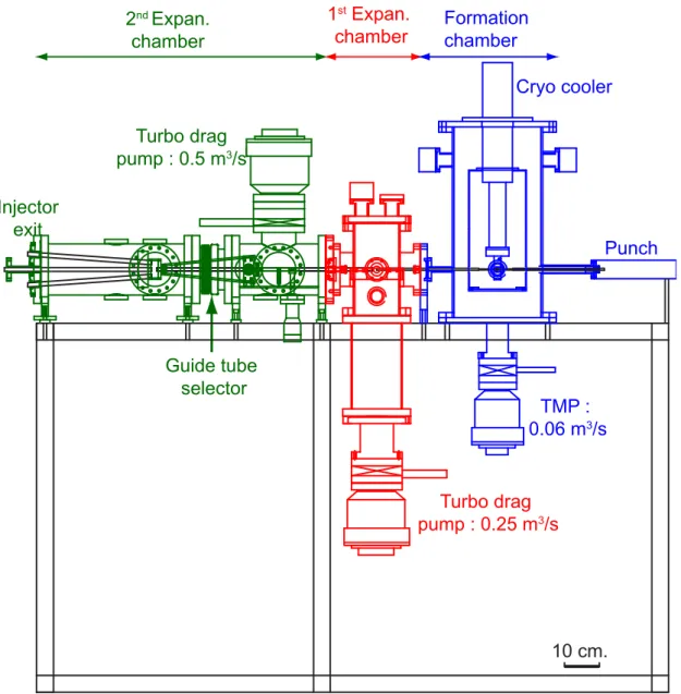
To deliver an intact pellet within the curved guiding path for an injection location other than outboard side, a low speed pellet injector is developed. This injector works on the combined operation of a mechanical punch and He propellant gas. This injector can inject a 3 mmϕ × 3 mmℓ intact pellet with speed ≤ 275 ms−1 at a pellet formation temperature of 8.0 K, flexibly. The loss in pellet speed and mass inside the guide tube are less than 6% and 10%, respectively.
Since, pellets are injected into the plasmas of 3D magnetic configuration, a three-dimensional pellet-plasma interaction can be predicted. Therefore, applying the stereoscopic technique, a 3D diagnostics system has been calibrated to image the pellet ablation process inside the plasma. This imaging system uses a fast camera (time resolution ofµs scale) and bifurcated coherent imaging fiber. The calibration error of this system is < ± 20 mm in the pellet penetration direction and within±5 mm in the transverse direction, and is able to measure the ablation dynamics with good accuracy.
In presence of asymmetric tangential NBI heated plasmas in LHD, an ablating pellet deflects in toroidal and vertical direction rather than continuing its 1D motion along its injection direction. Whereas, a both sided NBI has less significant effect on the pellet deflection. The toroidal deflec- tion is≤ 20 cm with acceleration of the order of 106ms−2. The toroidal deflection is successfully explained due to the unilateral ablation by the fast ions on the pellet surface and the formation of the rocket force in passing fast ions direction. At higher ne, reduction in deflection speed indicates the reduction of fast ion effect. In addition, the role of rotational transform on the pellet ablation
breaks the general assumption of the penetration depth, considering the constant pellet speed. In case of the LFS injected pellet, similar to that of the tokomak results, an outward redis- tribution of the pellet mass has been observed in LHD. In tokomaks, owing to the ∇B induced redistribution of the pellet ablatant, a better fueling efficiency has been reported for HFS pellet injection. As the ideal HFS resides under the helical coil in LHD, it is difficult to access this lo- cation. Therefore, in an alternative approach, injection of a pellet from the vessel inboard side with an oblique angle to a location closed to the helical coil has been considered. The injection position is optimized by performing a simple calculation for E× B drift effect on the plasmoid for that location. In alternative injection case, due to the fast ion effect, the pellet deflects three dimensionally to a location having similar characteristic as that of the LFS injection. Therefore, final mass deposition profile seems to be similar as that of the LFS injection case. The difference in pellet penetration and the deposition peak is around 15 - 20 cm. This indicates the outward redis- tribution of pellet mass. This behavior is also confirmed by analyzing the pellet ablation images, where outward mass drift at a speed of 8-10 kms−1 or more has been recorded. Considering the E× B drift effect for the alternative injection, it has been found that there are certain possibilities for enhanced deposition, if the pellet can be able to approach the calculated HFS location.
This work leads to the conclusion that the fast ions play a significant role in the pellet ablation process. While discussing the fueling process in the fusion reactor, the effect of the energetic ions on the pellet penetration process should be taken into account. Considering the similarity in redistribution phenomenon of the pellet ablatant in LHD and tokomak for LFS injection, it can be said that, the HFS fueling is necessary for reactor grade plasmas.
Contents
Table of Contents xi
List of Figures xii
List of Tables xvi
1 Introduction 1
1.1 World energy crises . . . 1
1.2 Nuclear fusion and plasma physics . . . 2
1.3 Plasma fueling and pellet injection . . . 3
1.4 Pellet injection and relevant diagnostics in LHD. . . 5
1.5 Objective of this thesis . . . 10
1.6 Outline of thesis . . . 11
2 Pellet fueling scenarios in helical system 13 2.1 Introduction . . . 13
2.2 Pellet ablation . . . 14
2.3 Mass homogenization . . . 15
2.4 LHD and ∇B structure . . . 19
2.5 Injection position optimization . . . 21
2.6 Summary . . . 25
3 Development and characterizations of a low-speed pellet injector 27 3.1 Introduction . . . 27
3.2 Design Criteria . . . 28
3.3 Design of the pellet injector . . . 29
3.3.1 Properties of Hydrogen isotopes . . . 29
3.3.2 Cryogenic Chamber . . . 32
3.3.3 Vacuum and gas feed system . . . 33
3.3.4 Diagnostics . . . 37
3.3.5 Control and Data acquisition . . . 38
3.4 Injector Operation and Characterization . . . 41
3.4.1 Pellet formation and launching . . . 41
3.4.2 Pellet speed and Ideal gun theory . . . 42
3.4.3 Characterization of the pellet injector . . . 44
3.5 Summary . . . 50
4 Stereoscopic Diagnostics 51 4.1 Introduction . . . 51
4.2 Stereoscopic principle . . . 52
4.3 Pixel correspondence . . . 55
4.4 Instrumentation and Camera Calibration . . . 56
4.4.1 Instrumentation . . . 57
4.4.2 Camera Calibration . . . 58
4.4.3 Application to pellet ablation study . . . 62
4.5 Summary . . . 64
5 Stereoscopic observation of the pellet ablatant in LHD 65 5.1 Introduction . . . 65
5.2 Experimental setup . . . 67
5.3 Experimental Results . . . 70
5.4 Discussions . . . 84
5.4.1 NBI Heating and Fast ion in LHD . . . 84
5.4.2 Rocket Effect and Pellet Toroidal Deflection . . . 87
5.4.3 Field Geometry and Pellet Vertical deflection . . . 91
5.5 Summary . . . 92
6 Pellet injection studies from multiple injection locations 95 6.1 Introduction . . . 95
6.2 Experimental setup . . . 97
6.3 Results and Discussion . . . 99
6.3.1 Low field side pellet injection . . . 100
6.3.2 Inboard high field side pellet injection . . . 106
6.3.3 Plasmoid drift and mass redistribution . . . 114
6.3.4 Pellet fueling efficiency . . . 119
6.4 Summary . . . 121
7 Summary and Conclusion 123
Bibliography 126
List of Figures
1.1 Reactivity for the D-T, D-D and D-He3. . . 3
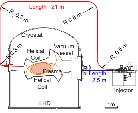
1.2 Cross section of LHD showing horizontal and vertical elongated section. Various coils position, vacuum vessel, and cryostat are also shown. . . 6
2.1 Schematic of the NGS pellet ablation model . . . 14
2.2 Plasmoid drift mechanism in presence of non-uniform magnetic field. . . 16
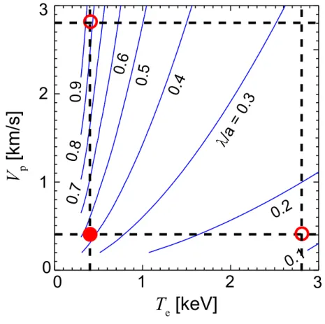
2.3 Contour plot of the pellet penetration as a function of the Teand Vp. . . 18
2.4 Poloidal section of LHD showing, (a) Horizontally elongated, (b) Vertically elon- gated section. A HFS exist under the helical coil, ∇B has four different directions. . 19
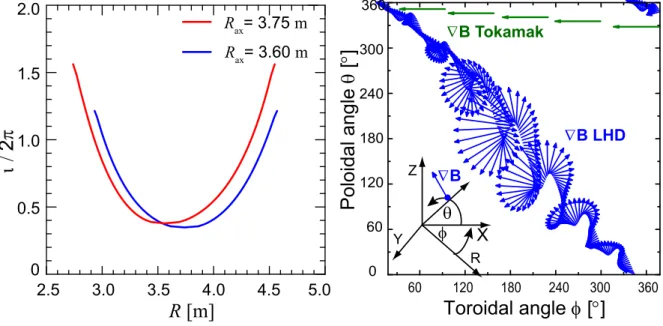
2.5 (a) Rotational transform of the LHD B field. (b) ∇B structure on the field line throughout the torus indicating the three-dimensionality of the LHD plasma. . . . 20
2.6 Three dimensional view of the E× B vector direction on the pellet plasmoid for a horizontally elongated outboard section injected pellet (bottom). Projections of the above vector on poloidal plane (Top). Color bar indicates the drift direction within 60 cm expansion of the plasmoid along the toroidal direction. . . 22
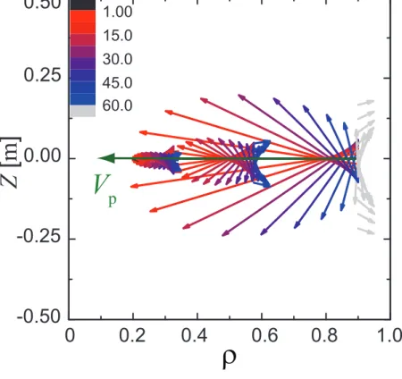
2.7 Projection of E× B drift direction for vertically elongated inboard injection. . . 23
2.8 (a) Cross section of the alternative injection location: oblique angle injection close to helical coil. (b) Projected E× B drift direction for this location. . . 24
3.1 Schematic view of the punch-mechanism based low speed pellet injector . . . 30
3.2 Phase diagram of H2isotope showing solid, liquid and gas phases. Triple point at a temperature of 13.9 K is indicated by the solid diamond symbol. . . 31
3.3 Vacuum system of pellet injector showing pellet formation region, two stage dif- ferential pumping system and gas (fueling and propellant) feed system. . . 34
3.4 Vacuum characteristics curve for two-stage differential pumping system. . . 35
3.5 Schematic view of LHD with guide tubes connecting between the pellet injector and various injection ports. . . 37
3.6 Photo diode signal for both light gates used for the calculation of pellet speed . . . 38
3.7 Block diagrams of the injector control and data acquisition system . . . 39
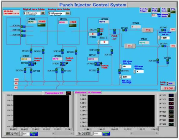
3.8 LABVIEW based user interface control for the injector remote operation. . . 40
3.9 Low speed pellet injection mechanism using mechanical punch and pneumatic pro- pellant system. . . 41
3.10 IGT approximation of pellet speed at different propellant pressure (Solid line). The dashed curve indicates the IGT speed after pressure, P0, and barrel length, L0, correction. Solid circles indicating the experimentally observed pellet speed. . . . 44 3.11 Shadow-graphic image of (a) an intact pellet at 348 ms−1and (b) a broken pellet at
380 ms−1 taken at inboard side guide tube exit. The circles on both figure indicate the position of pellet / pellet fragments on the image. . . 45 3.12 Change of pellet speed with propellant pressure at different Tp. . . 46 3.13 Comparison of Vp at curved guide tube exit with pellet muzzle speed (filled sym-
bols) at different Tp. Pellet speed reduction (%) with muzzle speed (open symbol) . 47 3.14 Intact pellet fraction plotted against injection speed at different Tp. The horizontal
bars indicate the bin size of the speed taken to estimate the intact pellet fraction. . . 48 3.15 Comparison of experimentally obtained intact speed (Solid circle) with calculated
intact speed (Broken line) at different Tp . . . 49 4.1 Schematic of stereoscopic measurement principle. . . 54 4.2 Stereoscopic diagnostic setup with fast camera and bundled fiber. . . 57 4.3 Camera calibration setup. The coordinates X , Y and Z represent the plasma ver-
tical, toroidal, and the pellet injection direction of the plasma, respectively. The epipolar plane corresponding to a world coordinate is also indicated. . . 58 4.4 Epipolar lines (in right half image) corresponding to a number of points in the left
image shows the closeness of the estimated points to the actual points. . . 61 4.5 (a) Stereo reconstructed error along Z direction (Maximum error ±18 mm). (b)
Error in in X−Y direction for all Z-positions. An error of 10 mm is indicated by the bounding circles of 10 mm radius. . . 62 4.6 A typical picture of an ablating pellet image taken from two different locations.
The epipolar line corresponding to the pellet position in left image is shown on right image . . . 63 4.7 Time evolution of the stereo reconstructed pellet position and Hα ablation intensity.
Predicted pellet position by considering the constant pellet speed is indicated by the solid line. The open circles show the stereo reconstructed pellet penetration speed. . . 63 5.1 (a) Three dimensional view of the LHD plasma with helical coils, (b) Mid-plane
top view of pellet injection showing plasma flux surface, pellet injection direction and stereoscopic observation system. (c) Vertical view of injection cross section. Field of view of the camera lenses is shown by the hatched region. . . 68 5.2 Temporal evolution of a typical pellet injected discharge (# 60825: CW-NBI and #
59515: CCW NBI). Shaded region corresponds to the pellet timing considered in this study. . . 71 5.3 Hα and camera intensity signal for CW and CCW NBI case. The last closed flux
surface (LCFS) and pellet ablation time are indicated by dashed line in both figure. 72 5.4 Loss function L(E) and effective cross-section Λ(E) of electrons and ions . . . 73
LIST OF FIGURES
5.5 (a) & (b) Projection of the magnetic flux surface on the camera image showing elongation of the pellet cloud along the magnetic field lines (solid lines). (b) Change in plasmoid angle with the plasma mid-plane while penetrating into the plasma. (c) Comparison of the pitch of the magnetic field line and the plasmoid angle with the plasma mid-plane, along R. . . 75 5.6 (Top) Reconstructed pellet trajectory on (a) toroidal (mid-plane view) and (b) ver-
tical plane of the LHD for CW-NBI injection. Shaded area indicates the viewing area of the observation system. Direction of the pellet injection and tangential NBI are indicated by the arrows. (Bottom) The pellet trajectory on (c) toroidal (mid-plane view) and (d) vertical plane, in the case of the CCW-NBI injection. . . 77 5.7 Reconstructed pellet trajectory on (a) toroidal (mid-plane view) and (b) vertical
plane of the LHD for CCW-NBI injection. . . 78 5.8 Histogram (20 pellets for each case) showing the variation of the deflection ra-
dius in presence of CW and CCW NBI conditions. Deflection radii of the two discharges analyzed in this study are indicated by the arrows. . . 79 5.9 Pellet speed along vertical (Vpol), toroidal (Vtor) and negative major radial (Vrad)
direction of the plasma for (a) CW and (b) CCW NBI injection.(c) Pellet toroidal acceleration in both NBI conditions, negative acceleration means CW direction. . 80 5.10 Variation of maximum toroidal deflection speed with fast ion collision time. . . 81 5.11 Time evolution of the pellet penetration in plasma under two NBI conditions. . . . 82 5.12 Radial profiles of Te and ne before and after the pellet injection in the case of
CCW NBI plasma. Observed penetration depth is indicated by the vertical dashed line. The difference in two density profiles (∆ne) shows the effective pellet mass deposition. . . 83 5.13 Pellet ablation profile calculated by using ABLATE code signifies the effect of fast
ion on the pellet ablation process. . . 85 5.14 Formation of a rocket effect due to assymmetric ablation by the fast ions. . . 86 5.15 Calculated fast ion density profiles along the pellet trajectory. Shaded area corre-
sponds to the bending radius in the cases of CW and CCW NBI conditions. . . 90 5.16 Comparison of the observed vertical deflection (filled symbols) and poloidal shift
(absolute value) of the field lines, calculated from the field line tracing (dashed lines) within the pellet life time at different pellet deflection radii. . . 93 6.1 Schematic of the pellet injection cross-section for LFS and HFS injection showing,
(a) top view of mid-plane and (b) vertical view. Origin of the pellet position (Xpol, Ytor, Zrad) inside the vessel is taken at the Lens-2 camera port. The shaded portions (in top figure) represent the viewing area of each camera. . . 98 6.2 The range of the plasma parameters covered in this experiment. The size of a
symbol represents the pellet injection speed in the corresponding speed range. . . . 100 6.3 Waveform of a typical pellet injected discharge for LFS injection showing: (a) Hα
ablation light, (b) central electron temperature Te0, (c) plasma stored energy and the port through NBI power, and (d) line averaged electron density ¯ne. . . 101
6.4 Experimental penetration depth plotted against the predicted penetration depth considering the NGS model (electron ablation only). . . 102 6.5 Temperature dependence of the penetration depth in the density range (1-2)×1019
m−3in case of low speed and high speed pellets. The solid line indicates the Te−0.68 fitting of the data’s. . . 104 6.6 Radial profiles of the Teand neobtained from the Thomson scattering diagnostic in
the case of (left) low speed (# 104254), and (right) high speed (# 99391) injected pellets. The particle deposition profile, which is the difference in density profile after and before the pellet injection, is shown by the inverted solid triangles. Hα ablation light indicating the pellet penetration depth is also shown. . . 105 6.7 Waveform of a typical pellet injected discharge for alternative injection showing
(a) Hα ablation light, (b) central electron temperature Te0, (c) Plasma stored energy and the port through NBI power, (d) line averaged electron density ¯ne. . . 107 6.8 Reconstructed pellet trajectory for alternative location injected pellet on (a) verti-
cal plane (φ = 23◦ section) and (b) toroidal mid-plane of LHD. The shaded area indicates the viewing area of the observation system. (c) Pellet speed in three di- rections, injection speed and the total speed of the pellet. . . 108 6.9 Pellet toroidal deflections as a function of the fast ion density ratio. . . 110 6.10 Maximum toroidal deflection as a function of the ion collision time for the inboard
(open diamond) and outboard injection (solid diamonds). . . 111 6.11 Radial profiles of the Teand neobtained from the Thomson scattering diagnostic in
the case of (left) less CW deflected pellet (# 104237), and (right) CCW deflected pellet (# 102885). The particle deposition profile, which is the difference in the density profile after and before the pellet injection, is shown by the inverted solid triangles. Hα ablation light indicating the pellet penetration depth is also shown. . . 113 6.12 Typical fast camera view of an ablating pellet from two different observation points
for, (top) outboard LFS and (bottom) inboard HFS. . . 115 6.13 Typical fast camera image sequence (single view) of an ablating pellet in both type
of injection, showing break-away plasmoids drifting in a direction opposite to that of the pellet injection direction . . . 116 6.14 Temporal evolution of the pellet ablation light and the line averaged density for the
chords at the boundary ( ¯nbe) and core plasma ( ¯nce) . . . 118 6.15 (a) Pellet fueling efficiency as a function of the penetration depth. (b) Degradation
of theεf with the increase in NBI power. . . 119
List of Tables
1.1 List of LHD diagnostics . . . 8 3.1 Properties of H2isotopes . . . 31
Chapter 1
Introduction
1.1 World energy crises
Energy is the vital need for human civilization. The increase in world population impetus the energy demands. At least 50 % increase in demand is expected by the middle of this century, mainly due to the increase in population [1]. Furthermore, according to the Unite Nations, still 1.5 billion peoples in developing countries having no access to the electricity [2]. At present 80 to 90 percent of total worldwide energy is derived from the combustion of the fossil fuels [3]. As the reserves are limited, it is expected that this will last for few hundred years (Oil and gas within the next 50 years and coal within 300 years) [4]. In addition, burning of fossil fuels has adverse impact on the climate change. There are many alternatives to fossil fuels such as biomass, wind power, and solar power etc. However, the large-scale productions of these are limited. Therefore, energy from the nuclear power is a viable solution for future energy crises. Nuclear fission and nuclear fusion are the two forms of the nuclear energy. In the case of the nuclear fission, there are hazards of radiation, and also high risk of the nuclear waste management as these are radioactive in nature with longer half-life period. Nuclear fusion is safer than the nuclear fission, as the nuclear waste from fusion machines will be very less with limited long-term waste disposal requirements. It is also a clean source of energy with almost no environmental impact.
1.2 Nuclear fusion and plasma physics
Nuclear fusion is the process of combining two light nuclei to form a heavier nucleus. During this process the mass difference of the reaction is converted into energy according to the Einstein’s relation, E=mc2. In order to induce the fusion of nuclei, it is necessary to overcome the coloumbic repulsion between like charged particles by applying higher energy. Therefore the most promising method of supplying the energy is to heat the reactant to millions of degree Celsius. At this tem- perature the reactants are fully ionized. The electrostatic charge of the nuclear ions is neutralized by the presence of equal number of electrons, which exhibit a collective behavior and the result- ing nuclear gas is called the plasma. To achieve the high temperature needed for nuclear fusion, plasma must be confined so that it does not lose energy and cool. There are numerous mechanisms for plasma confinement, including gravitational (in stars), inertial, and magnetic confinements. However, magnetic confinement is the most favorable, and advanced solution for laboratory scale plasmas to produce thermonuclear fusion in steady state conditions. The leading fusion machines in the field of magnetic confinement are stellarator and tokamak.
The most promising fusion reaction in magnetic confinement is that in which the nuclei of deuterium and tritium fuse to produce anα-particle of energy 3.5 MeV and a neutron of 14.1 MeV. The reactivity cross-section for various fusion reactions is shown in Fig. 1.1. As the reactivity cross-section for D-T reaction is maximum just over 100 keV, this reaction is favorable over other two reactions [5]. The condition necessary to initiate the fusion reaction is defined by the Lawson criteria, which is written as,
nτεTe> 3 × 10²¹m−3s keV. (1.1) where, n is the ion density,τε in the energy confinement time and Teis the electron temperature of the plasma. Therefore, the plasma density and the temperature are important factors for achieving the nuclear fusion.
1.3 Plasma fueling and pellet injection
1 101 102 103
10-25 10-24 10-23 10-22 10-21
D-He3 D-T
D-D
10-26
συ [m
3s
-1]
T
e[keV]
Figure 1.1 Reactivity for the D-T, D-D and D-He3.
1.3 Plasma fueling and pellet injection
The plasma is formed by ionization of pre-filled gas. After the plasma is formed, it is necessary to maintain the discharge by replenishing the spent fuel. There are several possibilities of refueling the plasma such as gas puff, NBI injection and pellet injection. Although gas puffing is the simplest way of plasma fueling, major concern for this is the low fueling efficiency. The fueling efficiency for the gas puff is less than 20 % in the case of tokamaks using active diverter [6] and the condition worsens for reactor grade machines. Core fueling is necessary for the next generation plasma devices like ITER [7]. Therefore fueling by gas puff is not capable of high-density operation. Besides heating of the plasma, neutral beam can also be used for plasma fueling. However for bigger scale fueling, the particle should be accelerated to very high energies and currents (1 MeV,
40 A), which create technological challenge [8].
In comparison to the above two methods, frozen pellets of the isotopes of Hydrogen at liquid He temperature with speed few hundreds to thousands of ms−1 has become the most favorable method for refueling magnetically confined plasmas. The major advantage of this method is the core fueling and peaking of the plasma density profile accomplished by deep penetrated pellets. In addition, power required by this method to inject the fresh fuel is negligible in comparison to the fueling by the neutral beam injection. Using the pellet injection, improved particle and en- ergy confinement properties have been demonstrated by several confinement devices including, Alcator-C [9], DIII-D [10], TFTR [11], ASDEX [12], JET [13], JT-60 [14, 15] and LHD [16]. Enhancement of the plasma performance depends upon the pellet penetration and subsequent de- position of the ablated mass inside it. Concerning with the pellet ablation in the plasma, several models have been proposed on the basis of the neutral gas shielding (NGS) [17] on the ablation characteristics. The advancement of the NGS model considering the additional shielding from the low temperature plasma cloud surrounds the pellet has also been formulated in the form of the neutral gas and plasma shielding (NGPS) model [43]. In the framework of the NGS model, the normalized penetration depth (λ /a) inside the plasma that depends upon the plasma electron density (ne) and temperature (Te), and the pellet radius (rp) and speed (Vp), is given by [107],
λ
a = 0.079T
e−5/9n−1/9e rp5/9Vp1/3 (1.2)
Due to strong dependence of the electron temperature on the pellet penetration, it will be great challenge to fuel the fusion grade plasmas, even if the pellet injection speed can be increased to the possible technological limits.
A discrepancy between the pellet penetration and effective mass deposition depth is reported in tokamaks. This indicates the existence of a redistribution process of the pellet mass, just after the ablation. This redistribution is believed to be due to a drift force down the magnetic field gradient, towards the low field side (LFS) of torus. In tokamaks, this drift expels the deposited matter out of the plasma in the case of LFS pellet injection, while it favors core deposition for the
1.4 Pellet injection and relevant diagnostics in LHD.
high field side (HFS) injection [102]. With increase in heating power, degradation of the fueling efficiency, observed in case of LFS injection has not been found in HFS fueling. Therefore, it now seems less critical to dispose of high-velocity pellet injectors to fuel a reactor scale device. This enhanced mass deposition profile encourages to use the HFS fueling in ITER [18]. Considering this redistribution process, recent pellet ablation models are aims to predict the exact mass deposition profile inside the plasma with the inclusion of mass drift effect [19]. Apart from use of the pellet for plasma fueling, analysis of pellet trajectory is also used as a diagnostic tool to get the information about the particle transport [20] and q-profile measurement [21]. Recently, small sized Hydrogen pellets are also used to control the ELM frequency in ASDEX-U [22]. Apart from the pellet ablation physics, significant progress has been made in the areas of the pellet injector technology. A detail of the various injection technologies can be found in [62].
1.4 Pellet injection and relevant diagnostics in LHD.
Large Helical Device (LHD), Worlds largest heliotron type plasma device is built with an objective to demonstrate the steady state plasma operation [23]. One of the advantage of this device over tokamak is the current-less, and disruption free plasma. The major radius varies between 3.5≤ R
≤ 4.0 m for different operational conditions. The largest plasma volume is 30 m3for the standard configuration of R = 3.6 m. The averaged minor radius is 0.6 m. The magnetic field strength on the plasma axis is up to 3 T. A cross sectional view of LHD is shown in Fig. 1.2. In LHD, magnetic confinement field is generated by l/m = 2/10 continuous helical coils and three set of poloidal coils, where l and m are the toroidal and poloidal pitch numbers, respectively. As the confinement field is generated by external helical coils, the plasma varies elliptically between vertically and horizontally elongated sections. This helical field makes the LHD plasma three-dimensional. The poloidal coil system include sets of; (1) inner vertical (IV), (2) inner shaping (IS), and (3) outer vertical (OV) coils. All the coils are made up of superconductor. Ten pairs of local island diverter (LID) coils are placed at the top and bottom port of the vertically elongated section for edge plasma
Rax= 3.9 m
Helical Coil OV
IS
Base structure
IV
Cryogenic support
Plasma vacuum vessel
Cryostat Supporting
shell Outer
port
Inner port
5.5 m
Upper port
LHD
Figure 1.2 Cross section of LHD showing horizontal and vertical elongated section. Various coils position, vacuum vessel, and cryostat are also shown.
control [24]. The LID is a closed diverter that uses m/n =1/1 island. The position of the magnetic axis that fundamentally decides the plasma confinement is changed by the OV and IV coils. The IS coils control the ellipticity of the plasma.
A discharge can be initiated by either electron cyclotron heating (ECH) [25] and/or by neutral beam injection (NBI) [26]. The ECH used for plasma production and heating, is generated by gyrotrons at the characteristic frequency of 84, 82.6 and 168 GHz. Three negative ion based tangentially applied neutral beam injectors are the main heating devices in LHD. Out of these, two injectors are operated in Counter Clock Wise (CCW) direction and the other injector is operated in Clock Wise (CW) direction. Each NBI is designed to inject a 7.5 MW hydrogen beam at energy of 180 keV.
After the initiation of the plasma discharge, external fueling is necessary to maintain the plasma density at a specific level. LHD is equipped with gas puff [27,28] as well as pellet injection
1.4 Pellet injection and relevant diagnostics in LHD.
[65] systems for plasma fueling. Using the pellet injection, favorable dependence of the energy confinement on the plasma density has been achieved, which has not been possible by the gas puffing [16]. By using the repetitive pellet injection [29], high density steady state operation has also been demonstrated in LHD [30]. Since, NBI is the main source of the plasma heating in the pellet injected discharges, measurement of the fast ion profile in the plasma is necessary for the pellet ablation studies. The fast ion deposition profiles are evaluated by using the Monte Carlo simulation code, MCNBI [31]. The basic diagnostic systems needed to know the pellet characteristics are light gate system for pellet speed, shadowgraph, and microwave cavity [32] for the pellet intactness and mass measurement. Two light gate systems consist of laser and photo diodes, are installed in the injector to measure the injected pellet speed. A CCD camera with nano second pulsed light is used to capture the pellet image. The pellet shape and mass provide the information about the particle content of the injected pellet into the plasma, which further needed for the fueling efficiency estimation. The Hα and the fast imaging camera diagnostics are installed to analyze the pellet dynamics inside the plasma. The pellet ablation light is measured by a Si-PIN photo diode with a Balmer alpha, Hα filter at a time resolution of 1µs. Stereoscopic diagnostics [80] consisting of two bifurcated imaging fiber and a fast imaging camera is employed to extract the information about an ablating pellet. The image resolution of the camera is more than 100 K pixel. The images are obtained with temporal resolution of 20 µs with 5 to 20 µs exposure times. A high-speed spectroscopic diagnostic, using fast camera and five arm bundled fiber has been installed in LHD to characterize the ionized pellet ablation cloud (plasmoid) in LHD [33]. The spectra of Hydrogen Balmer-lines and background continuum radiation, depend on the electron density and temperature of the plasmoid. Therefore the Balmer-β line (wavelength: 486.1 nm) and continuum (wavelength: 576.8 nm) lines are used to evaluate the density and the temperature of the plasmoid.
While developing the diagnostic systems for LHD, capability to address the key issues such as multi dimensional measurements (because of non-axisymmetricity of the plasma) and operation
Table 1.1 List of LHD diagnostics
Diagnostics Measurements
FIR laser Interferometer Line integrated ne(r)
Co2laser Interferometer High neplasma measurement MMW Interferometer Line-averaged ne
Thomson scattering Te(r), ne(r) Electron Cyclotron Emission (ECE) Te
X- ray pulse height analysis Te, Impurities
Hard X-ray CCD camera Two dimensional Teprofile
Charge exchange spectroscopy Te(r), Plasma rotation (Vp(r),Vt(r)) Crystal spectrometer Te, Vt
UV and Visible spectrometer Impurity, n0(H), Zeff
Bolometry Prad(r)
TESPEL Particle transport
CXS Poloidal rotation speed
Heavy Ion Beam Probe (HIBP) Φp(r), Φpfluctuation
SXR CCD camera Shafranov shift
Diamond and Silicon detectors Neutral particles
Magnetic probe Ip, Wp
Langmuir probe Edge Te, ne, Φp
Visible / Infrared camera Plasma-wall interaction Diverter spectroscopy Recycling and particle influx
1.4 Pellet injection and relevant diagnostics in LHD.
in steady state conditions, are taken into consideration. Another big issue in diagnostics is the han- dling of huge amounts of data. The following physics issues while developing the diagnostics are considered for fulfilling the LHD missions; diagnostics for (a) High nτεTe plasmas and transport physics, (b) Magnetohydrodynamics (MHD) equilibrium and stability, (c) Long pulse operation and diverter function, and (d) confinement for energetic particles. A list of important diagnostic systems in LHD is tabulated in Table 1.1. A detail knowledge of the LHD diagnostic systems can be found else where [34]
The effect of pellet injection on the plasma performance is analyzed by the electron temper- ature (Te) and density (ne) of the plasma. Line integrated ne is measured by the 13 channel FIR laser interferometer [35], positioned at a vertically elongated plasma section. High time resolved datas (up-to 1µs) can be obtained from this diagnostic and it is useful for the analysis of the mass redistribution process in a pellet-injected discharge. The radial density profile can be obtained by the Abel inversion technique [36]. A CO2 laser imaging interferometer is installed on the LHD to measure the density profile, without phase jump during high density (ne > 1020 m−3) plasma operation. A two color MMW interferometer [37] is installed to measure the ne, along the cen- tral chord on horizontally elongated section. Thomson scattering diagnostic is a useful system to obtain the plasma electron density and temperature profile, locally. This diagnostic is installed on a horizontally elongated mid-plane section in LHD [38]. As this diagnostic adopts an obliquely back scattering system, it is possible to measure the whole plasma region along the major radius on the mid-plane R, under the severe port constraint of the helical configuration. It can measure datas from 200 points radially with a spatial resolution of 15- 30 mm, which depends on the radial position of laser scattering. The plasma-stored energy (Wp) is obtained by the diamagnetic loops, which in turn is used for the estimation of the energy confinement time.
1.5 Objective of this thesis
This thesis is focused on the global issues of the pellet fueling studies, such as pellet ablation and particle redistribution process in the LHD. The questions concerning the ablation dynamics are : what is the effect of the energetic ions on the pellet ablation process? How does the three- dimensionality of the plasma affect the pellet penetration characteristics? From the viewpoint of the fueling efficiency, is it possible to demonstrate the improved fueling scenarios in LHD considering the magnetic field structure of the injection location, as observed in tokamaks?
The pellet ablation process is regulated by the local plasma parameters such as density, elec- tron temperature. Due to its strong dependence, pellet penetration decreases significantly with the increase in Te. This penetration loss affects the fueling efficiency (εf). With the increase in heat- ing power, degradation of the εf has also been reported in tokamak [85]. The generation of the energetic particles due to the external heating can strongly affect the ablation dynamics. Not only it enhances the ablation but also an asymmetry can gives rise to deflection of the pellet from its initial trajectory. In LHD, neutral beam injection (NBI) is the major source of the plasma heating in the pellet injected discharges, and hence the generation of the fast ions is significant. A two dimensional deflection of the pellet trajectory in presence of the NBI has been reported earlier in LHD [91]. Since, LHD plasma has the three-dimensional characteristics, a 3D interaction between the pellet and the plasma cannot be ruled out. Therefore an extensive study of the effect of the fast ions on the pellet ablation dynamics is one of the objectives of this thesis.
Another important aspect of the pellet fueling is the effective mass deposition. The fuelling efficiency is not only affected by the pellet penetration into the plasma, but also depends upon the mass redistribution owing to the field gradient of the injection location. In concern to this, enhanced fueling efficiencies have been reported in tokamaks for HFS injection in comparison to the LFS injection [102]. Similar to that of the tokamak results, outward distribution of the pellet mass has also been found in LHD for LFS pellet injection. Due to lack of proper diagnostics, it is premature to conclude the pellet injection characteristics for the coil side injection (HFS) performed earlier
1.6 Outline of thesis
in LHD [91]. In that study, although there is no outward redistribution of the pellet mass has been reported; due to lack of the local density measurements, it has not been possible to demonstrate the fueling behavior quantitatively. Therefore a part of work in this thesis is aimed at exploring the alternative injection scenarios for better particle deposition profiles in LHD. Since the HFS resides under the helical coil, an alternative approach to access the HFS is considered. In this approach a pellet is injected from the inboard LFS location obliquely to a region, close to the helical coil.
To support the experimental objectives, a low speed pellet injector and a fast 3D imaging diagnostic system have been developed. The proposed HFS injection location is situated at the inboard side of the torus. In order to deliver an intact pellet through the bended guide tube, a low speed pellet injection system (100-400 ms−1) using a mechanical punch device is developed. To study the 3D pellet-plasma interaction, a three-dimensional diagnostic is necessary. Since the perpendicular observations are restricted by the helical coils in LHD, a three-dimensional imaging diagnostic by applying the stereoscopic principle is calibrated. This diagnostic uses a fast camera and bifurcated imaging fiber. Not only the trajectory of the pellet but also the mass deposition characteristics can be studied by analyzing the individual image frames.
1.6 Outline of thesis
After introducing the first chapter (this chapter), Chapter-2 describes about the pellet ablation dy- namics inside the plasma, and injection position optimization in LHD. In Chapter-3, development of a low speed pellet injector, and injection test of the pellet through the bended guide tube is pre- sented. Calibration of the three-dimensional measurement diagnostic basing on the stereoscopic principle is discussed in Chapter-4. In Chapter-5 three-dimensional observation of the pellet ab- lation behavior in presence of the fast ions is discussed. Then, Chapter-6 describes the results regarding the pellet fueling and mass redistribution for the different pellet injection locations in LHD. Finally, the summary and conclusions are given in the Chapter-7.
Chapter 2
Pellet fueling scenarios in helical system
2.1 Introduction
The success of a future fusion reactor implicitly depends on the efficient fueling, which is possible by the pellet injection. In several fusion machines including the tokamak and the helical device, extended operational limits have been achieved, which has not been possible by the gas puffing [10, 16]. After the pellet enters in to the plasma, change of phase from a solid material to the mass deposition lasts for few milli-second. The overall pellet dynamics during this time can be divided into two parts, such as ablation and mass homogenization. In context with this, the successful prediction of the pellet dynamics inside the plasma is necessary. Although it has been proven as a favorable candidate for fueling, outward redistribution of the deposited mass [40] for the low field side (LFS) pellet injection is a major concern. On the other hand, for the high field side (HFS) injection, enhanced fueling efficiency (εf) has been observed in tokamak [41]. The basic question arises here is, whether the success of the HFS injection in the tokamak can be extended to the helical plasmas, which is different from the former by its three dimensional helical magnetic field. In this chapter we will discuss about these issues and will extend the global understanding in this regard to explore the favorable pellet injection locations in LHD.
2.2 Pellet ablation
Soon after a pellet enters into the plasma, it is exposed to the heat flux, carried out by the plasma electrons and ions. If the electron and the ion temperatures are equal, the electron heat flux is dominated owing to the ratio of the electron and ion mass ratiop(mi/me), where mi and me are the ion and electron masses, respectively. The pellet starts to evaporate and forms a spherical neutral cloud around it. This ablation cloud shields the pellet from the incident heat flux and hence the pellet lifetime is increased. After the formation of the neutral cloud, it is further heated and ionized, and forms a high density, low temperature ionized plasma cloud, called plasmoid. The plasmoid having high pressure inside it expands along the magnetic field line until the pressure equilibrium with the background plasma. A diagram illustrating the ablation phase is shown in Fig. 2.1. In this figure Rax, Vp, Bφ and a, represent the magnetic axis, injected pellet speed,
Flux tube
B
φPlasmoid
Electron
Ion
Pellet
Neutral gas
LCFS
a
λ
V
pR
axFigure 2.1 Schematic of the NGS pellet ablation model
toroidal magnetic field and minor radius of the plasma, respectively. The pellet penetration at a particular time from the plasma edge is represented by λ . The descriptions presented here is the simplest form of the neutral gas shielding (NGS) model [17]. This model has been systematically
2.3 Mass homogenization
modified by many researchers taking into account of various aspects such as Maxwellian electron distribution and geometrical effect [42], shielding from the ionized cloud (NGPS model) [43], and considering the atomic processes [44] . In the original pellet ablation model, the heat flux due to the electrons is only considered. In the discharges with significantly higher external heating power, the ablation rate is strongly modified by the high-energy particles. Therefore the original NGS model is latter extended by Milora [45] and Nakamura [46], taking into account of the effect of fast ions on the ablation process. While considering the energetic particle ablation, it is important to consider the effect from pitch angle and the Larmor radius of the incident flux particles. The effect of the fast ions and its asymmetry surrounding the pellet, on the ablation process is discussed in latter chapters.
The efficiency of the fueling improves with the increase in pellet penetration depth. If the pellet is completely ablated inside the plasma, then, εf close to 100% is expected. However, the fueling efficiency well below this value has been found in experiments. The experimental results indicate that the particle deposition depth is lesser than the the pellet penetration depth in the case of the LFS injection. Therefore the pellet penetration is not the end of the process, and there exist some other mechanisms that cause the degradation of the fueling efficiency by removing the particles out of the plasma.
2.3 Mass homogenization
After the ionization of the neutral cloud, the spherical cloud becomes a cigar shaped plasmoid and expands along the magnetic field lines. The expansion speed of the ablatant is much lower than that of the incoming heat flux. Therefore the energy density in the ablation cloud is rapidly increased over the ambient plasma pressure, and a localized high-β plasmoid is formed [47]. The expansion of the ionized cloud continues up-to the pressure equilibrium with the background plasma. The mass homogenization process across the flux surfaces occurs in this phase. The ionized particles at this stage move across the magnetic field due to the E× B drift force in its self-consistent electric
field. There are several possibilities for the formation of these fields in the pellet cloud [48]. One of the possibilities is, the formation of the electric field due to the gradient in the toroidal magnetic field. The above said drift force affects the final mass deposition process significantly by pushing the plasmoid towards the LFS of the torus. The simplified physical picture of E× B drift model is shown in Fig. 2.2. Let us consider an isolated ionized ablation cloud in the non-uniform
Plasmoid
B
φB1/R
j
pE (t) j
∇Β+ + + +
- - - -
j
||j
AZ
R
E × B
B
2V
pj
||Figure 2.2 Plasmoid drift mechanism in presence of non-uniform magnetic field.
magnetic field, which is proportional to 1/R. The cloud is assumed to has the constant electron and ion temperature, which are much less than the ambient one. The polarization of such a cloud arises due to the ∇B drift of ions and electrons in the vertical direction. The corresponding vertical current is,
j∇B= 2p
RB. (2.1)
2.3 Mass homogenization
Where, p= nI(Te+ Ti), is the cloud pressure. When the ionized particles start to decelerate due to the particle’s gyro-motion, the drift velocity reduces and the polarization current arises. The polarization current in the vertical direction is opposite to the ∇B drift current, and is written as,
jp=nimi B2
∂ Ez
∂ t , (2.2)
where ni and mi are the local density and mass of the injected ions, and Ezis the vertical electric field due to the polarization of the cloud. However, if the polarization current exists, there should be another current system to close the circuit. Such a current system flows in the ambient plasma. If the currents in the ambient plasma are large enough to compensate the polarization current inside the cloud, the polarization inside the cloud reduces and hence Eyfield reduces. This electric field generates the E×B drift force towards LFS of the torus. Consider, there exists an isolated plasmoid at the beginning of the drift, so that the net current inside it is zero (∇· I = 0). At this condition, two opposite current balances each other. Equating the Eqns. 2.1 and 2.2, the acceleration of the cloud can be written as,
mi∂VR
∂ t =
2(Te+ Ti)
R , (2.3)
where VR= EB×B2 is a drift velocity. This drift acts down the magnetic field gradient towards the LFS of the torus. Therefore if a pellet is injected from the low field side, due to this force, the mass is drifted out of the plasma and the fueling efficiency is low. Similarly for the HFS injection, the deposited mass drifts toward the axis of the plasma, and causes high fueling efficiency. It had been reported in several machines that the observed drift is smaller than what can be deduced from the calculation of the drift velocity, and the time scale of the mass homogenization. Various possibil- ities for the drift compensation like, Alfvén wave generation and overlapping of flux tubes after the plasmoid expands half a toroidal turn along the field line, tends to compensate the polarization field and hence the drift, are proposed in the modeling studies [70].
From the NGS scaling law for the pellet penetration (Eqn. 1.2), it can be seen that there is a strong dependence of the pellet penetration on plasma electron temperature over the pellet
injection speed. Contours plot for the pellet penetration as a function of the Te and the pellet injection velocity (Vp) for LHD is shown in Fig. 2.3. The open circles in the figure represent the
0 1 2 3
1
2
3
0.2
/ a =
0 .3
0 .4
0 .5
0 .6
0 .8
0 .9
T
e[keV]
V
p[ km/ s]
0 .7
0 0.1
Figure 2.3 Contour plot of the pellet penetration as a function of the Teand Vp.
points with seven fold increase in the plasma temperature and speed of the pellet. In this calculation ne and rp are 1× 10²⁰ m−3 and 3 mm, respectively. From the figure, it can be observed that for a seven folds increase in the injection speed, pellet penetration (λ /a) just increases by 2 times. However, for a similar increase in Te,λ /a decreases more than three times. At this temperature, if the speed is increased up-to 3 kms−1, the normalized penetration is still less than 0.3. Therefore, it will be a great challenge to fuel the reactor scale plasmas with bigger volume and higher Te, within the technological limit of the pellet injection speed. In contrast, a better fueling efficiency can be achieved even with lower injection speed by using the HFS of the torus, owing to the mass
2.4 LHD and ∇B structure
drift effect discussed above. Therefore, optimization of the fueling location is necessary in order to achieve higher fueling. The above discussed E× B drift effect can be used as a tool for the optimization of the fueling location in fusion devices.
2.4 LHD and ∇B structure
In LHD, since the helical modulation is superimposed to the toroidicity, additional high field side appears under the helical coil and varies from one location to other, hence the HFS side is not always inboard to the vacuum vessel as in the case of a tokamak. Therefore, one cannot simplify the magnetic field strength distribution like B ∝ 1/R as in axis symmetric tokamak field. The shape of the plasma in LHD varies elliptically between horizontally and vertically elongated cross- sections. The magnetic field structure of the LHD showing HFS and LFS for the above cross sections, and the ∇B directions is shown in Fig. 2.4. It can be observed from the figure that in each
2.5 3.0 3.5 4.0 4.5 5.0 5.5
−1.5
−1.0
−0.5 0.0 0.5 1.0 1.5
Z [m ]
Helical coil Helical coil
Low Field Low Field
High Field
High Field
2.5 3.0 3.5 4.0 4.5 5.0 5.5
−1.5
−1.0
−0.5 0.0 0.5 1.0 1.5
Helical coil Helical coil
Low Field Low Field
High Field
High Field
R [m]
∇B
∇B
∇B
∇B
(a) (b)
R [m]
Figure 2.4 Poloidal section of LHD showing, (a) Horizontally elongated, (b) Vertically elongated section. A HFS exist under the helical coil, ∇B has four different directions.
cross-section there exist four different directions of ∇B. A complementary study, focusing on the
differences of the magnetic field configuration between the helical device and tokamak, is one of the approaches to understand the effect of the plasmoid drift on the fueling efficiency in LHD.
Since, magnetic confinement field is generated by the external helical coils, LHD has high rotational transform at the edge. Figure 2.5(a) shows the rotational transform for Rax= 3.6 and 3.75 m. This indicates that the rate of change of the magnetic field on the edge region is very high and is less for inner region of the plasma. Considering a pellet plasmoid exists in the plasma, a magnetic field line is traced from the plasmoid position along the toroidal direction. The position of this field line on the poloidal plane, and the direction of the ∇B on this line for each toroidal angle are calculated. A field line trace starting from the ρ = 0.9 at the outboard low field side (mid plane) is shown in Fig. 2.5(b). In the figure the tail point of the vector shows the position of the field
60 120 180 240 300 360 0
60 120 180 240 300 360
Poloidal angle θ [°]
Toroidal angle φ [°]
∇B X
Z
Y φ
θ
∇B LHD
∇B Tokamak
R
2.5 3.0 3.5 4.0 4.5 5.0 0.5
1.0 1.5 2.0
R [m]
ι / 2π
Rax= 3.75 m Rax= 3.60 m
0
Figure 2.5 (a) Rotational transform of the LHD B field. (b) ∇B structure on the field line throughout the torus indicating the three-dimensionality of the LHD plasma.
line in poloidal plane and the vector indicates the direction of the magnetic field gradient on the field line. The magnitude of the vector represents the strength of the field gradient. A coordinate system indicating various directions is also shown in the figure. For each toroidal rotation, ∇B
2.5 Injection position optimization
makes 9 rotations poloidally, and also the poloidal position variation rate is high. A comparison for the case of an equivalent aspect ratio tokamak for the sameρ value represented by the green arrows indicates that, ∇B direction is always towards inboard side of the torus and there is a little variation of it. Due to the high rotational transform at the edge of the plasma, a possibility for drift compensation due to the overlapping of the polarized charges (as discussed in ref. [48]) cannot be ruled out. Therefore it may lead to less drift of the pellet by reducing the E field inside the plasmoid. This discussion of the ∇B structure signifies the necessity to optimize an injection location for the pellet fueling studies, considering the ∇B drift in LHD.
2.5 Injection position optimization
It has been stated earlier that, owing to the plasmoid drift down the magnetic field gradient, en- hanced εf has been reported in tokomkas for the HFS injection. To explore the HFS injection scenarios and enhanced fueling properties in LHD, various pellet injection positions are consid- ered. The injection positions are decided by considering the effect of the E× B drift on the pellet plasmoid for the corresponding injection locations [49]. To decide an injection location, at first a probable injection direction was chosen. A discrete set of points on the direction of the injection is presumed. A plasmoid is assumed to be at these points, just after the ablating pellet leaves it behind on its injection path. Expansion of the plasmoid from that point along the toroidal mag- netic field direction is considered. The ∇B structure and hence the E× B force on the transverse direction following the field line is estimated. The complete procedure of this calculation for a horizontally elongated outboard side mid plane location is shown in Fig. 2.6. In the bottom figure, the origin corresponds to the center of the vacuum vessel. The plasma axis with the field line and the direction of the injected pellet for the above injection location are also shown. An expanding plasmoid along the toroidal direction and the force on it (vector arrows) in a direction opposite to the injection direction (Vp), are indicated in the figure. The calculated force vectors then projected on to the poloidal plane of the plasma. The projected force vectors for the injection location on
2.5
5.0
-2.5
2.5
-1
0
1
X [m] Y [m]
Z [m]
B Field
line
Projection of
field line
E × B
direction
1 0.5 0
-0.5
0
0.5
Z [ m ]
ρ
(0, 0 ,0)
R
axV
pV
p1.00 15.0 30.0 45.0 60.0
Figure 2.6 Three dimensional view of the E× B vector direction on the pellet plasmoid for a horizontally elongated outboard section injected pellet (bottom). Projections of the above vector on poloidal plane (Top). Color bar indicates the drift direction within 60 cm expansion of the plasmoid along the toroidal direction.
2.5 Injection position optimization
ρ − Z plane are plotted on top of the figure (Fig. 2.6). The color arrows in the figure indicate the 60 cm expansion of the pellet plasmoid (maximum elongation observed in LHD) along the toroidal direction. The pellet injection direction towards the center of the plasma is also shown. It can be observe that the E× B force is outward direction to that of the plasma and in-fact this is the LFS location in LHD. The magnetic field structure of this location can be seen in Fig. 2.4(a). Similarly a calculation for horizontally elongated inboard mid-plane has the similar features, and is a LFS injection. The calculation for inboard coil-side at a vertically elongated section is shown in Fig. 2.7. It can be seen that this injection position has significant drift towards the center of
0 0.2 0.4 0.6 0.8 1.0
-0.50
-0.25
0.00
0.25
0.50
Z [ m ]
1.00 15.0 30.0 45.0 60.0
ρ
V
pFigure 2.7 Projection of E× B drift direction for vertically elongated inboard injection.
the plasma and seems to be the best location to study the HFS injection characteristics. Since this injection location lies under the helical coil, it is impossible to inject a pellet from this location. Therefore in an alternative approach, injection of the pellet from the inboard low field side with an oblique angle to a location close to the helical coil has been considered. The injection geometry
and the drift force corresponding to this injection scheme are shown in Fig. 2.8. In this figure, the
0 0.5 1.0
-0.5
0
0.5
1.0015.0 30.0 45.0 60.0
ρ
Helical
coil
(a)
(b)
Z [ m ]
V
pV
pFigure 2.8 (a) Cross section of the alternative injection location: oblique angle injection close to helical coil. (b) Projected E× B drift direction for this location.
upper one represents the cross section of the plasma (51◦horizontally elongated, inboard), where the calculation has been performed. The solid arrow shows the pellet injection direction from the exit of the in-vessel guide tube. The position of the helical coil proximity to the pellet path is
2.6 Summary
also indicated. The calculation result indicates that there is a significant drift force on the pellet plasmoid towards the center of the plasma. Therefore, fueling properties similar to that of the HFS fueling in a tokamak is expected for this injection location. Relying this calculation, another injec- tion position for HFS can be considered is vertically elongated shallow angle upper port injection to a region close to the helical coil. Basing on theses calculations, two injection possibilities are considered for the experiment; (1) Horizontally elongated outer port injection and (2) Horizon- tally elongated, oblique angle inner port injection. While first one is the LFS injection, the second location considered is the HFS injection location in LHD. To inject a pellet other than outboard side of the torus, long curved guide tubes are needed. During the passage of the pellet inside the guide tube, a stress is exerted on the pellet surface due to its reflection by repetitive collision, and curvature of the guide tube. At higher injection speed, when this stress exceeds the tensile strength limit, there is a possibility the pellet can break. Therefore, a low speed pellet injector is necessary for inboard side injection. Development of the low speed pellet injector and the characterization of the pellet inside the guide tube are detailed in next chapter.
2.6 Summary
The pellet ablation process inside the plasma mainly depends on the electron heat flux on the pellet surface owing to the lesser mass of the electron. The heat flux on to the pellet surface is carried out by the charge particles following the magnetic field. Although, the ablation is governed by the electron heat flux, the presence of the high-energy particles can significantly affect the ablation dynamics. The ablation process inside the plasma can be successfully explained by using the NGS model. From the theoretical point of view, globally observed mass deposition discrepancy is supposed to be due to the E× B drift force on the pellet plasmoid down the magnetic field gradient of the torus. Owing to this drift, better deposition profile for the HFS injected pellet is demonstrated in tokamak. To explore the enhanced fueling characteristics in the LHD, several injection location around the torus are decided. Since, an ideal HFS exists under the helical in
LHD, injection of a pellet from this location in restricted. To access a HFS location, an alternative approach by injecting a pellet with an oblique angle close to the helical coil has been considered. Considering the ∇B structure of the injection location, a simple calculation of E× B force on the pellet plasmoid for several injection location is performed and subsequently an injection location is fixed for the experiment.