A study on
bi-directional hydrogen isotopes
permeation through the first wall of
a magnetic fusion power reactor
Haishan ZHOU
Doctor of Philosophy
Department of Fusion Science
School of Physics Sciences
The Graduate University for Advanced Studies
2014
I
Abstract
For the construction of magnetic fusion reactors, reduced activation ferritic steels (RAFSs) such as F82H are currently considered to be the candidate materials for the first wall. In this PhD thesis research, one of the technical issues related to hydrogen isotopes transport through the first wall has been studied. For the blankets employing self-cooled breeder, the first wall is exposed to the edge plasma, containing energetic D+ and T+ on the one side and on the other side it is exposed to T2 gas bred in blankets. Under these conditions, it is highly possible that these hydrogen isotopes would penetrate the first wall by a phenomenon called
“bi-directional permeation”: (1) deuterium as well as tritium would transport into the blanket by plasma-driven permeation (PDP), which will hinder the recovery of tritium and will probably necessitate isotope separation; and (2) tritium would flow in the counter direction to the edge plasma by gas-driven permeation (GDP), which will affect edge plasma density. Despite its critical importance, there have been neither experimental nor theoretical studies on bi-directional permeation of hydrogen isotopes through reduced activation alloys. This PhD thesis research aims to understand the physical mechanisms driving hydrogen isotopes permeation processes and to establish fundamental knowledge databases for designing fusion power reactors.
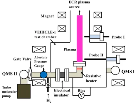
Hydrogen permeation through a reduced activation ferritic steel alloy: F82H has been investigated in a steady state laboratory-scale plasma device: VEHICLE-1 under some of the reactor-relevant conditions. In PDP experiments, the hydrogen permeation flux is measured by a quadrupole mass spectrometer (QMS) at the downstream side. The plasma density is of the order of 109-1010 cm-3 and the electron temperature is ~3 eV. The particle bombarding energy is controlled by a negative bias voltage applied on the membrane flange. The net hydrogen implantation flux is estimated by taking into account the hydrogen species mix and reflection coefficient data. In GDP experiments, the upstream hydrogen gas pressure is 1.3×10⁴-105 Pa measured by an absolute pressure gauge and the hydrogen permeation flux is measured by another QMS in VEHICLE-1 chamber. For all the permeation experiments, the
II
membrane samples made of F82H and SUS304 are prepared in the same dimensions as those commercially available conflat flanges with an outer diameter of 70 mm, except that a circular area of 35 mm in diameter inside the knife-edge is machined down to thicknesses of 0.5 to 5 mm. A resistive heater is set beneath the membrane and the sample temperature varies from 220 oC to 520 oC.
The hydrogen transport parameter data taken for SUS304 have been found to be in good agreement with the literature data, which means that the experimental setup on VEHICLE-1 is valid for the evaluation of other first wall candidate materials. Both GDP and PDP data through F82H show thickness dependence, suggesting that hydrogen permeation is diffusion- limited under some of the reactor-relevant conditions. The hydrogen transport parameters such as permeability, solubility, diffusion coefficient and surface recombination coefficient have been successfully measured for F82H. In particular, the surface recombination coefficient, which is essential to correctly predict the hydrogen isotopes permeation flux through the first wall, has been experimentally measured for the first time. Using the measured parameters and the steady state permeation model, hydrogen isotopes permeation flux and the dynamic wall inventory under some of the reactor-relevant conditions have been evaluated.
The surface effects on hydrogen PDP have been investigated from two aspects: surface contamination and morphology. A new model has been proposed to interpret the surface condition effects. Thick surface impurity film has been found to act as a second layer for diffusion and reduce the permeation flux in both laboratory and tokamak experiments. A decrease in steady state permeation flux has been measured when increasing plasma-facing surface area, which is in agreement with the theoretical prediction, i.e., the steady state permeation flux is inversely proportional to the square root of surface area. Experiments indicate that the permeation flux can be further reduced by simultaneous surface oxidization and area modification.
As a proof-of-principle experiment, first wall particle flux measurements in the QUEST spherical tokamak have been conducted, using a permeation probe that employs F82H as the
III
membrane and also SUS304 as a comparative reference membrane. Permeation measurements have been done during the conditioning steady state discharges heated with 2.45 GHz and 8.2 GHz ECR. Diffusion and surface recombination coefficients measured in VEHICLE-1 are used to interpret the results from the permeation probe measurements in QUEST. A much shorter PDP breakthrough time and higher steady state permeation flux have been found for F82H than SUS304, which is consistent with the results from VEHICLE-1 experiments. The effect of plasma heating power indicates that the steady state permeation flux is roughly proportional to the square root of the implantation flux. The F82H permeation probe shows good sensitivity to the variation of plasma parameters.
Bi-directional hydrogen (H) permeation has actually been demonstrated for the first time in a laboratory-scale steady state plasma facility. Gas-driven permeation hydrogen flows from the gas-facing surface into helium, argon and hydrogen plasmas have been measured. For the bi-directional hydrogen permeation experiments, the membrane temperature is set between 550 and 600 oC, the hydrogen gas pressure for GDP is increased to 9.3×10⁴ Pa. At the plasma side, the electron temperature is raised up to ~10 eV for the improved sensitivity of Hα spectroscopy. Experiments indicate that gas-driven permeation can take place in the opposite direction of plasma-driven permeation, which then results in an unwanted increase in edge plasma density. A one-dimensional diffusion code: DIFFUSE has been utilized to simulate the experiment. The modelling result has been found to be in relatively good agreement with the experimental data. Hydrogen PDP flow from the plasma side to the gas side has been detected as well. The driving pressure for GDP has been found to decrease slower when a bias is applied to the sample, suggesting a PDP flow into the gas side.
DIFFUSE-code has extensively been executed, employing multiple hydrogen isotopes (D/T) for bi-directional permeation. The input data for DIFFUSE are such that the thickness of a membrane made of α-Fe (used as a surrogate of F82H) is 5 mm, the D/T inflows from the upstream (plasma-facing) side are driven by PDP with D/T implantation fluxes of 5 × 10¹⁵ D/cm2/s and 5 × 10¹⁵ T/cm2/s at a bombarding energy of 100 eV. The T inflow from the downstream (gas-facing) side is driven by GDP. Results indicate that the same isotopic
IV
species interact with each other in the two counter flows. Deuterium flow appears to be independent of these tritium flows, driven by its own concentration gradient.
Re-analysis of the tritium flows in a FLiBe loop has been performed, taking into account tritium leakage from the first wall. The tritium pressure has been found to be ~1.1×10³ Pa, which is ~10% of the tritium equilibrium pressure in FLiBe at a temperature of 527 oC. Under these conditions, ~68% of the bred tritium will be released at the plasma side by GDP. Assuming a particle reflection coefficient of 0.5 and a total incident flux of 2.0×10¹⁶ D&T/cm2/s, the first wall recycling rate has been estimated to be 1.006.
V
Acknowledgement
Foremost, I would like to express my sincere gratitude to my advisor Prof. Yoshihiko Hirooka for his guidance, caring, and providing me with an excellent opportunity to learn from him. I will cherish all the moments when we worked together and all the fun we had together.
My deeply thanks also goes to my vice-advisor Dr. Naoko Ashikawa for her supports to my experiments and her help with my life in Japan.
I want to express my gratitude to the rest of my thesis committee: Prof. Yukio Nakamura, Prof. Hideki Zushi, Prof. Yousuke Nakashima and Dr. Teruya Tanaka for their insightful comments, suggestions and questions, which are extremely important to improve my thesis.
I am very grateful to Prof. Takeo Muroga, Prof. Akio Sagara, Prof. Suguru Masuzaki, Prof. Izumi Murakami, Prof. Shoichi Okamura, Prof. Nagato Yanagi, Dr. Daiji Kato, Dr. Takuya Nagasaka, Dr. Masayuki Tokitani, Dr. Sadatsugu Takayama and Dr. Juro Yagi for their helps and caring.
I would like to thank Japan Atomic Energy Agency, Naka Fusion Institute for the material preparation.
I would like to express my thanks to the Graduate University for Advanced Studies (SOKENDAI) and the National Institute for Fusion Science (NIFS) for the financial supports during my PhD study.
A special thanks goes to Prof. Guang-nan Luo for his encouragements and supports for this oversea PhD study.
I would like to express my deeply gratitude to my friends, Erhui Wang, Tingfeng Ming, Pengfei Zheng, Yanfen Li, Shigenori Mizuno san, Hao Wang, Haiying Fu, Xiaodi Du, Hongming Zhang, Xianli Huang, Shaofei Geng, Chunfeng Dong, Xiang Ji, Xiaobing Ding, Botsz Huang for their encouragements and helps. I could not have imagined living in a foreign country without you.
VI
I dedicate this thesis to
my family and my wife, Sisi,
for their constant support.
I love you all.
VII
Contents
Abstract
... IAcknowledgement
... VContents
... VIIChapter 1 Introduction
... 11.1. Nuclear fusion research... 2
1.2. Reactor blanket and the first wall ... 4
1.3. Hydrogen isotopes permeation issues ... 8
1.4. Objectives of this work ... 15
1.5. Outline of the thesis ... 16
Reference ... 17
Chapter 2 Theories on hydrogen isotopes transport through solids
... 232.1. Entering and release of hydrogen isotopes in solids ... 24
2.1.1. Reflection and implantation ... 24
2.1.2. Solution ... 27
2.1.3. Diffusion and trapping ... 28
2.1.4. Surface recombination ... 29
VIII
2.2. Steady state permeation models ... 29
2.3. Isotope effects ... 32
2.4. Summary ... 34
Reference ... 35
Chapter 3 Hydrogen gas- and plasma-driven permeation through a
reduced activation steel alloy F82H
... 373.1. VEHICLE-1 linear plasma facility and the permeation experimental setup ... 38
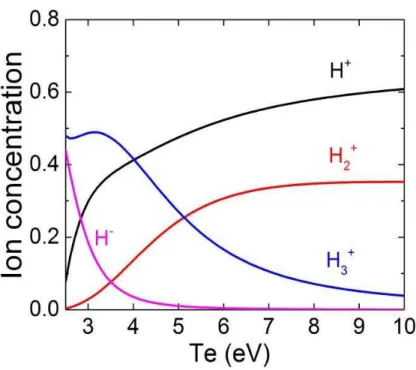
3.2. Characterization of hydrogen plasmas in VEHICLE-1 ... 40
3.3. Sample preparation and analysis methods ... 45
3.4. Gas-driven permeation ... 46
3.5. Plasma-driven permeation ... 55
3.6. Surface effects on plasma-driven permeation ... 61
3.6.1. Models on surface modification effects on PDP... 61
3.6.2. Surface condition effects experiments ... 64
3.7. Discussion ... 68
3.7.1. Comparison of the PDP behavior for F82H and SUS304 ... 68
3.7.2. Compound surface condition effects on PDP ... 70
3.7.3. Comparison of hydrogen PDP and GDP through F82H. ... 71
3.8. Summary ... 73
Reference ... 74
Chapter 4 Plasma-driven permeation through F82H in QUEST
... 794.1. QUEST spherical tokamak ... 80
IX
4.2. Permeation experimental setup in QUEST ... 81
4.3. Results and discussion ... 84
4.3.1. PDP through F82H and SUS304 membranes in QUEST ... 84
4.3.2. Effect of plasma heating power ... 88
4.3.3. Diffusivity measurements for F82H from the PDP data taken in QUEST ... 89
4.4. Summary ... 93
Reference ... 94
Chapter 5 Bi-directional hydrogen (H) permeation experiments and
modelling
... 975.1. Introduction ... 98
5.2. Experimental methods ... 98
5.3. Hydrogen gas-driven permeation into Ar and He plasmas ... 99
5.4. Hydrogen gas-driven permeation into hydrogen plasma side ... 101
5.5. DIFFUSE-code calculation for the hydrogen GDP flow ... 103
5.5.1. DIFFUSE-code ... 103
5.5.2. Input data and assumptions for the bi-directional permeation calculations ... 104
5.5.3. Calculation results and discussion ... 105
5.6. Hydrogen plasma-driven permeation into hydrogen gas side... 107
5.7. Summary ... 109
Reference ... 110
Chapter 6 Bi-directional hydrogen isotopes (D/T) permeation through the
first walls of fusion reactors
... 111X
6.1. Introduction ... 112
6.2. Isotopes effects on permeation... 112
6.2.1. Diffusivity and solubility ... 112
6.2.2. Recombination coefficient ... 113
6.2.3. Competition of the isotopes for traps ... 114
6.3. Modeling of bi-directional permeation involving multiple hydrogen isotopes ... 115
6.4. Re-evaluation of the tritium pressure in FLiBe blankets ... 118
6.5. Re-evaluation of hydrogen isotopes permeation through the first wall of FLiBe blankets ... 121
6.5.1. Evaluation of the hydrogen isotopes permeation fluxes ... 121
6.5.2. Evaluation of the possible impact of GDP on first wall recycling ... 124
6.6. Summary ... 125
Reference ... 126
Chapter 7 Summary and outlook
... 1297.1. Summary ... 130
7.2. Outlook ... 131
List of publications
... 1331
Chapter 1
Introduction
2
1.1. Nuclear fusion research
Nuclear fusion is a reaction in which atomic nuclei with lower mass collide to form a new type of atomic nucleus, accompanied by a release or absorption of energy. The primary energy source for stars is hydrogen fusion, which is also considered to be one of the most promising candidate sources to provide safe, environmentally friendly and economical energy for human beings [1-3]. Of all the possible fusion reactions the deuterium-tritium (D- T) reaction is the most attractive one because tritium and deuterium can react at relatively low energy, generating α-particle (He), neutron (n) and a large amount of energy [1]:
2 3 4 1
1D + T1 2He (3.5 MeV) + n (14.1 MeV)0 , (1.1)
where the energies shown are kinetic energies of the reaction products. In a fusion plasma, the energy carried by the α-particle can be transferred to the plasma by collision so that the confined plasma can be persistently heated. Lawson [4] showed that a fusion plasma would burn to self-sustaining (ignition) if the product of energy confinement time �� [s] and plasma density n [m-3] exceeded a given threshold for a fixed plasma temperature T [keV]. Because
�� itself is a function of temperature, the ignition condition is more usually expressed as:
21 3
E ~ 5 10 m keV s
n T , (1.2)
i.e., to achieve ignition, the high-temperature, high-density plasma must be confined in a relatively long time. In a star, the plasma is confined by the force of gravity due to the huge amount of matter. On the earth, two leading ideas are proposed to obtain usable energy from fusion reactions: magnetic confinement fusion (MCF) and inertial confinement fusion (ICF).
In MCF systems, the plasma is held by magnetic field in desired configurations. The core plasma density is kept at ~1020 m-3 for several seconds of confinement time to fill Eq. (1.2). From 1950’s, various ideas of MCF have been proposed, among which tokamak and
3
stellarator are considered to be the most promising concepts to yield commercial fusion reactors. Many large and medium size MCF devices have been built, e.g., JET [5], JT-60[6], LHD [7], DIII-D [8], ASDEX-U [9], EAST [10], KSTAR [11] and QUEST [12]. Shown in Fig.1.1 is the International Thermonuclear Experimental Reactor (ITER) [13], which is under construction in Cadarache, France. ITER is planned to be the first experimental reactor to demonstrate extended burning of D-T plasmas at a few hundred MWs of fusion power and technology essential to a reactor in an integrated system, and to test nuclear components required to utilize fusion energy for practical purposes [14].
The MCF device beyond ITER will aim to demonstrate electricity production (DEMO reactor). SlimCS [15], PPCS-A to PPCS-D [16] and ARIES-AT [17] are several examples for tokamak type DEMO concepts. Stellarator type reactor concepts have also been proposed, for example the Force-Free Helical Reactor (FFHR) series concepts being developed by National Institute for Fusion Science in Japan [18]. Recently, some researchers suggested that a test reactor between ITER and DEMO may be necessary in the roadmap to the
Figure 1.1 Design of ITER tokamak [13]
4
realization of fusion energy. These concepts include the China Fusion Engineering Test Reactor (CFETR) [19] and the Fusion Nuclear Science Facility (FNSF) [20], which aim to provide an integrated, continuously fusion nuclear environment that can be used to investigate plasma material interactions, tritium fuel management, and power extraction, etc [20].
In contrast to MCF, ICF goes a different way to fill the Lawson Criterion. Fuel targets containing a mixture of deuterium and tritium are heated and compressed by high-energy laser lights or laser-produced X-rays to generate high temperature, high density plasmas. For the ICF plasmas, the density is usually larger than ~1031 m-3 while the confinement time is shorter than 10-10 s [21]. By present, the largest and most energetic ICF device built is the National Ignition Facility (NIF) located at the Lawrence Livermore National Laboratory in Livermore, USA [22]. Recently a fuel capsule gave off more energy than was applied to it in NIF, which is an important milestone towards commercialization of ICF [23].
On the whole, considerable progresses have been achieved for both MCF and ICF in the last 50 years, but a lot of physics and technical issues are still needed to be addressed to realize fusion energy as a power source. This thesis mainly makes a contribution to MCF research in the areas of plasma-wall interaction physics and reactor blanket engineering.
1.2. Reactor blanket and the first wall
No matter which concept is used to develop a fusion power plant, tritium, one of the fuels for D-T reaction, must be artificially produced in reactors because it is a quite limited resource due to its short half-life [24]. Tritium can be produced by the reactions between neutron and lithium (Li) isotopes as follows [25]:
1 6 3 4
0n + Li3 1T + He + 4.8 MeV2 (1.3)
1 7 3 4 1 '
0n + Li3 1T + He + n - 2.5 MeV2 0 (1.4)
5
Present developments in the context of fusion propose generating tritium are based on the reaction (1.3) because the reaction with the more abundant 7Li is endothermic and has a smaller cross-section for neutrons with an energy lower than 5 MeV [25].
Lithium metal/alloys or lithium compounds are stored in the blanket structures so that lithium can capture fusion neutrons to generate tritium. This process is called tritium breeding, because the fusion neutrons come from the previous D-T reactions which consume tritium. Shown in Fig.1.2 is the 3D view of the FFHR2 reactor concept [18]. It can be seen that all the internal surface areas is covered by blanket structures for the highest achievable tritium breeding ratio (TBR). From the viewpoint of commercial operation, a fusion reactor must be tritium self-sustainable, which requires a TBR larger than 1 [24].
Figure 1.3 shows a module of the FFHR2 outboard blanket and (b) a schematic diagram of the blanket structure [26]. The definition of the “first wall” will be different for magnetic fusion devices up to ITER and for those to be built thereafter for power generation. It is widely recognized that ITER will generate fusion power which, however, is not intended to be converted into electrical power. This is because no complete blanket concept will be
Figure 1.2 The FFHR2 reactor concept [18]
6
implemented except for test blanket modules to cover only a fraction of the surface area exposed to burning plasmas. In this case, the definition of the first wall is nothing but a vacuum chamber wall to separate DT-plasma from the environment. As opposed to that, for fusion power reactors, essentially all the internal surface areas must be covered by blanket structures for the highest achievable tritium breeding ratio. The first wall is thus redefined as the plasma-facing walls of blankets.
Figure 1.3 (a) A module of the FFHR2 outboard blanket and (b) a schematic diagram of the blanket structure [26].
7
Reduced activation ferritic steels (RAFSs) such as F82H are the candidate materials for the first wall of reactors, due to the following advantages: (1) reduced activation: after operation to 45 MWa/m2 in FFHR and 100 years cooling, the surface dose rate of the RAFSs is less than 10 µSv/h, which satisfies the shallow land disposal limits [27]; (2) swelling resistance: 1 vol.%/100dpa as compared with 1 vol.%/10dpa in stainless steels [28] and (3) relatively high thermal conductivity, which allows a relatively thick first wall design [29].
From the viewpoint of efficient heat exchange, the blanket operational temperature should be close to the maximum temperature at which the structural material can maintain its strength. For RAFSs, the operational temperature would be around 500 °C. Shown in Fig. 1.4 is the relation between stresses and the wall thickness [30]. The sum of thermal stress and stress arising from internal pressure has a minimum value at ~5 mm, which is considered to be the optimum thickness in this design configuration. Table 1.1 shows some of the parameters for the breeding blanket concepts [31]. It can be found that in most of the recent reactor studies, including FFHR, the first wall is designed to be 5 mm or even less, although these concepts employ various first wall materials such as vanadium alloy (V-alloy) and silicon-carbide-fiber-reinforced silicon carbide composites (SiCf/SiC).
Figure 1.4 Stresses in the first wall as a function of thickness [30].
8
Table 1.1 Some of the breeding blanket concepts (re-edited from [31])
He cooled pebble bed
Water cooled pebble bed
Water cooled Pb-17Li
Self- cooled FLiBe
Self- cooled
Li
He cooled Li
He cooled pebble
bed
Device Tokamak DEMO
Tokamak DEMO
Tokamak DEMO
Helical
FFHR-2 Tokamak
Tokamak
LAR design Tokamak
Tritium breeder
Li
Ceramics Li2TiO3 Pb-17Li FLiBe Li Li Li4SiO4
Structural material
ODS steel, RAFS
F82H, ODS RAFS
EUROFER RAFS
RAFS
V-Alloy V-Alloy
V-Alloy
(W coating) SiCf/SiC
Fusion
power (GW) 3.6 2.3 3.6 1 5.3 4.5
Neutron load
(MW/m2) 4.4 (max) 5.0 (max) 6.6 (max) 1.7 (ave) 10 (max) 11 (max) 3.5 (max)
Surface heat load (MW/m2)
0.8 (max) 1.0 (max) 1.2 (max) 0.1 (ave) 2 (max) 2.73 (max) 0.6 (max)
FW thickness
(mm)
5 3 4 5 4 1.5+1(W),
tubing 3
FW temperature
(°C)
630 ~600 590 750 754 697 913
Coolant He H2O H2O FLiBe Liq. Li He He
Pressure 8 Mpa 25 MPa 15.5 MPa 0.6 Mpa 0.5 MPa 15 MPa 8 MPa
Ref. [32] [33] [32] [30] [34] [35] [36]
1.3. Hydrogen isotopes permeation issues
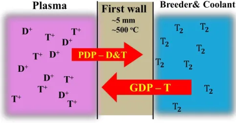
As shown in Fig. 1.3 (b), the first wall will be exposed to edge plasma at elevated temperatures on the one hand, and also it will be in contact with a liquid breeder or coolant, either one of which contains bred tritium on the other hand. One then predicts that the first
9
wall will be subjected to hydrogen isotopes penetration in the two opposite directions. From the edge plasma side, deuterium and tritium flow into the blanket by the mechanism referred to as PDP (for plasma-driven permeation), and from the blanket bred tritium flows into the plasma side by GDP (for gas-driven permeation), as shown in Fig.1.5.
It is important to note that (1) PDP necessitates an isotope separation capability in the tritium recovery loop of a reactor, which then complicates the entire fuel recycle system; and (2) GDP, acting as fueling, may cause an edge plasma density rise.
The behavior of hydrogenic particles implantation-driven permeation through a membrane has been investigated by researchers for decades. Some permeation experiments were performed using ion gun facilities, in which case the ion energies were several to tens of keV and the ion fluxes were usually lower than 1015 cm-2s-1. Here such kind of permeation behavior is referred to as ion-driven permeation (IDP), to differentiate from plasma-driven permeation, which has relatively lower implantation energies. In those IDP experiments the membrane materials included pure iron, stainless steel, nickel, vanadium, tungsten and iron+coatings. Membrane thicknesses varied from 10 µm to 500 µm and target temperatures were kept between room temperature and 900 ℃, as summarized in Table 1.2.
Figure 1.5 PDP and GDP of hydrogen isotopes through the first wall
10 Table 1.2 A summary of some of the IDP experiments.
Material
Sample Temperature
(K)
Incident Flux (cm-2s-1)
Eion
(eV)
Membrane Thickness
(mm)
Permeation Flux
(cm-2s-1) Ref. SUS316L 670 5.70×10¹⁴ 100-2000 0.05 8.55×10⁹~1.71×10¹⁰ [37]
Ni 300-1073 4.00×10¹⁴ 30k
0.01 <3×10¹²
[38] 0.02 <2×10¹²
0.05 <1×10¹² 0.1 <4×10¹¹ Ni 373-1273 0.2-1.1×10¹⁵ 1-2.5k 0.122 and
0.124 10
10~ <1013 [39] Pure Fe
295-610 0.3-6×10¹³ 750~3000
0.1 0-2×10¹²
[40] Pd coating
+Fe 10nm+0.1 No
Fe+
Pd coating 0.1+10nm 0-9×10
12
Au coating
+Fe
10nm+0.1 0~2×10¹²
Fe ~400 10
14 (100eV)
1015 (2000eV) 100-2000 0.1 <4×10
13 [41]
W 598-660 4×10¹⁴-1×10¹⁵ 100-2000 0.025 <8×10¹⁰ [42]
Literature data show that the temperature dependence of permeation fluxes differed from material to material. For SS316L [37,43] and nickel [44,45], the permeation flux ratios would become larger as the temperature increased. However, conflict trends were reported for pure iron [39,40] and tungsten [42,46] in different papers, which may be resulted from different experimental conditions, e.g., ion implantation energies. The effects of incident energy were also investigated. For some materials, e.g., SS316L [38], nickel [39] and tungsten [39,40], permeation flux increased as the incident energy increased. However, it should be noted that the ion energy effect may be not the same if the permeation regime changes, which is
11
possible due to the variation of incident energy and sample temperature [47]. One example is that the ion energy dependence became not noticeable at very high energy range, e.g., several keV, or at high temperatures [37,39]. For most of these experiments, the permeation flux ratios were proportional to the incident fluxes [37,39-43].
These IDP experiments provide a large amount of data on hydrogen isotopes permeation through materials, which can be good references for researchers. Based on these data, several models are proposed to explain the permeation behavior, including implantation, diffusion and surface recombination, which will be introduced in detail in Chapter 2. However, it should be pointed out that the ion fluxes were too low and the incident energies were too high in these IDP experiments, making them not comparable with the PWI conditions for the first wall in a fusion reactor.
Generally, the edge plasma density in the scrape-off layer (to be referred to as SOL) of a magnetic fusion device is of the order of 1013 cm-3 and the cross-field diffusion coefficient is typically of the order of 103 cm2s-1. Assuming that the thickness of SOL is a few cm, the cross-field particle flux to the first wall may be estimated to be of the order of 1016 H cm-2s-1. A similar order estimate can be obtained from the cross-field transport scaling law observed in Alcator C-Mod [48]. From 1980s, researchers started to investigate plasma-driven permeation issues using low energy, high flux plasmas, which is more relevant to the reactor plasma-wall interaction (PWI) conditions. Those data as summarized in Table 1.3.
Membrane bias effects were investigated in some of these works. The permeation fluxes were found to decrease if the bias voltages were higher than 50 V or more [50,53,55,56], which suggests that the PDP flux ratio is not directly related to the ion implantation range, and the surface condition may play an important role. After long-time plasma bombardment, a variation of the steady stage permeation flux was measured under the same bias voltage [50,56]. This change was attributed to the modification of upstream surface composition, which decides the recombination coefficient. For nickel [54] and Kovar [56], the permeation flux ratios increased as the temperatures increased. But a transition point at 480K was found for SUS304, which was interpreted as a shift from diffusion limited-regime to
12
recombination-limited regime [51]. It must be noted that although RAFSs are the candidate first wall materials for fusion power reactors, PDP data on RAFSs are quite limited in the existing database.
Table 1.3 A summary of some of the PDP experiments.
Material
Sample Temperature
(K)
Incident Flux (cm-2s-1)
Eion
(eV)
Membrane Thickness
(mm)
Permeation Flux (cm-2s-1)
Ref.
SUS304 683 8.8×10¹⁶ 20 1.5×10¹⁵ [49]
SUS304 673 6.8×10¹⁶
20-40
0.25
3.2×10¹⁴
[50]
150 ~2×10¹³
SUS304 ~400-673 Ne<~5×1010 cm-3 <10 0.01 6.3×10
14
(at 480K) [51]
Ni 523 Ne<~5×1010 cm-3 <10
0.02 ~9×10¹⁴
[52] 0.05 ~6×10¹⁴
0.2 ~2×10¹³
Ni & Va 1073 Ne=~5×1010 cm-3 few-250 0.1 <2×10¹⁷ [53]
Ni 473-773 3×10¹⁶ 100 0.3 <5×10¹³ [54]
Nb 983
3×10¹⁵ and (5-10) ×1016 hot
atoms
few-200 0.3 <3.5×10¹⁵ [55]
Kovar
773 ~5.7×10¹⁶ 20
0.25 6.10×10¹³
[56]
TiB2+Kovar 0.015+0.25 1.50×10¹³
Nb and
Nb/Pd 775-975 2.5×10
16 10~100 0.025 and 0.1 <6.25×10¹⁵ [57]
13
As described at the beginning of this section, for those blankets employing liquid breeder to serve as a coolant as well (self-cooled breeder), the first wall is to be exposed to tritium bred in blankets, depending upon its dissociation pressure, which may result in GDP. Shown in Fig.1.6 are the equilibrium tritium partial pressures in lithium and lithium compounds at a temperature of 800 K [58]. For FLiBe, which is the candidate breeder for a FFHR reactor [30], the tritium dissociation pressure is ~104 Pa at a (T/M) concentration of ~0.1 ppm.
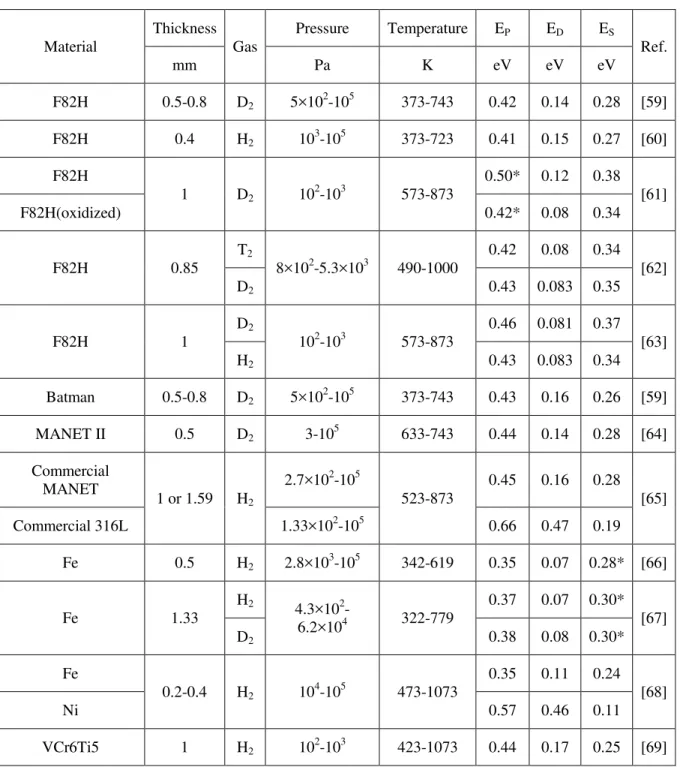
Shown in Table 1.4 are some experimental data on gas-driven permeation for various metals. Compared with the database of PDP, the data on hydrogen isotopes GDP through metals are much more comprehensive and updated. Hydrogen transport parameters in several kinds of RAFSs and vanadium alloys are also available. Those GDP experiments were performed with a driving pressure of 102-105 Pa at a temperature of 322-1073 K. Some specific aspects such as trapping [59] and coating [63] were also investigated. In general, studies of RAFSs report relatively consistent transport properties of hydrogen isotopes.
Figure 1.6 Equilibrium tritium partial pressures in lithium and lithium compounds [58].
14
However, due to the limitation of GDP setups, the surface recombination process is difficult to address in these studies.
Table 1.4 A summary of some of the GDP experiments.
Material
Thickness Gas
Pressure Temperature EP ED ES
Ref.
mm Pa K eV eV eV
F82H 0.5-0.8 D2 5×10²-105 373-743 0.42 0.14 0.28 [59]
F82H 0.4 H2 103-105 373-723 0.41 0.15 0.27 [60]
F82H
1 D2 102-103 573-873
0.50* 0.12 0.38 [61]
F82H(oxidized) 0.42* 0.08 0.34
F82H 0.85
T2
8×10²-5.3×10³ 490-1000
0.42 0.08 0.34 [62]
D2 0.43 0.083 0.35
F82H 1
D2
102-103 573-873
0.46 0.081 0.37 [63]
H2 0.43 0.083 0.34
Batman 0.5-0.8 D2 5×10²-105 373-743 0.43 0.16 0.26 [59]
MANET II 0.5 D2 3-105 633-743 0.44 0.14 0.28 [64]
Commercial MANET
1 or 1.59 H2
2.7×10²-105
523-873
0.45 0.16 0.28 [65]
Commercial 316L 1.33×10²-105 0.66 0.47 0.19
Fe 0.5 H2 2.8×10³-105 342-619 0.35 0.07 0.28* [66]
Fe 1.33
H2
4.3×10²-
6.2×10⁴ 322-779
0.37 0.07 0.30* [67]
D2 0.38 0.08 0.30*
Fe
0.2-0.4 H2 104-105 473-1073
0.35 0.11 0.24 [68]
Ni 0.57 0.46 0.11
VCr6Ti5 1 H2 102-103 423-1073 0.44 0.17 0.25 [69]
* Estimated value from diffusion and solution coefficients
15
In Table 1.4, the terms EP and ED mean the activation energy for permeation and diffusion, respectively. ES is the heat of solution. The detailed physical meaning of them will be explained in Chapter 2. Generally speaking, small activation energy indicates a relatively small temperature dependence of the coefficients, which can explain the different GDP behavior of RAFSs and stainless steel.
In summary, although the parameters such as permeability, diffusivity and solubility have been measured for some of the RAFSs [59-65], significant error can be made in predicting hydrogen isotope permeation flux through the first wall. Literature data on hydrogen transport parameters for RAFSs are limited because all these data are taken only from GDP experiments and the surface recombination process under plasma exposure is not sufficiently investigated. Some of the PDP experiments were run more than 20 years ago and the researchers’ estimations on the edge plasma parameters and operation temperatures of the first wall were not quite accurate. From the viewpoint of fusion engineering, most target materials in those experiments cannot be used as structural material in a fusion reactor. More efforts are needed to establish the database of hydrogen isotopes PDP through RAFSs.
1.4. Objectives of this work
Evaluation of hydrogen isotopes permeation through the first wall is extremely important to the fusion system design work. This PhD thesis research aims (1) to understand the physical mechanisms driving hydrogen isotopes permeation processes; (2) to demonstrate experimentally hydrogen transport phenomena that are predicted for the first wall of a fusion power reactor and (3) to establish a database on hydrogen transport parameters for designing fusion power reactors.
16
1.5. Outline of the thesis
The thesis is arranged as follows: after this introduction chapter, some theories and models on hydrogen isotopes transport through solids will be briefly reviewed in Chapter 2. In Chapter 3, studies on hydrogen gas- and plasma-driven permeation through a reduced activation steel alloy F82H in a laboratory-scale steady-state plasma device: VEHICLE-1 will be presented. The experimental results of PDP through F82H in a medium size spherical tokamak QUEST will be shown in Chapter 4. Chapter 5 includes the hydrogen (H) bi- directional permeation experiments and theoretical calculations. Studies on multiple hydrogen isotopes (D/T) bi-directional permeation through the first walls of reactors will be presented in Chapter 6, followed by a summary of the whole thesis.
17
Reference
[1] J. A. Wesson, Tokamaks, Clarendon Press, Oxford, 3rd edition, 2004. [2] M. Kikuchi, Frontiers in fusion research, Springer-Verlag, London, 2011.
[3] K. Miyamoto, Plasma physics and controlled nuclear fusion, Springer-Verlag, Berlin, 2005.
[4] J. D. Lawson, Some criteria for a power producing thermonuclear reactor. Proc. Phys. Soc. B 70 (1957) 6.
[5] http://www.efda.org/jet/.
[6] http://www-jt60.naka.jaea.go.jp/. [7] http://www.lhd.nifs.ac.jp/.
[8] https://fusion.gat.com/global/DIII-D. [9] http://www.ipp.mpg.de/16195/asdex. [10] http://english.hf.cas.cn/ic/ip/east/.
[11] G.S. Lee et al., Design and construction of the KSTAR tokamak, Nuclear Fusion 41 (2001)1515.
[12] K. Hanada et al., Steady-State Operation Scenario and the First Experimental Result on QUEST, Plasma Fusion Research 5 (2010) S1007.
[13] http://www.iter.org.
[14] Y. Shimomura, ITER towards the construction, Fusion Engineering and Design 74 (2005) 9.
18
[15] K. Tobita et al., Compact DEMO, SlimCS: design progress and issues, Nuclear Fusion 49 (2009) 075029.
[16] D. Maisonnier et al., DEMO and fusion power plant conceptual studies in Europe, Fusion Engineering and Design 81 (2006) 1123.
[17] F. Najmabadi et al., The ARIES-AT advanced tokamak, Advanced technology fusion power plant, Fusion Engineering and Design 80 (2006) 3.
[18] A. Sagara et al., Conceptual design activities and key issues on LHD-type reactor FFHR, Fusion Engineering and Design 81 (2006) 2703.
[19] Y. Wang et al., Overview of fusion energy science research in China, Paper presented at the 16th International Conference on Fusion Reactor Materials, Beijing, China, Oct. 20th -26th, 2013.
[20] Y. K. M. Peng et al., Fusion Nuclear Science Facility (FNSF) Before Upgrade to Component Test Facility (CTF), Fusion Science and Technology 60 (2011) 441.
[21] S. Pfalzner, An introduction to inertial confinement fusion, Taylor & Francis, New York, 2006.
[22] https://lasers.llnl.gov.
[23] O. A. Hurricane et al., Fuel gain exceeding unity in an inertially confined fusion implosion, Nature 506 (2014) 343.
[24] T. Tanabe, Tritium issues to be solved for establishment of a fusion reactor, Fusion Engineering and Design 87 (2012) 722.
[25] D. Fasel et al., Availability of lithium in the context of future D–T fusion reactors, Fusion Engineering and Design 75–79 (2005) 1163.
[26] NIFS research report, NIFS-MEMO-64, 2013, in Japanese.
19
[27] A. Sagara, et al., Materials design and related R&D issues for the force-free helical reactor (FFHR), Journal of Nuclear Materials 258–263 (1998) 2079.
[28] N. Baluc et al., On the potentiality of using ferritic/martensitic steels as structural materials for fusion reactors, Nuclear Fusion 44 (2004) 56.
[29] A. Hishinuma, et al., Current status and future R&D for the reduced-activation ferritic/martensitic steels, Journal of Nuclear Materials 258–263 (1998) 193.
[30] A. Sagara, et al., Studies on FLiBe blanket designs in helical reactor FFHR, Fusion Technology 39 (2001) 753.
[31] Ueda et al., PSI issues at plasma facing surfaces of blankets in fusion reactors, Journal of Nuclear Materials 313–316 (2003) 32.
[32] L. Giancarli et al., Candidate blanket concepts for a European fusion power plant study, Fusion Engineering and Design 49&50 (2000) 445.
[33] S.Konishi et al., DEMO plant design beyond ITER, Fusion Engineering and Design 63- 64 (2002) 11.
[34] Y. Gohar et al., High power density self-cooled lithium–vanadium blanket, Fusion Engineering and Design 49–50 (2000) 551.
[35] C.P.C. Wong et al. A helium-cooled blanket design of the low aspect ratio, Fusion Engineering and Design 48 (2000) 389.
[36] L.V. Boccaccini et al., Advanced helium cooled pebble bed blanket with SiCf/SiC as structural material, Fusion Engineering and Design 49–50 (2000) 491.
[37] H. Nakamura et al., Implantation driven permeation behavior of deuterium through stainless steel type 316L, Journal of Nuclear Materials 258-263 (1998) 1050.
20
[38] T. Tanabe et al., Hydrogen-ion-driven permeation at high temperatures, Journal of Nuclear Materials 128 & 129 (1984) 641.
[39] T. Nagasaki et al., Simultaneous ion and gas driven permeation of deuterium through nickel, Journal of Nuclear Materials 151(1988) 189.
[40] W. M. Shu et al., Coating effect on plasma-driven permeation of hydrogen in iron, Fusion Engineering and Design 28 (1995) 131.
[41] W. M. Shu, Ion-driven permeation of deuterium in Fe-Ti alloys, Journal of Alloys and Compounds 196 (1993) 213.
[42] H. Nakanura et al., Tritium permeation behavior implanted into pure tungsten and its isotope effect, Journal of Nuclear Materials 297 (2001) 285.
[43] B.L. Doyle, D.K. Brice, The influence of displacement damage on deuterium permeation in 316 stainless steel, Journal of Nuclear Materials 145-147 (1987) 288.
[44] K. Yamaguchi et al., Simultaneous ion- and gas-driven permeation of hydrogen isotopes through first wall material, Fusion Engineering and Design 10 (1989) 337.
[45] T. Tanabe et al., Hydrogen-ion-driven permeation at high temperatures, Journal of Nuclear Materials 128 & 129 (1984) 641.
[46] H.T. Lee et al., Ion-driven permeation of deuterium through tungsten under simultaneous helium and deuterium irradiation, Journal of Nuclear Materials 415 (2011) S696.
[47] B.L. Doyle, A simple theory for maximum H inventory and release: A new transport parameter, Journal of Nuclear Materials 111/112 (1982) 628.
[48] B. LaBombard et al., Cross-field plasma transport and main-chamber recycling in diverted plasmas on Alcator C-Mod, Nuclear Fusion 40 (2000) 2041.
21
[49] R. A. Kerst and W.A. Swansiger, Plasma driven permeation of tritium in fusion reactors, J. Journal of Nuclear Materials 122&123, (1984) 1499.
[50] R. A. Causey et al., The effect of surface composition on plasma driven permeation of deuterium through 304 stainless steel, Journal of Nuclear Materials 122&123 (1984) 1547.
[51] M. Takizawa et al., Surface condition effects on plasma driven permeation, Journal of Nuclear Materials 248 (1997) 15.
[52] M. Takizawa et al., Estimation of permeation probability in plasma driven permeation, Fusion Engineering and Design 39–40 (1998) 923.
[53] A. I. Livshits et al., Plasma driven superpermeation of hydrogen through group Va Metals, Journal of Applied Physics 84 (1998) 2558.
[54] R.A. Causey et al., Plasma-driven permeation of deuterium in nickel, Journal of Nuclear Materials 145-147 (1987) 284.
[55] A. Busnyuk et al., Membrane bias effects on plasma-driven permeation of hydrogen through niobium membrane, Journal of Nuclear Materials 290–293 (2001) 57.
[56] R. A. Kerst et al., Comparison of plasma and gas driven permeation of deuterium through titanium diboride, Journal of Nuclear Materials 135 (1985) 77.
[57] A.A. Skovoroda et al., Plasma-driven superpermeation of hydrogen through Nb membranes: bulk effects, Journal of Nuclear Materials 306 (2002) 232.
[58] S. Fukada et al., Tritium recovery system for Li–Pb loop of inertial fusion reactor, Fusion Engineering and Design 83 (2008) 747.
[59] E. Serra et al., Influence of traps on the deuterium behaviour in the low activation martensitic steels F82H and Batman, Journal of Nuclear Materials 245 (1997) 108.
22
[60] E. Serra et al., Hydrogen behaviour in aged low activation martensitic steel F82H for fusion reactor applications, Materials Science and Technology 14 (1998) 573.
[61] A Pisarev et al., Surface effects in diffusion measurements: deuterium permeation through Martensitic steel, Physica Scripta T94 (2001) 121.
[62] E. Dolinsky et al., Permeation of deuterium and tritium through the martensitic steel F82H, Journal of Nuclear Materials 307-311 (2002) 1484.
[63] T.V. Kulsartov et al., Investigation of hydrogen isotope permeation through F82H steel with and without a ceramic coating of Cr2O3–SiO2 including CrPO4 (out-of-pile tests), Fusion Engineering and Design 81 (2006) 701.
[64] E. Serra et al., Influence of the surface conditions on permeation in the deuterium- MANET system, Journal of Nuclear Materials. 240 (1997) 215.
[65] K.S. Forcey et al., Hydrogen transport and solubility in 316L and 1.4914 steels for fusion reactor applications, Journal of Nuclear Materials 160 (1988) 117.
[66] R. F. Miller et al., Permeation of hydrogen through alpha iron, Metallurgical Transactions A, 6A (1975) 117.
[67] N. R. Quick et al., Hydrogen and deuterium in iron, 49–506°C, Acta Metallurgica 26 (1978) 903.
[68] Y. Yamanishi et al., Hydrogen permeation and diffusion through pure Fe, pure Ni and Fe-Ni alloys, Transactions of the Japan Institute of Metals 24 (1983) 49.
[69] O.G. Romanenko et al., Hydrogen gas driven permeation through vanadium alloy VCr6Ti5, Journal of Nuclear Materials 233-237 (1996) 376.
23
Chapter 2
Theories on hydrogen isotopes transport
through solids
24
In Chapter 1 the phenomena of hydrogen isotopes plasma- and gas-driven permeation through the first wall of a magnetic fusion reactor have been introduced. The databases of gas-, ion- and plasma-driven permeation experiments have been briefly reviewed as well. To understand those data taken in wide ranges of temperature, hydrogen gas pressure and implantation flux, and also to set the scene for the following research report chapters, this chapter reviews some of the physical mechanisms involved in the interaction of hydrogenic particles with solids, their diffusion and trapping in the solids, and the surface recombination allowing them to be released. In the latter part of the chapter, the steady state permeation models and hydrogen isotope effects are shown.
2.1. Entering and release of hydrogen isotopes in solids
2.1.1. Reflection and implantation
When energetic hydrogen atoms or ions impinge on the first walls, a fraction of them are reflected in a time of ≤ 10-12 s [1]. The particle reflection coefficient RN is defined as the number of all backscattered particles N divided by the number of incident particles N0. As shown in Fig. 2.1, the particles backscattered have distributions in energy E, exit polar angle β, exit azimuthal angle φ and charge state qi, depending on the incident energy E0 and angle α, which may be described by [1,2]:
( 0, ; , , , i)
f E E q (2.1)
Then RN can be obtained by integrating the distributions:
0 / 2 2
0 0
0 0 0
( , ) ( , ; , , , )sin
E
N i
i
R E dE d d f E E q
(2.2)25
The particles which are not backscattered are implanted into the walls. These particle will be slowed down by transferring energy to the target electrons (electronic stopping), or by interaction with the target atom core (nuclear stopping). The mean range of implantation ions may be calculated by [3]:
0
0
1
( )
E dE
d n
S E (2.3)where E0 is the incident energy, n is the particle number and S(E) is the total stopping cross section from electronic and nuclear stopping.
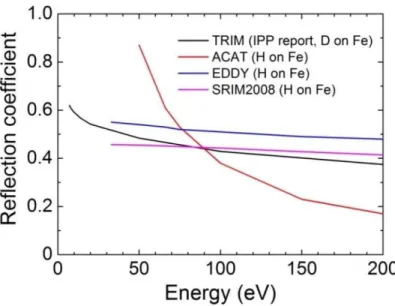
Based on the binary collision approximation (BCA) [4], several Monte Carlo simulation codes have been developed for plasma-wall interaction applications, for example, TRIM [5], ACAT [6] and EDDY [7]. Shown in Fig.2.2 are the calculation results for reflection coefficient of hydrogenic particles on pure iron surface by these codes. The calculated reflection coefficient decreases as an increase of implantation energy when E0 is larger than 10 eV. Figure 2.3 shows one calculation on hydrogen implantation profile in iron by SRIM2008 [8] and EDDY. In general, the calculation results given by these codes are in good consistency.
Figure 2.1 Backscattering of an ion with incident energy E0 from the surface of a solid (re-plot from [1].)
26
Figure 2.2 Particle reflection coefficient of hydrogen on iron estimated by the Monte Carlo codes. For the IPP report, see [5].
Figure 2.3 Calculated hydrogen implantation profile in iron by SRIM2008 and EDDY codes. The implantation energy is 100 eV.
27
Figure 2.4 Schematic energy diagram for hydrogen in metals. (Re-plot from [3]). US, UC, Ut and UP are the enthalpies of solution, chemisorption, trapping and precipitation. UM is dissociation energy and UD is the activation energy for diffusion.
2.1.2. Solution
For hydrogen gas and solids in thermodynamic equilibrium, the hydrogen solubility in metal is proportional to the square root of the partial pressure of the gas (Sieverts’ law [9]) and the bulk concentration C can be given by:
C S p , (2.4) with S donating the solubility expressed by [3]:
0exp( )
US
S S
kT , (2.5) where US is the enthalpy of solution, which is positive for endothermal hydrogen-solid system and negative for exothermal case.
28 2.1.3. Diffusion and trapping
The dissolved hydrogen atoms may migrate in the host lattice, or be trapped by defects and impurities in the lattice. Figure 2.4 shows a schematic energy diagram for hydrogen in metals. It can be seen that the trapping sites expose a higher binding energy than regular solution sites. The behavior of one-dimensional hydrogen transport through a solid with trapping sites can be described by the following equations [10]:
2 2
( , )
( , ) ( , )
( ) C x tt ( , )
C x t C x t
D T G x t
t x t
(2.6)
2 0
( , ) ( , ) ( , )
( ) ( , ) exp( / )
e
t t
t t
C x t C x t C x t
D T C x t U kT
t
(2.7)
( , ) 0( ) ( , )
e
t t t
C x t C x C x t (2.8) where C(x,t) and Ct(x,t) are the concentrations of mobile and trapped atoms as a function of position x and time t; D is the diffusion coefficient; T is the temperature; G(x,t) is the hydrogen implantation profile; Ct0(x) and Cte(x) are the concentrations of intrinsic and empty trapping sites, respectively; is the mean distance between trapping sites; is the jumping frequency; k is Boltzman’s constant and Ut is the de-trapping energy. Equation (2.6) indicates that trapping sites introduced by neutron or energetic particle bombardment will only affect the initial transient permeation behavior.
The diffusion coefficient D can be derived from the “random walk” model, in which case D is given as [14]:
0exp( )
UD
D D
kT (2.9) where D0 is the pre-exponential containing the jumping frequency and lattice structure information, and UD is the activation energy for diffusion.
29 2.1.4. Surface recombination
Hydrogen is released from the surface of a solid via the recombination of dissolved atoms to a hydrogen molecule. The recombination flux (i.e. re-emission flux) J- is proportional to the square of the bulk concentration C at the surface [3]:
2
J
K
r C
(2.10) with the recombination coefficient Kr.Based on the idealized energy diagram shown in Fig 2.4, several models for estimating Kr have been proposed (see Ref. [11], [12] and [13]). Baskes [11] gave a simplified method to calculate the recombination coefficient and the Kr is given as:
0 exp( K )
r
K U
K T kT (2.11)
where UK is the activation energy of recombination and UK = UD+US when UD+US≥ 0; and UK = 2US when UD+US < 0. K0 is a pre-factor which is related to the solubility, diffusivity and surface sticking coefficient:
2.2. Steady state permeation models
The steady state permeation flux J+ controlled by diffusion is generally given by Fick’s first law [14]:
J D C
x
(2.12) For gas-driven permeation, the steady state GDP flux through a thin membrane can be obtained by combining Eq. (2.4) and (2.12):
![Figure 1.4 Stresses in the first wall as a function of thickness [30].](https://thumb-ap.123doks.com/thumbv2/123deta/6159868.103950/18.918.287.599.667.963/figure-stresses-wall-function-thickness.webp)
![Figure 1.6 Equilibrium tritium partial pressures in lithium and lithium compounds [58]](https://thumb-ap.123doks.com/thumbv2/123deta/6159868.103950/24.918.283.651.362.711/figure-equilibrium-tritium-partial-pressures-lithium-lithium-compounds.webp)
![Figure 2.4 Schematic energy diagram for hydrogen in metals. (Re-plot from [3])](https://thumb-ap.123doks.com/thumbv2/123deta/6159868.103950/38.918.202.707.599.880/figure-schematic-energy-diagram-hydrogen-metals-plot.webp)
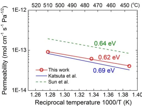
![Figure 3.11 Hydrogen isotopes permeability through F82H . Serra’s [10 ], Pisarev’s [11] and Kulsartov’s [12] data are shown for comparison](https://thumb-ap.123doks.com/thumbv2/123deta/6159868.103950/61.918.240.676.217.646/figure-hydrogen-isotopes-permeability-serra-pisarev-kulsartov-comparison.webp)
