Studies on electrochemical surface modification
for molten-salt blanket system in fusion reactor
Takashi Watanabe
DOCTOR OF
PHILOSOPHY
Department of Fusion Science
School of Physical Sciences
The Graduate University for Advanced Studies
2011(School Year)
Dedication
I dedicate my dissertation work to my family, many friends and exceptional person.
I specially feel of this graduation to my loving parents Tsutomu and Michiko Watanabe. Thank you for all the unconditional love, guidance, support and effort to the wellbeing of your child. I express great appreciation to my uncle Yuji Sakamoto. Words cannot express my gratitude to you. My brothers, Susumu and Akira Watanabe have never left my side and are very special.
I got many young friends in NIFS, Dr. Kinya Saito, Dr. Akiyoshi Murakami, Dr. Kyohei Natsume, Dr. Dongxun Zhang, Mr. Pengfei Zheng, Mr. Yoshimitsu Asahi and Mr. Takeshi Miyazawa. I learned a lot with you every day. There are no days in my life which were felt more joy than the days passed with you. I never forget those days. I believe that you, young generations, will just realize the first fusion reactor. I want to see the day with you.
Finally, Ms. Shinobu Yuki has supported me for 3 years. You have made me what I am today in NIFS.
May this dedication be a small contribution toward the honors you deserve.
i
Acknowledgments
After obtaining a doctoral degree about 10 years ago, I have been working for a national institute. There, I have developed lithium batteries and censor devices. In fact, I wanted to work for development for fusion science and engineering. I had looked for an opportunity for entering to nuclear fusion field before coming to NIFS. However, I could not get it. Then, to find the way to fusion science and engineering, I decided to take a doctoral course in Sokendai and then met Prof. Akio Sagara at NIFS. He opened the way to the fusion science and engineering for me. In other words, thanks to him, I realized my long cherished dream. He showed me current status in fusion reactor development and also led me for the direction of the way ahead. He told me that blanket system will be the most important key technology to realize real fusion reactors. Without his helps and supports, this dissertation would not been completed. My deepest and greatest appreciation goes to Prof. Akio Sagara.
I wish to thank Prof. Takuya Nagasaka, Prof. Akira Nishimura, Prof. Yasuji Kozaki, Prof. Yoshihiko. Hirooka from NIFS, Prof. Akihiro Suzuki
ii
from the University of Tokyo and Dr. Tomoko Ohshima from TYK Co. Ltd. for performing the experiment and sharing fruitful discussions. I thank Mr. Keiichiro Yasuji from Yasuji Inc. for designing the electrochemical reactor. I learned basic electrochemistry from Prof. Tetsuichi Kudo and Prof. Mitsuhiro Hibino from the University of Tokyo, and I discussed Dr. Hiroyuki. Tsujimura from IMSEP Co. Ltd. and Prof. Yasuhiko Ito from Doshisya University about electrochemistry of molten salt. I greatly thank them. Dr. Yuki Edao and Prof. Satoshi Fukada helped me for measurements for hydrogen permeability. I have to give them my thanks a lot. And I learned a lot from the lecture by Prof. Hiroshi Yamada, Prof. Kazuo Kawahata, Prof. Yasuhiko Takeiri, Prof. Osamu Kaneko, Prof. Shinsaku Imagawa, Prof. Kiyomasa Watanabe, Prof. Toshiyuki Mito, Prof. Takashi Mazuzaki, Prof. Hideo Sugama, Prof. Ritoku Horiuchi, Prof. Hideaki Miura, Prof. Suguru Masuzaki.
Prof. Shoichi Okamura, Prof. Takeo Muroga, Prof. Motoyasu Sato, Prof. Nagato Yanagi, Ms. Mayumi Ito and Mr. Kohtaro Uesugi helped me before coming to NIFS, and they were supporting me about various things after starting my research in NIFS. And Ms. Mieko Ukai, Ms. Yuko Kakamu, Ms. Kaoru Banzai, Mr. Tomohito Taki, Ms. Misuzu Yamaguchi, Ms. Tomoko Matsusaki, Ms. Ai Matsubara, Ms. Ai Inoue, Ms. Kyoko Shimazaki, and Ms. Yoko Yamaguhi, I am very grateful to them. I have obtained precious experiences for the 3 years in NIFS and Sokendai. I am obliged to them for the trouble they have taken for me.
Many programs and seminars were organized and held in
iii
SOKENDAI. The staffs from SOKENDAI were also supporting me. Especially, with the aid of the special program for big project research, I could attend an international conference, SOFT 2010 in Portugal, visit ITER construction site in France, and I have achieved large amount of my dissertation work. I express my thanks to Ms. Atsuko Fujisawa and all the stall staffs from SOKENDAI.
Finally, I express my very greatest appreciation to Prof. Masatoshi Kondo and Prof. Teruya Tanaka. Regarding experimental and technical support for this dissertation work, I own it all to them. And I also express my special appreciation to Director-General Prof. Akio Komori and all the NIFS staffs for giving me an opportunity to learn Fusion Science.
March 23, 2012 Takashi Watanabe 渡邉 崇
iv
v
Studies on electrochemical surface modification for
molten salt blanket system in fusion reactor
Takashi Watanabe
Abstract
This doctoral dissertation presents studies for materials for devices in molten fluoride salt blanket system in fusion reactor. When steel materials are employed as a structural material, its corrosion with the fluoride salt is a critical issue. To prevent it, many kinds of ceramics and coating processes have been discussed for compatibility with fluoride salts. However, there are many problems such large area coating over 1000m2, toughness related with peeling and crack, wastes after the coating process and healing of damage parts. In this dissertation, a surface modification method through an electrochemical process using molten fluoride salt itself was proposed to form robust functionally graded material layers at the structural material surface and to overcome these problems.
First, several kinds of oxides and nitrides were thermodynamically considered for compatibility with fluoride molten salts. The thermodynamic consideration predicted that oxides dissolve into molten fluoride salt and that nitride have compatibility with molten fluoride salt. And prior to development of the surface modification process, compatibilities of oxides and nitrides in FLiNaK at 600C were examined in immersion test over 1000 hours using bulk test specimens such Er2O3, Y2O3, Al2O3 and AlN. The results also demonstrated that nitride, AlN, indicated excellent compatibility with molten fluoride salt, FLiNaK. Secondly, coating processes were considered. To form robust graded compositional nitride layers using compositional elements from the structural material, an electrochemical
vi
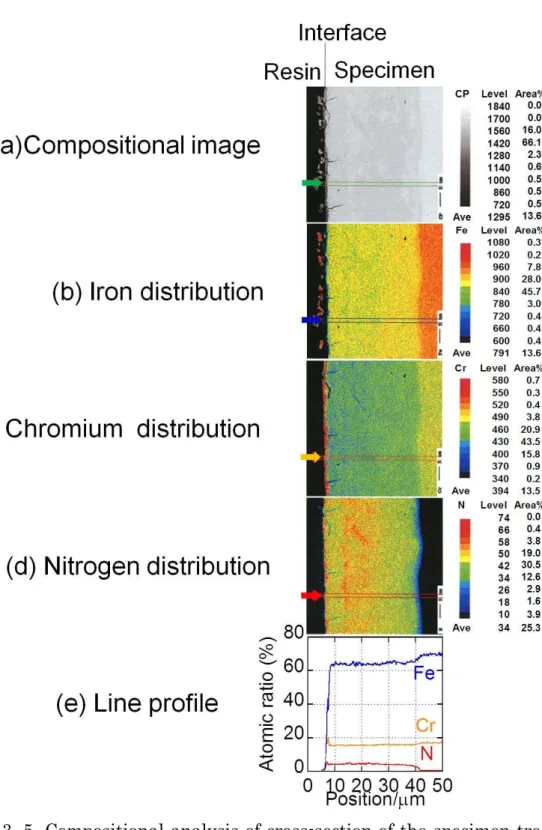
process was proposed. In the process, the surface of structural material is electrochemically treated in molten fluoride salt including Li3N as a nitrogen source. Thirdly, because the experiments using molten fluoride salt have to be conducted in dry environment at high temperature over 500C, an original experimental setup, which consists of a stainless steel reactor, a nickel crucible, thermocouples, heaters and electrodes, was designed and assembled for the experiments. It was installed in a dry Ar gas filled glove box. Aluminum rods were used as counter and reference electrodes. The specimen of 316 stainless steel (ss316) was bound tightly by a nickel wire at an end of nickel rod and it worked as working electrode. The potential standard was determined by the following equilibrium redox reaction of aluminum lithium alloy: Al + Li+ + e- = LiAl. The reaction can cause two half-reactions: oxidation at anodic reaction (loss of electron) and reduction at cathodic reaction (gain of electron). Temperature was controlled by a PID controller connected via cables to the heater. The electrodes were insulated by alumina tubes from the stainless steel reactor vessel. These electrode assembles were connected via cables to a potentiostat and a function generator. Data was recorded by a data logger connected with the potentiostat. Fourthly, cyclic voltammograms were measured using the experimental setup. From the results, the nitriding condition was decided. Fifthly, ss316 surface was treated in a binary eutectic mixture of LiF-KF (FLiK) including Li3N in a potentiostatic condition. The treatment was conducted at 1.0V with respect to lithium redox potential as the standard potential, ie, 1.0V vs. Li/Li+. For the treatment for 100 and 240 minutes, nitrogen was introduced into a depth of 35 and 65m from the surface, respectively. When d[m] is definced as the depth of nitrogen introduced layer and t[min] is defined as the treatment time, it was found that d is approximately proportional to t, ie, d[m] 0.3×t[min]. These specimens were analyzed using analytical methods such X-ray diffraction (XRD), electron probe micro analyzer (EPMA), electron energy dispersive X-ray spectrometry (EDX), X-ray photoelectron spectroscopy (XPS), and scanning
vii
electromicroscopy (SEM). It was revealed that chromium nitride CrN formed selectively. The composition ratios of the nitride layer and the bulk layer were evaluated as Cr17.5wt% - Fe70.8wt% - Ni11.3wt% - Mo0.4wt% and Cr17.0wt% - Fe71.9wt% - Ni9.9 wt % - Mo1.2wt%, respectively. It was also suggested that face-center cubic (fcc) structure transformed to body-centered tetragonal (bct) structure. These results would mean that while the metal composition ratio was mostly held, the phase transformation was caused. Formation of solid solution -Fen(n>8)N was also suggested. Although oxygen impurities were also expected to be introduced to the nitride layer, in fact, oxygen was not introduced into the layer. This means that nitrogen was mainly introduced in the layer through the treatment. Finally, considering the experimental conditions such as temperature, nitrogen concentration and specimen composition, nitride formation was theoretically analyzed based on combination of thermodynamics and electrochemistry. CrN, Cr2N, Fe2N and Fe4N were considered from composition of ss316. Potential-nitride formation diagram and potential-nitrogen ion concentration diagram were made. From discussions on formation of these nitrides based on these conditions, it was theoretically derived that CrN is most stable. This theoretical consideration was well in agreement with the experimental result. In conclusion, these results demonstrate availability of this nitriding method and will allow a guideline for optimization of this nitriding process in molten fluoride salt.
This doctoral dissertation consists of five chapters and one appendix. Chapter 1 presents back ground and proposal of this work, ie, issues and problems on a molten salt blanket system in a fusion reactor. Chapter 2 presents thermodynamical discussion of compatibilities of several ceramics (metal oxides and nitrides). Compatibilities for those ceramics were evaluated based on thermodynamical theory. The prediction indicated that nitrides are compatible with molten fluoride salts. Chapter 3 presents the experimental descriptions and results. Introduction of nitrogen into SS316 specimen surface and formation of nitride layer were described. Chapter 4
viii
presents theoretical explanation based on thermodynamics and electrochemistry. Formation of nitrides about iron and chromium is discussed. Chapter 5 presents conclusions. Appendix presents the results of immersion test using 4 bulk specimens of Er2O3、Y2O3、Al2O3、AlN at 600C over 1000 hours.
In recent years, nitrides have been focused on as fluorescent materials and magnetic materials. Especially, nitrogen solid solution of iron,
-FenN (n>8), is expected as a alternative material without Nd, rare-earth element. Nitriding technique established in this work will be able to be applied not only to blanket system in fusion reactor, but also to many kinds of industrial applications.
ix
Études sur modification électrochimique de surface
pour système de couverture à sel fondu de réacteur
de fusion nucléaire
Takashi Watanabe
Résumé
Cette dissertation doctorale présente des études pour les matériaux pour les appareils dans système de la couverture du sel de fluorure fondu dans le réacteur de fusion nulcéaire. Lorsque les aciers sont employées comme un matériau structural, sa corrosion avec le sel du fluorure est une question critique. Pour l'eviter, beaucoup des céramiques et des processus de revêtement a été discuté concernant la compatibilité avec les sels du fluorure. Cependant, il y a beaucoup de problèmes comme le revêtement de grande surface plus que 1,000 m2, la dureté contre pelage et le fissure, les gaspillages après le processus de revêtement de la couche et la guérison des parties du dégât. Dans cette dissertation, une méthode de la modification de la surface à travers un processus électrochimique qui utilise du sel du fluorure fondu lui-même a été proposée de former des couches robustes de matériels fonctionnels à la surface de matériel de construction et vaincre ces problèmes.
En premier, plusieurs oxydes et nitrures étaient thermodynamiquement considérés sur la compatibilité avec les sels de fluorure fondus. Et avant développement du processus de la modification de la surface, compatibilités d'oxydes et de nitrures avec FLiNaK à 600C ont été examinées par l'essai de l'immersion sur 1000 heures qui utilisent des spécimens de Er2O3, Y2O3, Al2O3 et AlN. Les résultats ont aussi démontré que une nitrure, AlN, a indiqué son excellente compatibilité
x
avec sel du fluorure fondu, FLiNaK. Deuxièmement, le procédé de revêtement a été considéré. Pour former une couche robuste échelonnée en composition comprenant nitrure issue des éléments de la composition dans le materiau structurelle, un processus électrochimique a été proposé. Dans le processus, la surface du materiau structurelle est électrochimiquement traité dans le sel de fluorure fondu comprenant Li3N comme source d'azote. Troisièmement, parce que les expériences utilisant le sel du fluorure fondu doivent être mené dans environnement sec à haute température plus de 500C, un dispositif expérimental original qui est composé de un réacteur en acier inoxydable, un creuset en nickel, des thermocouples, un chauffage et des électrodes, a été conçu et il a assemblé pour les expériences. Il a été installé dans la boîte à gant rempli d'un gaz sec de Ar. Les baguettes aluminiumes ont été utilisées comme contre-électrode et électrode de référence. Le spécimen en 316 acier inoxydable (ss316) a été lié hermétiquement par un nickel fil à une fin de la baguette en nickel et il a fonctionné comme électrode de travail. Le standard de potential a été déterminé par la réaction du redox de l'équilibre suivante d'alliage de lithium aluminium: Al + Li+ + e- = LiAl. La réaction peut causer deux demi-réactions: un oxydation anodique (perte d'électron) et une réduction cathodique (gain d'électron). La température était contrôlée par un contrôleur PID relié par câbles à le chauffage. Les électrodes ont été isolés par les tubes en alumine du réacteur en acier inoxydable. Ces assemblages de l'électrodes ont été reliés par câbles à un potentiostat et un générateur de fonctions. Un enregistreur relié au potentiostat a enregistré les données. Quatrièmement, les voltammograms cycliques ont été mesurés par le montage expérimental. D'après les résultats, la condition pour la nitruration a été décidée. Cinquièmement, la surface du ss316 a été traitée dans un mélange binaire eutectique LiF-KF (FLiK) comprenant Li3N dans une condition potentiostatique. Le traitement a été mené à 1.0V en ce qui concerne potentiel d'oxydoréduction de potentiel de lithium comme la potential standard, i.e., 1.0V contre Li / Li+. Pour le traitement pour 100 et
xi
240 minutes, l'azote a été introduit dans une profondeur de 35 et 65m de la surface, respectivement. Lorsque d [m] est défini comme la profondeur de la couche dans laquelle l'azote est introduit et t [min] est défini comme le temps du traitement, il s'est avéré que d était approximativement proportionnel à t, i.e., d [m] 0.3 × t [min]. Ces spécimens a été analysé utilisant des méthodes d'analyse suivantes: la diffraction des rayons X (XRD), le micro-analyseur à sonde à électrons (EPMA), la spectroscopie des rayons X par dispersion d'énergie (EDX), la spectroscopie photoélectronique à rayons X (XPS), et la microscopie électronique à balayage (SEM). Il s'est avéré que le nitrure du chrome CrN formait sélectivement. Les ratios de la composition dans la couche de nitrure et celle en vrac ont été évaluées comme Cr17.5wt% - Fe70.8wt% - Ni11.3wt% - Mo0.4wt% et Cr17.0wt% - Fe71.9wt% - Ni9.9wt% - Mo1.2wt%, respectivement. Il a aussi été suggéré ce visage-centre que une structure cubique au centre (fcc) avait transformé à une structure tétragonale à face centrée (fct). Ces résultats signifieraient que, pendant que le ratio de la composition du métal était principalement tenu, la transformation de la phase cristalline a été causée. La génération d’-FenN(n > 8) comme solution solide a aussi été suggéré. Bien que des impudicités d'oxyde aient aussi été attendues être introduit à la couche du nitruru, en fait, l'oxyde n'a pas été introduit dans la couche. Cela signifie que l'azote était principalement introduit dans la couche à travers le traitement. Finalement, la génération de nitride a été analysée théoriquement basé sur la combinaison de thermodynamique et électrochimie en considération de les conditions expérimentales telles que la température, la concentration de l'azote et la composition du spécimen. Les nitrures, CrN, Cr2N, Fe2N et Fe4N, ont été considérés de la composition de ss316. Le diagramme de potentiel-formation de nitride et le diagramme de potentiel-concentration de ion azote a été préparé. Sur les discussions sur formation de les nitrides dans les conditions, il a été théoriquement conclu que CrN est très stable. Cette considération théorique a bien été d'accord
xii
avec les résultats expérimentaux. Dans la conclusion, ces résultats démontrent la disponibilité de cette méthode de la nitruration et fourniront une directive pour l'optimisation de ce nitriding traitez dans le sel du fluorure fondu.
Cette dissertation doctorale consiste en les cinq chapitres et l'appendice. Le chapitre 1 présente le contexte et la proposition de ce travail, ie, les questions et les problèmes sur le système de la couverture du sel fondu dans le réacteur de la fusion nucléaire. Le chapitre 2 présente discussion thermodynamique des compatibilités de plusieurs céramiques (oxydes et nitrures du métal). Les compatibilités pour ces céramiques ont été évaluées basé sur la théorie thermodynamique. La prédiction a indiqué que les nitrides sont compatibles avec les sels du fluorure fondus. Le chapitre 3 présente les descriptions expérimentales et les résultats. L'introduction d'azote dans la surface du spécimen en 316 acier inoxydable (ss316) et la formation de la couche de nitrure a été décrite. Le chapitre 4 présente l'explication théorique basée sur la thermodynamique et l'électrochimie. La formation de nitrures de fer et chrome est discuté. Le chapitre 5 présente des conclusions. L'appendice présente les résultats de l'essai d'immersion utilisant les 4 spécimens massives d'Er2O3, Y2O3, Al2O3, AlN à 600C pour 1000 heures.
Les nitrures se sont concentrés comme matériaux fluorescents et matériaux magnétiques au cours de ces dernières années. Surtout, la solution solide de nitrure de fer, -FenN (n > 8), est attendu comme matériel de remplacement sans Nd, un élément de rare-monde. La technique de nitruration établie dans les études sera non seulement applicable au système de la couverture dans le réacteur de la fusion, mais aussi à beaucoup de genres d'applications industrielles.
xiii
Studies on electrochemical surface modification
for molten salt blanket system in fusion reactor
Takashi Watanabe
Acknowledgements i
Abstract / Résumé v
Contents xiii
Figure list xvii
Table list xix
Chapter 1 Introduction 1
1. Current state on energy issue 1
1.1 Brief summary in history in energy issue 1
1.2 Prospective on energy issue 5
1.3 Fusion reactor as an energy generator 8
2. Roles and requirements of blanket system for fusion power reactor 16
2.1 Overview 16
2.2 Economics and fuel supply 17
2.3 Blanket power generation system 21
3. Molten salt blanket system 27
3.1 FLiBe 27
3.2 FLiNaK 29
3.3 Compatibility 32
3.4 Heat transfer 35
3.5 Tritium inventory 35
4. Purpose of the present work 40
References 44
xiv
Chapter 2 Thermodynamic prediction 51
1. Introduction 51
2. Compatibility with lithium fluoride 52
3. Results of thermodynamics evaluation 54
References 56
Chapter 3 Electrochemical nitriding 59
1. Introduction 59
2. Experimental 62
3. Results and Discussion 69
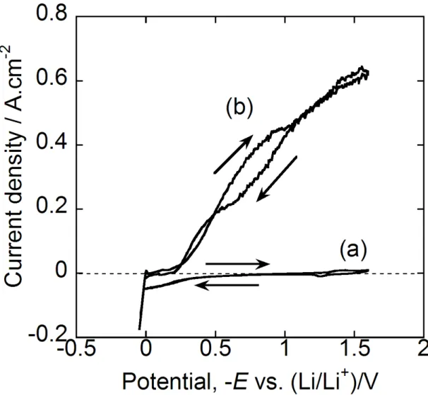
3.1 Electrochemical behavior 69
3.2 Surface structure 71
3.3 Cross-section 73
3.4 XPS analysis 79
3.5 XRD analysis 85
References 88
Chapter 4 Thermodynamic consideration 91
1. Thermodynamic consideration 91
2. Equilibrium electrochemical synthesis 92
3. Conclusions 108
References 109
Chapter 5 Conclusions 111
xv
Appendix Corrosion characteristic of AlN, Y
2O
3, Er
2O
3and
Al
2O
3in FLiNaK for molten salt blanket system 115
1. Introduction 115
2. Experimental 117
2.1 Specimen preparation 117
2.2 Test condition 118
3. Results 120
3.1 Surface observation 120
3.2 Weight change of specimens 127
3.3 Chemical analysis 128
4. Discussion 129
4.1 Thermodynamic stability 129
4.2 Solubility of oxide and nitride in FLiNaK 130
4.3 Corrosion resistance of AlN in FLiNaK 132
4.4 Corrosion of Al2O3, Er2O3 and Y2O3 in FLiNaK 133
5. Conclusion 135
References 136
Publication list 139
xvi
xvii
Figure list
Chapter 1
Figure 1. 1. Trends in rate of energy utilization in the world from 1850 to
2100. 7
Figure 1. 2. Phase diagrams of FLiBe and FLiNaK. 31 Figure 1. 3. Relationship among materials at heat exchanger in molten
salt blanket system. 33
Figure 1. 4. HF behavior in molten FLiBe with dipping beryllium. 34 Figure 1. 5. Schematism of blanket system. 37
Figure 1. 6. Surface modification of structural material by electrochemical
nitriding in fluoride molten salt. 44
Chapter 2
Figure 2. 1. Ellingham diagram of nitrides and oxides. 55 Chapter 3
Figure 3. 1. Experiment setup for electrochemical measurement and
treatment. 63
Figure 3. 2. Time-temperature curves for the electrochemical treatment. 67 Figure 3. 3. Cyclic voltammogram of for 316 SS electrode in fluoride
eutectic salt FLiK. 70
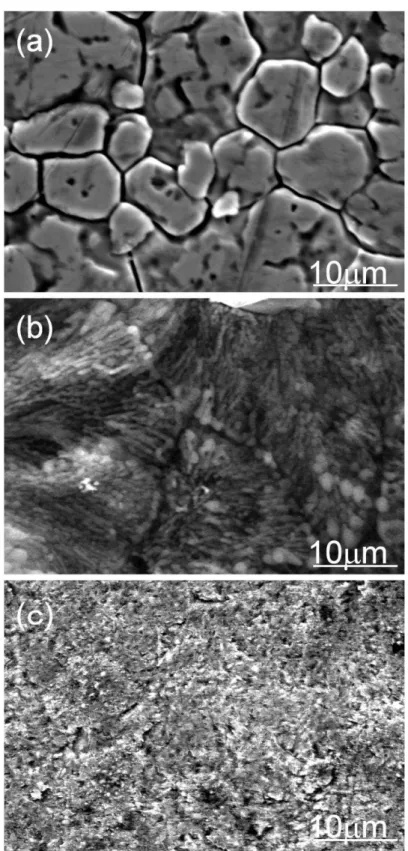
Figure 3. 4. SEM images. 72
Figure 3. 5. Compositional analysis of cross-section of the specimen treated in FLiK including 2mol% of Li3N for 100min by EPMA. 76 Figure 3. 6 Compositional analysis of cross-section of the specimen treated in FLiK by EPMA and metal weight ratio evaluated by EDX. 78 Figure 3. 7. Compositional depth variation obtained by XPS. 80
xviii
Figure 3. 8. XPS spectra of the specimen before and after electrochemical treatment for 100min in FLiK containing Li3N. 82 Figure 3. 9. Separation of chromium 2p peaks in XPS. 84
Figure 3. 10. X-ray diffraction patterns. 87
Figure 3. 11. Phase change from fcc structure to bct structure in nitrogen
introduction. 88
Chapter 4
Figure 4. 1. Deposition potential of nitrides in Fe-Cr-N3- system on the
nitriding of 316 SS. 95
Figure 4. 2. Equilibrium electrochemical synthesis (EES) diagram on
nitriding of 316SS. 97
Figure 4. 3. Potential-pN3- diagram of chromium nitride and iron nitride
in fluoride eutectic salt. 103
Chapter 5 Appendix
Figure A.1 Capsule for immersion test. It consists of SS316 tube and
Swagelok. 119
Figure A.2 Photos of specimens before and after immersion test. 120 Figure A.3. Surface images of specimen by SEM and surface element
analysis by XPS. 122
Figure A.4. Impurity concentrations in Flinak before and after
immersion test. 129
Figure A. 5. Corrosion in AlN-Flinak-316L steel system. 133 Figure A. 6 Corrosion in Al2O3-Flinak-316L steel system. 134
xix
Table list
Chapter 1
Table 1. 1 Generation systems for blankets around 500 C and efficiency. 23 Table 1. 2. Physical properties of FLiBe and FLiNaK. 31 Table 1. 3. Structural material and dimensions for FFHR2 blanket system.
38 Table 1. 4. Tritium inventory evaluation of FLiBe for FFHR. 38 Chapter 2
Chapter 3
Table 3.1 Composition of 316 stainless steel specimen and treated
specimen. 65
Chapter 4
Table 4. 1. Deposition potential of nitrides on 316 stainless steel specimen 96
Table 4. 2. Thermodynamic data at 873K 102
Table 4. 3. Standard potential E / V referred to the Li+/Li couple. 102 Table 4. 4. Change in standard Gibbs free energy at 873K. 105 Chapter 5
Appendix
Table A. 1 Composition of specimens (at%). 118 Table A. 2 Weight Change for immersion test (unit: g/m2). 127 Table A. 3. Impurity composition in Flinak before and after immersion
test. 128
xx
Table A. 4. Gibbs energy for reaction of ceramics material in Flinak at
600C. 130
1
Chapter 1 Introduction
1. Current state on energy issue
1.1 Brief summary in history in energy issue
Our life depends on fossil fuel at the present day. It has been used after at the birth of the industrial revolution in the 18th century. Coal has been using for generating energy. Heat generated by burning it raises steam from water. It was applied for source of power like a steam engine. The steam engine using coal was the first great wave of industrialization based on a truly disruptive technology. Coal remained the dominant fuel until right after the end of World War II (WWII).
After WWII, Industrialization, urbanization and motorization have shaped the modern energy economy which we know in this day. Trend of energy economy is associated with increasing quantities of
2
energy consumption, efficiency of energy use in production and consumption, diversification of sources of energy, and demand for clean and convenient energy at the point of use. The next major transition in energy economy trend came with electricity and the internal combustion engine. Heat from burning fossil fuel began to generate electric power through steam engine. Steam turbine extracts thermal energy from pressurized steam and drive electric power generator. Steam power plant is still leading and prime power sources.
While coal is solid fuel, petroleum oil is liquid fuel. Because of easy handling of oil, coal gave the place as a power source to oil with change of times for transport. Coal remains the principal fuel in power generation. Although coal is gradually being replaced by natural gas and recently by renewable, fissile fuel remains main power source at the present moment. In our country, Japan, electric power of 1 billion kWh is consumed for public power supply industry. Considering combination of energy sources, 65% was occupied by fossil fuel which consists of coal, liquid natural gas and oil. And 70 million automobiles are running consuming gasoline or diesel oil as fuel. These automobiles consume oil
3 of 57 million kilo litters a year in 2004[1].
In addition to being energy resource, oil plays another important role as a resource to produce many kinds of chemicals. Plastics and chemical textiles prepared from oil especially became widely used as a most accessible material in our daily life. Almost all kinds of industrial products are made of them. Oil is indispensable for our modern life with metal and semiconductor material. We depend on oil on almost all aspect in our life.
However, there are also disadvantages for using oil. Emission of carbon dioxide, CO2, to atmosphere became to be forced on as an environment related issue from the end of 20th century. It can be said that CO2 not only causes acid rain but also work as a green house gas. According to the 4th report from Intergovernmental Panel on Climate Change (IPCC), they pointed out that emission of CO2 by consumption of fissile fuel to atmosphere after the industrial revolution involves global warming for several decays. Besides the environmental issue, minable amount of sessile fuel came to a significant and serious issue. Amount of minable fossil fuel is limited. At the end of 2010, amount of minable oil
4
is1383.2 billion tons, that of minable natural gas 187.1 trillion cubic meters and that of minable coal 86.1 billion tons[2].
As an alternative energy resource, atomic energy was developed in the middle of 20 century. Uranium has been used as an energy resource for over half a century. Although it began to be developed with military usage during WWII, minable amount of uranium is estimated as 5.4 million tons at the end of 2009[3]. If nuclear fuel cycle comes to completion using fast breeding reactor (FBR), more energy might be extracted drastically. However, in fact large amount of spent fuel is stored in spent fuel pool next to each reactor. And reprocessing for removing impurities from the spent fuel will produce large amount of plutonium with high level radioactive waste. If using uranium at current consumption rate, it will exacerbate problems on nuclear fuel storage. When operation of nuclear reactors and storage of nuclear fuel is managed, catastrophic disaster, earthquake and tsunami, should be also considered. And bringing out nuclear material to black market related terrorism should be prevented. And all kind of apparatus for nuclear engineering should be also protected from terrorist attacks. The
5
overhead cost for management of nuclear fuel is increasing due to these situations. Development of atomic energy has a close relation to nuclear arms development. Besides technical issues, the development as an energy engineering often causes political issues in the international community.
1.2 Prospective on energy issue
Population and economic growth are the two most driving force behind the demand for energy. Since 1900 world population has more than quadrupled, real income has grown by a factor of 25, and energy consumption by a factor 22.5. In other words, countries which affiliated into Organization for European Economic Cooperation (OEEC) and Organization for Economic Co-operation and Development (OECD) have led the global economic growth. Over the last 20 years, would population has increased by 1.6 billion people, and it will rise by 1.4 billion over the next 20 years. While income growth is trending up, population growth is trending down. However, in the next 20 years global integration will more progress. And low and medium income economies in non OECD
6
countries will grow rapidly. The world’s real income has risen by 87% over the past 20 years. This implies to rise by 100% over the next 20 years. At the global level, the most fundamental relationship in energy economics remains robust, i.e, more people will get more income. This means the production and consumption of energy will rise.
It is often discussed using R/P ratio which is defined as dividing proved reserves by production. Considering R/P ratio of fossil fuels, R/P ratio of minable coal is estimated as 118 years, oil as 46.2 years and gas as 58.6 years at the end of 2010, respectively. Minable crude reserves about these fossil fuels have been revaluated every year. It steadily increases with progress of extractive technology and exploration of new coal field and oil field. However, because explosive economic progress in non OECD countries including China or India will cause upsurge of consumption of fossil fuel, minable year on fossil fuel does not seem to extend drastically. Figure 1. 1 demonstrates trends in rate of energy utilization in the world from 1850 to 2100. This suggests that what kind of energy was used depends on industrial establishment. Besides date, there would be local difference. Coal is also used c and is not outdated
7
energy. And natural gas will be a main energy source. Considering nuclear energy, not for military use, it will be used also for consumer use. From view point of energy security, combination of several kind of energy is eligible to disperse risk in energy issue. Our country, Japan, has imported oil as a main energy source. Increase of energy options means to be more secure in energy issue.
Figure 1. 1. Trends in rate of energy utilization in the world from 1850 to 2100 [4].F = fraction of market penetrated. Prediction on fusion energy was added to the original figure by K. Furukawa[5].
To overcome energy issue, many kinds of energy development are carried out. Fusion engineering is one of them. Energy is generated by fusion reaction due to fusion between light atoms like hydrogen. For example, reaction between deuterium and tritium generates 4He with
8
energy of 3.52MeV and neutron with energy of 14.1MeV. Deuterium accounts for approximately 0.0156% (or on a mass basis: 0.0312%) of all naturally occurring hydrogen in Earth's oceans. Although naturally occurring tritium is extremely rare on earth, it is produced in nuclear reactors by neutron activation of lithium. Ocean water includes lithium of 0.1-0.2 mg/litter. These mean that infinite natural energy resource exists in oceans. Research and development on fusion reactor began in the middle of the 20th century. Although more than half a century have already passed since the commencement of research and development, it will need to take longer development period to realize a commercial reactor.
1.3 Fusion reactor as an energy generator
1.3.1 Brief summary of history in research and development on Fusion reactor
Research and development for fusion reaction as an energy device started in the middle of the 20 century. Sir George Paget Thomson and Moses Blackman in UK obtained the first patent related to a fusion reactor in 1946 and started experiments with pinch concept.
9
Around the same time, Ronald Richter proposed the Huemul Project in Argentina. Although his group announced positive results in 1951, unfortunately, these results were false. The UK pinch programs were greatly expanded and progressed to the ZETA and Sceptre devices. In the US, pinch experiments like those started in the UK started at the Los Alamos National Laboratory. Similar devices were also built in the USSR. At Princeton University, Lyman Spitzer developed a new approach in 1950, which is known as stellarator in this day. And Lawrence Livermore National Laboratory entered the field with their own variation, the magnetic mirror. These three groups have remained the primary developers of fusion research in the US to this day. In time since these early experiments, two new approaches developed that have since come to dominate fusion research. The first one was the tokomak approach developed in USSR, which combined features of the stellarator and pinch to produce a device that dramatically outperformed either. In our country, Japan, K. Uo also proposed Helical Heliotron field for plasma confinement in 1958[ 6 ]. The majority of magnetic fusion research to this day has followed the tokomak approach. In the late
10
1960s the concept of "mechanical" fusion using lasers was developed in the US, and Lawrence Livermore switched their attention from mirrors to lasers. Although more than fifty years have already passed since the fist fusion reaction, applications for energy device are still being developed. It took less than ten years for fission to go from military applications to civilian fission energy production. This is very different in the fusion energy field and accounts for that, unlike the original prospect, control of fusion reaction with technology in the middle of the 20th century has been found to be very difficult over time.
At the end of the 20th century, technical development of superconductivity material allowed us to make coil generating strong magnetic field and is realizing the thermonuclear fusion reactor. And in France, International thermonuclear Experimental Reactor (ITER) is being constructed today in the 21st century. The project is funded and run by seven member entities - the European Union (EU), India, Japan, the People's Republic of China, Russia, South Korea and the United States. ITER is attempting to carry out commencement of operation from 2018 and will be the first fusion reactor which generates electric
11 power.
1.3.2 Requirements on thermal fusion reactor as an energy device
Considering reactor to generate electricity by some fusion reactions in a practical reactor, obtaining large amount of heat energy by the fusion reactions, easy control of the fusion reactions and establishment of continuous fuel supply into the reactor are required for long operation period. The reactions between two deuterium (D-D reactions) and those between deuterium and tritium (D-T reaction) satisfy the mentioned conditions. Deuterium is a naturally occurring isotope of hydrogen and is universally available from water. Considering these reactions, from the view point of fuel supply, the D-D reactions are easier than D-T reaction. Although more difficult to facilitate than the deuterium-tritium reaction, the fusion can be achieved through the reaction of deuterium with itself. This reaction has two branches that
occur with nearly equal probability: H
T D
D 2 3 1
2
n
3He
(1.1)
The first branch produces tritium. Although a D-D reactor will
12
not be completely tritium-free, it does not require an input of tritium and/or lithium. Most of the tritium produced will be burned before leaving the reactor, which reduces the tritium handling required, but also means that more neutrons are produced and that some of these are very energetic. The neutron from the second branch has an energy of only 2.45 MeV, whereas the neutron from the D-T reaction has an energy of 14.1 MeV, resulting in a wider range of isotope production and material damage. Assuming complete tritium burn-up, the reduction in the fraction of fusion energy carried by neutrons is only about 18%. The primary advantage of the D-D reactor is that tritium breeding is not required. This means that the D-D reactor is released from restriction of lithium resources and that neutron spectrum is somewhat softer.
However, due to the critical plasma condition for the D-D reactions, the plasma should be heated over 1000 million K. It is impossible to maintain the heated plasma at the high temperature by existing plasma control technique. From view point of material engineering, there is no thermal resistant material against the heated plasma. Accordingly, because the D-T reaction can cause lower
13
temperature at one order than D-D reaction, development of fusion reactor due to the D-T reaction is attempted to realize it this day.
The D-T reaction is as follows:
n He T
D 3 4
2 . (1.2)
In this reaction, energy of14.1 MeV is generated. The large mass ratio of the hydrogen isotopes makes the separation rather easy compared to the difficult uranium enrichment process. Tritium however occurs naturally in only negligible amounts due to its radioactive half-life of 12.32 years. Consequently, the deuterium-tritium fuel reaction requires the breeding of tritium from lithium using one of the following reactions:
He T Li
n6 3 4 (1.3)
and
n He T Li
n7 3 4 . (1.4)
The reactant neutron is supplied by the D-T fusion reaction shown above, the one that also produces the useful energy. The reaction with 6Li is exothermic, providing a small energy gain for the reactor. The reaction with 7Li is endothermic but does not consume the neutron. At least some
7Li reactions are required to replace the neutrons lost by reactions with other elements.
14
To produce tritium, several systems are proposed. One is Fusion–Fission hybrid system. For example, a combination of molten salt fission reactor and fusion reactor is proposed. In LiF-BeF2 molten salt Including UF4 and/or ThF4, lithium also carries out the nuclear fission reaction simultaneously with the nuclear fission reaction of uranium and/or Lithium also carries out a nuclear fission reaction simultaneously with the nuclear fission reaction of uranium. It is possible to produce tritium with generating electricity by nuclear fission plant simultaneously. From view point of economy, power generating cost seems to be low. In commercial power generation, light water reactor is in practical use in our country. Tritium is also obtainable from heavy water reactor like a CANDU reactor (short for CANada Deuterium Uranium reactor) without any certain target for reaction of tritium production. Development and construction of molten salt reactor or heavy water reactor for the system are in the order of ascending priorities. And almost all country using fission reactor will replace it to fusion reactor. They do not have the plan about fusion-fission hybrid system. In country, tritium production by neutron irradiation to 6Li-Al
15
alloy target is considered. Tritium produced in the target is collected[7]. Another one of tritium production system is nuclear spallation. When protons accelerated to several hundred MeV to several GeV using accelerator are collided to heavy atoms, tritium was produced [8,9]. Tritium is produced in the exclusive plant only for tritium production from lithium. The tritium is transported to independent fusion reactor. And it was burned with deuterium there. Comparing fusion reactor with blanket system for tritium breeding, the fusion reactor can be down sized. The last one introduced in this section is blanket system. Containers filled with lithium or lithium compound, blanket, are installed surrounding reactor core. Lithium is irradiated with neutron generated from the fusion reaction in the reactor core to produce tritium. Fuel cycle is completed in the fusion reactor itself. Because apparatuses for storage and transport of tritium are not needed, a compact system with fuel cycle can be assembled. This system is independent of fission reactor and acceptable in several countries which do not want to construct fission reactor. Because the reactor is upsized to install blanket around the reactor core and tritium permeation barrier is
16
needed, construction cost will increase. Reservation of initial tritium for ignition is also an important issue. The main research and development in the fusion engineering field aim at development of reactor equipped with the blanket system. This work is also for development of equipments in blanket system.
2. Roles and requirements of blanket system for fusion power reactor 2.1 Overview
Fusion energy possesses advantages in safety and energy security. It also provides slightly load to environment. Due to these reasons, it is expected as a prospective backbone energy source. To leverage it as a backbone energy source, it should be supplied in some kind of usable energy form. Blanket plays an important role to transfer from fusion energy to usable energy form for application. In this chapter, roles and requirements of power reactor to be practical use of fusion energy are shown from view points of economics, fuel supply, power generation system, maintenance, radioactive waste, and interaction between wall and plasma[10].
17 2.2 Economics and fuel supply
Practical application of fusion energy requires technology for transformation from fusion energy to usable energy form. In the same time, it should be stably supplied to consumers at reasonable and economic price.
2.2.1 Economics about blanket and fusion energy
Blanket in power reactor plant affects on economics of fusion energy. The affection is derived from many kinds of factor. First of all, cost for manufacturing and mandatory-replacement parts is considered. To reduce it, reasonable blanket was favorable. Due to design compact and high performance blanket with simple structure expensive material such Li-6 condensation, Be and vanadium alloy should be reduced.
Second, thermoelectric conversion rate should be gained. It directly affects on electric output. To obtain high efficiency, blankets using helium cooling or lithium cooling are attractive. However, in this system using intermediate heat exchanger and steam generator in thermal transfer system besides blanket itself, coolant material would
18
affect on construction and maintenance cost.
Third, operation rate should be gained by elongation of life time and simplification of replacement. Considering material which we can use, high energetic neutron load wall material requires frequent replacement of plasma counterwall such as first wall. Deterioration of breeding rate by burning breeding material also require its replacement. Those replacements will reduce utilization rate of the power reactor plant. Because of these reasons, reliable blanket with long life time should be designed. In same time, replace procedures which are done within short term should be developed.
Finally, neutron multiplication factor should be considered. Almost of fusion energy output is transferred to blanket by neutron. Then, neutron multiplication factor affects on its thermal output. It means that it affects on electric power cost. For example, using Be, although the construction rate would be increased, energy multiplication factor would be increased. This means that economics is consequently improved.
19 2.2.2 Tritium procurement and breeding
Tritium breeding is a function which conventional power systems have never possessed. Because abundant deuterium (D) and tritium (T) are used in fusion energy as fuel, the fuel is not unevenly distributed. This means that it is more advantageous in energy security than other energy. Fusion power reactor generates energy by burning D and T. Although it depends on system design, beryllium (Be) also is consumed as neutron multiplier. 1GW class power plant would consume about 105kg/y of D and 370kg/y of T, respectively. Be would be also consumed about 200kg/y. Stable supply is indispensable to complete the fusion power plant. According to stock assessment, D and T will be supplied continuously and stably. However, since Be supply has a quantitative restriction, Be recovery from spent blanket and efficient recycle of Be are required. The system which does not need Be neutron multiplier should be developed in future.
Although T is one of fuel for D-T reaction, in fact, it is defined an intermediate product for the whole system. The blanket in power plant needs enough capability for tritium self sufficiency. For the purpose, net
20
tritium breeding ratio (TBR) should be over 1.07 [11, 12]. However, from the viewpoint of status in development of structural material, uncertain in nuclear data and technology for maintenance, it is formidable task to develop the blanket at present. There is no clear prospect about blanket development.
It will be obtained through development of experimental production such a test blanket module (TBM) for ITER.
Starting fusion power plant needs a large amount of initial load fuel [13]. Supply of T might have decisive influence for introduction of fusion energy to energy market as a commercial power plant. Since T has no demand in general industry, T should be produced just for fusion reactor. To achieve prosperous introduction of fusion power reactor to energy market, the initial reactors might produce initial load T for the next reactors. If T reservation spends long time, the introductory pace for fusion power plant will decelerate.
Starting without initial load T has been also discussed. The introductory pace does not limited by T breeding. This scenario needs TBR over 1.07. The limitation of the introductory pace will be mitigated
21 a little.
2.3 Blanket power generation system 2.3.1 Current status in system design
Electric power generation system for blanket system in fusion power reactor will be designed based on that for conventional nuclear power plant. Fission reactor corresponds to blanket. Fusion power plant will take over facilities such waste disposal and treatment facility, turbine plant facility and electric generating facility from fission power plant. Specific facilities which do not exist in conventional fission power plants should be developed. For example, following facilities and equipments are listed: first wall, breeding blanket, diverter, vacuum vessel, vacuum system, superconductive magnet coil, cooling system, cooling system, high frequency heating device (NBI and RF), tritium recovery system and tritium storage system. Among them, first wall, breeding blanket and tritium storage system needs technological developments. The facilities and equipments for ITER have been already developed in ITER EDA and will be applied to the fusion power reactors
22
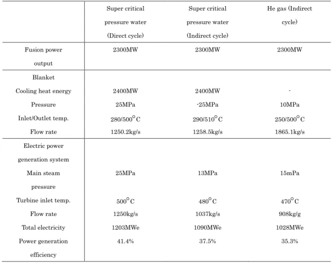
in next generation. At the present stage, the structure of the blanket itself is being developed in universities and institutes associated with nuclear engineering. Several design concepts for blanket have been proposed using different kinds of structural material, coolant, and breeding. On the other hand, if problems for material can be overcome, reheat cycle system, which has been progressed in development for light water nuclear reactor, could be used for fusion reactor. Thermal power generation by supercritical water or hated vapor could be applied to fusion power plant. Considering cooling order (primary cooling system or secondary cooling system), coolant material and temperature for operation should be selected. Table 1. 1 demonstrates comparison among typical generation systems using critical pressure water and He gas cooling blanket. In case of blanket using liquid metal or molten salt including lithium, operation could be possible at higher temperature over 500°C. Steam turbine similar to that for fast breeding reactor (FBR) can be considerable.
23
Table 1. 1. Generation systems for blankets around 500 C and efficiency.
Super critical pressure water
(Direct cycle)
Super critical pressure water (Indirect cycle)
He gas (Indirect cycle)
Fusion power output
2300MW 2300MW 2300MW
Blanket
Cooling heat energy 2400MW 2400MW -
Pressure 25MPa -25MPa 10MPa
Inlet/Outlet temp. 280/500C 290/510C 250/500C
Flow rate 1250.2kg/s 1258.5kg/s 1865.1kg/s
Electric power generation system
Main steam pressure
25MPa 13MPa 15mPa
Turbine inlet temp. 500C 480C 470C
Flow rate 1250kg/s 1037kg/s 908kg/g
Total electricity 1203MWe 1090MWe 1028MWe
Power generation efficiency
41.4% 37.5% 35.3%
2.3.2 Requirements for electric power reactor
Assuming fusion power plant as an electric power generator, it should adapt to electric grid consisting of several kinds of power sources.
24
Then, following factors should be considered: economics based on electric power demand in future, competitive strength against other electric power source and adjustability for load following operation.
2.3.3 Maintenance
There are typical concepts in maintenance: hard time (HT), on condition (OC) and condition monitoring (CM). HT: from viewpoint of planning maintenance, disassembly, inspection, replacement and fix are done for each part at regular intervals. OC: only function inspection without disassembly is done for a facility. If it passes the inspection, it is used until the next inspection. CM: monitoring function of a facility at all times, when any trouble is found at a facility, it is checked and fixed. In initial fusion power plant, HT maintenance will be done. After accumulation of experience and knowledge, OC maintenance and CM maintenance will be done. However, it is predicted that radioactive dust and tritium will exist extensively inside fusion power plant. This affects on operating efficiency, simplification and shortening on maintenance. From viewpoint of economics also, considering operating efficiency,
25
simplification and shortening on maintenance, the plant should be designed.
Diverter and first wall blanket will be exposed to particle load and heat load. Because these facilities are used under the harshest condition, maintenance and replacement are needed at regular intervals [14,15]. Overcoming cumbersome related with maintenance, concepts such liquid free surface diverter and gas diverter are also proposed [16].
In general, maintenance scenario depends on reactor type and its operation scenario. For example, utilization rate over 80% for first wall in case of DEMO reactor can be achieved by replacement of blanket module including first wall every 3 years based on HT maintenance [17]. To extend maintenance interval, SiC/SiC hybrid material and vanadium alloy have been developed as robust materials against neutron damage. However, if facilities were made by those materials, it seems to be difficult to use those facilities over 30 years like a pressure vessel in fission power plant.
Considering superconducting magnet, due to its high construction cost and difficulty on replacement, it will be used for reactor lifetime in
26
common operation scenario. However, it will need maintenance. Segmentization and replacement of superconducting magnet are discussed [18, 19].
2.3.4 Waste
In replacement of facilities for maintenance or deconstruction of reactor, radioactive structural material and adherent tritium can cause a problem as nuclear waste. Breeding material including lithium and neutron multiplying material including beryllium should be recycled from viewpoint of effective utilization of resource. After decontamination and volume reduction, considering quantity and kind of nuclear specie, the waste will be disposed. This is a process similar to that in conventional nuclear engineering.
In case of waste from fusion reactor, radioactive waste will cause by maintenance and replacement of facilities which face to plasma or be contaminated by tritium. First wall, blanket, diverter and equipments with those correspond to those. When radiation level of the waste is evaluated, those will be low level radiation waste. Those will not need
27
deep geological disposal. Amount of the waste depends on material selection. It is different from high level radiation disposal from nuclear fuel in conventional fission nuclear engineering. The waste from fusion power plant is low level radiation waste including gamma or beta waste. For fusion power plant, low active ferritic steel was developed. However, because it includes tungsten which can transform to beta or gamma radioactive nuclear species, amount of low level radiation waste will increase by utilization of the low active ferritic steel. In case of using low radioactive material like a SiC/SiC hybrid material, amount of the waste can be reduced. In any case, waste disposal should be evaluated based on economics from feature of wastes.
3. Molten salt blanket system 3.1 FLiBe
Molten salt was considered in development of fast breeding reactor and liquid fuel reactor in the 1940. One of the molten salts for the system used in the system is FLiBe (eutectic mixture of LiF and BeF2). Many data was collected from the development of the system. Table 1. 2
28
demonstrates physical property of FLiBe [20]. Figure 1.2 demonstrates phase diagram of FLiBe. In Oak Ridge National Laboratory (ORNL) in the 1950, molten salt reactor (MSR) was operated for 5 years [21]. Based on the success in MSR, concept of helium cooling molten salt blanket was proposed at Princeton University in the 1970 [22]. Its features follow. (1)Low tritium solubility: it is lower at the 8th order than that of metal lithium. It is easy to recovery tritium it means that tritium inventory can be reduced to gram order in whole flow loop like a blanket system. (2)Leak security by low chemical activity: because it does not react water or air, the system including molten salt is protected against fire in leakage from flow loop. (3)High temperature operation at low vapor pressure: Because of low vapor pressure (4mPa at 500 C), operation at atmospheric pressure can be constructed. (4)low electric conductivity: because of low electric conductivity (1 ohm.cm), MHD pressure loss can be avoided. (5) specific heat (1 cal/cc.degree): because it is at the same level as that of water, self cooling system can be constructed. Although system using molten salt has high safety, several disadvantages are pointed out. Assessment by US department of energy
29
(DOE) [ 23 ] required database about compatibility with structural material, high heat transfer as a Prandtl number liquid and tritium permeability in system operation at high temperature. In national institute for fusion science (NIFS) in Japan, blanket system for FFHR design (large helical device type reactor) has been developed since 1993 [24]. With this as a turning point, FLiBe was reconsidered in APEX in US [25]. JUPITER-II by Japan and US also started in 2001. These activities are completing the database required by above DOE assessment [26]. Achievements from these activities follow: (1) Redox by beryllium against corrosive HF in fluoride salt, (2) promotion of heat transfer at low flow rate and (3) development of large scale numerical simulation code.
3.2 FLiNaK
FLiNaK is also eutectic fluoride salt (LiF-NaF-KF). Because it does not include beryllium, it is often used in experiments for molten fluoride salt. FLiNaK salt was also researched during the late 1950s by ORNL as potential candidate for a coolant in MSR because of its low melting point, its high heat capacity, and its chemical stability at high temperatures.
30
Resultingly, FLiBe was employed as the solvent salt for MSR due to a more desirable nuclear cross section. FLiNaK still gathers interest as an intermediate coolant for a high-temperature MSR where it could transfer heat without being in the presence of the fuel [27].
In the immerse test carried out prior to development of electrochemical nitriding for this dissertation, FLiNaK was used as described in appendix. Table 1.2 also demonstrates its physical properties and Figure 1.2 demonstrates the phase diagram of FLiNaK. In the electrochemical nitriding described in this dissertation work, FLiK which is eutectic salt (LiF-KF) was used. These melting points are indicated in the diagram.
31
Salt Teperateure Density Viscosity
Kinetic coefficence of
viscosity
Specific heat at constant
pressure
Thermal conductivity
Thermal diffusivity
Electric resistivity
Prandtl number T K(C) r Kg/m3 h mPa.s n mm2/s cp kJ/(m.K) l W/(m.K) a mm2/s re Kg/m3 Pr
FLiBe 750(477) 2014 2.39 1.00 0.21 7.13×10⁵
(LiF-BeF2 :66-34mol%) 800(527) 1993 7.50 3.76 2.39 1.00 0.21 5.88×10⁵ 17.90
Melting point Tm = 731K(458°C) 900(627) 1951 2.70 1.38 2.38 1.00 0.22 4.34×10⁵ 6.43
1000(727) 1909 1.97 1.03 2.38 1.00 0.22 3.42×10⁵ 4.69
1100(827) 1867 1.88 1.01 2.37 1.00 0.23 2.86×10⁵ 4.46
FLiNaK 750(477) 2182 1.88 1.20 0.29 9.17×10⁵
(LiF-NaF-KF: 46.5-11.5-42.0mol%) 800(527) 2146 1.88 1.20 0.30 8.33×10⁵
Melting point Tm = 731K(454°C) 900(627) 2073 4.10 2.00 1.88 1.20 0.31 7.09×10⁵ 6.40
1000(727) 2000 2.60 1.30 1.88 1.20 0.32 6.17×10⁵ 4.10
1100(827) 1927 1.80 0.93 1.88 1.20 0.33 5.43×10⁵ 2.80
Table 1.2 Physical properties of FLiBe and FLiNaK
Figure 1.2. Phase diagrams of FLiBe and FLiNaK. (a) System of LiF-NaF-BeF2, (b) System of LiF-NaF-KF.
(a) (b)
FLiK FLiNaK
32 3.3 Compatibility
When molten salt such a fluoride salt is used as a coolant media, we should consider compatibility of structural material with it. Figure 1. 3 schematically demonstrates a relationship among the materials in the system. In addition to that, the blanket system will be operated under harsh condition of high temperature over 500C and partially in neutron irradiation condition. Life span over 20-30 years will be required for the practical system in fusion reactors. The firm allowed penetration rate, ie. reduction rate in thickness by corrosion, have to be decided. However, it has not been decided yet. Because the practical deign of the system has not been completed, it is difficult to decide it at the present stage. Even then, the criterion, penetration rate p, by R.W. Revie and H.H. Uhlig would provide us a useful guideline [28]:
(A). p < 0.15 mm/year — Metals in this category have good corrosion resistance to the extent that they are suitable for critical parts, for example, valve seats, pump shafts and impellors, springs.
(B). p = 0.15 to 1.5 mm/year — Metals in this group are satisfactory if a
![Figure 1. 1. Trends in rate of energy utilization in the world from 1850 to 2100 [4].F = fraction of market penetrated](https://thumb-ap.123doks.com/thumbv2/123deta/6159085.103850/29.892.170.781.546.804/figure-trends-energy-utilization-world-fraction-market-penetrated.webp)