Synthesis and Electrochemical Studies of
Mesoporous Carbon Nano-Dendrites
Doctoral Dissertation
by
Shigenori Numao
Department of Structural Molecular Science
School of Physical Sciences
The Graduate University for Advanced Studies
2009
Contents
Contents……….………..i
Abstracts……….………v
Chapter 1 General Introduction 1.1 Preface……….1
1.2 Supercapacitor……….4
1.3 Lithium ion battery………..7
1.4 Direct methanol fuel cell………...11
1.5 Scope for chapters……….15
1.6 Reference for chapter ………...18
Chapter 2 Synthesis and characterization of Chapter 2 mesoporous carbon nano-dendrites (MCNDs) 2.1 Introduction………...23
2.2 Experimental 2.2.1 Synthesis of MCNDs………25
2.2.2 Characterization of MCNDs………...27
2.3 Result and Discussion 2.3.1 Ag2C2 dendrite……….28
2.3.2 MCND structure………..30
2.3.3 Spectroscopic characterization………...34
2.3.4 Porosity characterization………....39
2.4 Conclusion of this chapter……….43
2.5 Reference for chapter 2……….44
Chapter 3 Electrochemical study of MCND electrodes Chapter 2 for supercapacitor application
3.1 Introduction………...47 3.2 Experimental
3.2.1 Fabrication of MCND electrodes………49 3.2.2 Evaluation of MCND electrodes………..51 3.3 Result and Discussion
3.3.1 Cyclic voltammetry……….53 3.3.2 Constant current charge-discharge measurement…………..55 3.4 Conclusion of this chapter……….59 3.5 Reference for chapter 3……….60
Chapter 4 Synthesis and characterization of Sn/MCND composites Chapter 3 as anode materials for Lithium-ion batteries
4.1 Introduction………...61 4.2 Experimental
4.2.1 Synthesis of Sn/MCND composites……….64 4.2.2 Characterization of Sn/MCND composites……….65 4.3 Result and Discussion
4.3.1 Structure of Sn/MCND composites……….67 4.3.2 Electrochemical properties of Sn/MCND composites……….72 4.4 Conclusion of this chapter……….75 4.5 Reference for chapter 4……….76
Chapter 5 Synthesis and characterization of Pt/MCND catalysts Chapter 3 toward methanol oxidation
5.1 Introduction………...79 5.2 Experimental
5.2.1 Synthesis of Pt/MCND catalysts……….81 5.2.2 Characterization of Pt/MCND catalysts……….82 5.3 Result and Discussion
5.3.1 Structure of Pt/MCND catalysts……….84
5.3.2 Electrochemical active surface area of Pt/MCND catalysts...90
5.3.3 Electrochemical activity for methanol oxidation of Pt/MCND catalysts………..94
5.4 Conclusion of this chapter……….97
5.5 Reference for chapter 5……….98
Chapter 6 Conclusion………...99
Acknowledgment………101
Abstract
Due to the high electronic conductivity and variety of forms, various carbon nanomaterials have been developed in recent years. In particular, porous carbon materials and graphitic carbon materials are very promising as electrode materials in supercapacitors, lithium ion batteries, and fuel cells. Recent demands for electrode materials are oriented toward the development of new porous carbon materials with high conductance both for the electron and ion transportations. However, it has been extremely difficult to combine the properties of porous structures and graphitic ones.
We have synthesized silver acetylide (Ag2C2 : Ag−C≡C−Ag) with 3D-interconnected frameworks and converted the acetylide to a new carbon material, mesoporous carbon nano-dendrites (MCNDs) with ultra-thin graphitic structure. MCNDs are synthesized by controlling the highly exothermic segregation reaction of silver acetylyde into carbon with porous structure and silver-vapor. The dendroide acetylides were quickly warmed to 250 °C emitting a brilliant flash of raddish orange light with a thunderous sound indicative of the sudden jump of the local temperature to higher than 2000 °C. The sudden heating boils off the silver from the main body, leaving 3D-interconnected carbon frameworks, the MCNDs.
Raman spectra of MCNDs clearly indicate that carbon frameworks consist of mainly graphitic structure of 1-3 layers. SEM and TEM images as well as EELS spectra show that the main body with ∼100 nm radii branches every 100-150 nm and are composed of cells with ultra-thin graphitic walls. The BET (Brunauer-Emmett-Teller) surface area of MCNDs was estimated to be 1324-1996 m2/g from the nitrogen adsorption and desorption isotherm at 77 K, and the adsorption-desorption curves indicate the presence of micropores (pore size: <2 nm) and mesopores (2-50 nm) with a continuous size distribution up to 10-20 nm. These results show that the MCND combines porous structures with graphitic ones.
One of the most suitable applications of MCNDs is to the supercapacitor electrodes. In this case, the high fluidity of solvent phase is also demanded as well as large surface area. The dendritic structure and the presence of mesopores on the surface area of MCNDs can be well suited for these requirements. In order to examine the electrochemical properties of MCNDs as supercapacitors electrodes, the author assembled Sandwich-type capacitors on a platinum current collector with two carbon electrode sheets consisting mainly of MCND, and polytetrafluoroethylene (PTFE) porous separator were assembled. Cyclic voltammetry of a supercapacitor with MCND electrodes showed good rectangular curves, even at a scanning rate of 300 mV/s and peak current density higher than
10 A/g, suggesting applicability for high current and high-speed charge-discharge capacitors electrodes.
The mesopore on the surface area of MCNDs are also available as impregnate sites of catalyst metals and lithium storage metals. We successfully impregnated tin(Sn) and platinum(Pt) metals in the mesopores of MCND through the adsorption of SnCl2 or H2[PtCl6]·(H2O)6, and the reduction with hydrogen gas.
Sn nanoparticles with an average size of 10 nm were prepared in the pores of MCNDs by chemical reduction of SnCl2 with hydrogen gas for anode materials of lithium ion butteries. The nanoparticles grow with increasing reduction temperature and some pores were occupied with Sn almost entirely. One of the major problems to prevent the practical use of Sn solid single electrodes is poor cycleability due to the large volume changes during lithium alloying and dealloying. However, Sn/MCND composites exhibit significantly enhanced cycling performance for lithium storage. When used as a lithium ion battery, we find that a first discharge capacity of 646 mAh/g and the capacity retain a value of 481mAh/g can be obtained after 50 charge and discharge cycles. This improved cycling performance of the Sn/MCND composite could be attributed to its low-density feature caused by dendritic structure of MCND, which has sizable space for the large volume changes during lithium alloying and dealloying.
Highly dispersed Pt nanoparticles (Ca. 3 nm) in pores of MCND were also easily prepared through the sonochemical process of a solution of H2[PtCl6]·(H2O)6 with MCND. This Pt/MCND composite can be used as an electrode of the direct methanol fuel cell (DMFC) for electrochemical oxidation of methanol fuel. We also prepared Pt/AC (AC : high grade activated carbon, Kuraray YP-17) composites for comparison of electrochemical performance. These Pt/MCND and Pt/AC composites were analysed by TEM observation, X-ray diffraction (XRD) and Thermo Gravimetric Analysis (TGA). These structural analyses show that the average size and quantity of Pt particles on the surface of carbon matrix are very similar to each other. The electrochemical active surface areas and methanol electro-oxidation properties of these catalysts were investigated by cyclic voltammetry. As a result, the Pt/MCND composites indicated higher electrochemical activities than that of Pt/AC composites. The electrochemically active surface area is estimated from the CV curve of the Pt/MCND electrode in 0.5 mol/L H2SO4 solution to be 62.1 m2/g. It is 1.3 times as large as that of the Pt/AC electrode. The excellent performance of the Pt/MCND composite could be attributed to the dendritic structure and the graphitic structure of MCND, which has sizable space for the high fluidity of the solvent and gases for efficient catalytic reaction.
Chapter 1
General introduction
1.1 Preface
Evolving of materials science is an inseparable part of someone's affluent life. For example, the industrial revolution produced by the creation of good-quality steel in the 18th century. Then, from a point of view of materials science, semiconductor materials such as silicon, germanium and gallium nitride etc. could be the most advanced materials in the 20th century. And now, carbon materials with nanoscale microstructure have been counted on as the materials for future industries with highly growing potential. In fact, carbon materials used in a wide sphere in modern society, for example, coated layers (diamond like carbon) of razor, secondary cell electrodes (graphite and activated carbon) and frameworks of aircrafts (carbon fiber) etc. Excellent behaviors of carbon materials such as electric conductivity, thermal conductivity, chemical stability, cost economy, and environmental acceptability have brought a lot of benefit in our life. The variety of uses of carbon originates from three different types of chemical-bonding states: to sp3-, sp2-, and sp-hybridization of their valence orbitals. Thus, the sp3-type of hybridization corresponds to a spatial (3D-)
(2D-) network. Finally, the sp-type of hybridization corresponds to a linear (lD-) chain of carbon. These are well known by the name of diamond, graphite and carbine, respectively[1].
In 1985, R. Curl, H. Kroto, and R. Smalley et al. discovered a new allotrope of carbon, which is named fullerene (C60)[2]. Then, S. Iijima discovered a carbon nanotube in deposited materials on arc-burned graphite rods in 1991[3]. These discoveries of new carbon-allotropes have made a landmark breakthrough in constructing nanostructures by carbon atoms. Since then, a large number of new carbon materials with unique structure have reported, and there has been considerable interest in their unique chemistry and technological applications. Among the various shapes of carbon materials, graphene-based or graphitic materials and porous carbons have been attracted significant attention as electrode materials for use in energy storage applications because of their superior electric conductivity and high surface-area, respectively. In fact, popular supercapacitor electrodes are composed of activated carbon with porous structures[4-6]. The most common electrode materials for the anode of the lithium ion battery is graphite with layered structure of graphenes[7-9]. Carbon nanotubes with graphitic structures and activated carbon fibers with porous structures etc. are used to the excellent catalyst-support materials for the fuel cell electrode[10-14]. Since much high quality electrodes are recently getting increasingly important as
electric vehicles (EVs) and uninterruptible power supply (UPS) for industrial establishments etc., many electrode materials with carbon, metals, and metal oxides have been proposed for this demands in each device.
1.2 Supercapacitor
Supercapacitor is widely used in high density power supply such as UPS, and memory backup systems for notebooks and mobile-phones etc.[15] The electric energy storage process of supercapacitors involves no chemical change, and we use only the physisorption of ions to the electrodes for the charge and discharge process (see Fig. 1.1). This causes electrical double layers on the surface of electrodes. Since the capacitance is proportional to the surface area of the electrode material, electrode materials with higher surface areas have been demanded. Consequently, although they can not store as much energy as the batteries with chemical reaction, supercapacitors possess advantages such as high power efficiency, longer cycle life, high reversibility, and faster charge capability during few seconds[15-16]. In supercapacitors, microstructure of the electrodes materials is a very important factor for their performance. Various shapes of carbon materials, transition metal oxides, and conducting polymers have been investigated as supercapacitor electrodes. Among them, transition metal oxides and conducting polymers have been shown to deliver higher specific capacitances than carbon materials, since they store charges through both double-layer and redox capacitive mechanisms. In particular, RuO2 and IrO2 were found to be promising materials for a high power and high energy density electrochemical capacitors[17-18]. However, the high cost and toxic nature of hydrous ruthenium
oxides make this material unsuitable for practical applications. In contrast, use of conducting polymers is a matter of interest for its low cost, environmental acceptability, and ease of synthesis [19-20]. Unfortunately, the electrochemically deposited polymer electrode induces substantial electric resistivity[21]. Thus, a great interest has been focused on the application of porous carbons as supercapacitor electrodes, because of their chemical stability, low cost, and ultimate strength values. As a most commonly used electrode material for the supercapacitor, some activated carbon powders are good candidates because of their high specific surface area.
Kierzek et al. prepared various activated carbons with the treatment by potassium hydroxide (KOH) and used as supercapacitor electrodes[22]. The Brunauer-Emmett-Teller (BET) surface areas of these activated carbons were as large as 1900 ∼ 2660 m2/g, and the largest capacitance value was over 300 F/g. This approach was effective for producing of microporous activated carbons with the extremely high surface area. However, a problem of this approach is the complex microstructures of the porous carbons which encumber smooth diffusion of ions to innermost regions of the electrode for large capacitance, and it causes the high internal resistance during high power operation.
Figure 1.1 Schematic illustration of the single-cell supercapacitor.
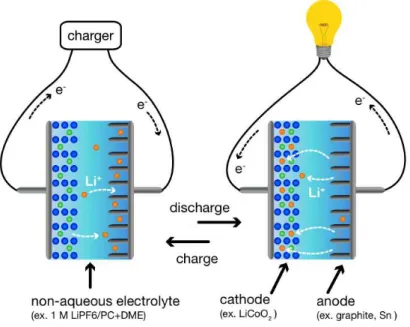
1.3 Lithium ion battery
Lithium ion batteries are currently widely used as a rechargeable battery for the mobile device because of their large energy density. High energy density of this battery is caused by chemical reactions of lithium ions with anode and cathode materials[23-24]. Commercial cells have been consisted by graphite anode, lithium metal (cobalt and nickel etc.) oxides cathode, and a liquid non-aqueous electrolyte[25] (see Fig. 1.2). The performance of lithium ion batteries is highly depended on the choice of materials[26]. In particular, the graphite anode materials affect very much on the device performance. Chemical reactions in the graphite anode are insertion and extraction processes of lithium ions to graphite layers. The degradation of commercially available lithium-ion batteries is linked to the volume changes in the anode materials in these processes. So the maximum theoretical specific capacity of a graphite anode is 372 mAh/g corresponds to the lithium insertion in graphite (LiC6). The graphite electrode maintains a large capacity in long cycles of charge and discharge processes because of its layered structure[24-27]. Consequently, the graphite has been used to anode of lithium ion batteries as the best electrode material[28]. However, the specific capacity of graphite is still not enough to the practical use for EV. Therefore, the demand for alternative anode materials with a higher capacity is now increasing[29].
Figure 1.2 Schematic illustration of the rechargeable lithium-ion battery
Various studies have been carried out on metal-based materials because of their high theoretical capacities[30]. In particular, Tin(Sn)-based anode materials for the lithium ion battery are expected as promising materials alternative to the graphite anodes[31-33]. The theoretical capacity of tin is 992 mAh/g, which is considerably higher than that of the conventional graphite: more than two times of that of the graphite. However, the high capacity is never realized in practice because of capacity fading due to drastic volume changes during the lithium alloying[34-35].
In 1997, Y. Idota et al. developed an amorphous tin oxide-based composite as an alternative anode material for lithium ion batteries with high reversible capacity and good cycleability[36]. This tin oxide-based amorphous composite contains SnO as the active materials for lithium insertion. In the first charge process, SnO regions are reduced with lithium and formed Sn nanopowder with LiO2 matrix. After the second cycle, Sn nanopowders are dispersed in glass-matrix and reacts with lithium reversibly. In this material, grass-matrix regions function as a buffer of the volume changes of Sn nonopowder, moreover that hinder the aggregation of Sn nanopowders in charge-discharge processes. So it has large reversible capacity and good cycleability compared with the electrode composed by pure SnO powder.
Since this report was published, many concepts have been proposed to achieve a new tin based materials mainly composed of metallic tin with high specific capacity as well as good cycle performance[37-40]. In particular, the tin/carbon composite was found to be a promising material for a high capacity and a long cycle life, because the carbon matrix has excellent chemical atability and electric conductivity. Porous structures of activated carbons function as an impregnate site for tin nanoparticles. Moreover they prevent tin nanoparticles from aggregation[41-44]. So various carbon matrices have been proposed for the tin/carbon composite. L. Balan et al. succeeded in preparing tin/graphite composite by reduction of SnCl2 and/or SnCl4 in organic medium[41-42]. A recent report on sonochemical process of a solution of tin chloride with mesoporous carbons presents a new way of preparing the tin/mesoporous-carbon composite for the application as an anode material for a lithium ion battery[44]. However, their practical use is avoided, because, despite their composite have good cycleability, the practical capacities of these composites are at a level of 400 mAh/g.
1.4 Direct methanol fuel cell
The direct methanol fuel cells (DMFCs) have emerged as a promising power source for portable applications such as mobile phones and notebooks etc.[45-47] The main advantage of using methanol as fuel is the ease of transport and storage. DMFCs produce electric power from the oxidation reaction of methanol fuels employing a catalytic process[48]. So it is not necessary to charge. The DMFC has been developed based on two porous electrocatalytic electrodes and a proton-exchange membrane electrolyte. A schematic diagram of a DMFC is shown in Fig. 1.3. At the anode side, protons and electrons are separated from methanol by catalysis:
CH3OH + H2O → CO2 +6H+ + 6e-
The separated protons are transported through the proton exchange membrane (PEM) and the electrons travel through the external circuit from the anode to the cathode. At the cathode side, protons and electrons react with oxygen in a reduction reaction:
6H+ + 6e- + 3/2 O2 → 3H2O
Figure 1.3 Schematic illustration of the electrical generating mechanism in the direct methanol fuel cell.
Among the alcohol fuels, methanol has the lowest weight and the smallest volume and it is most easily oxidized. Thus it has the advantage of a high specific energy density. However, the practical use of DMFC has been restricted because of its technical limitations such as the slow oxidation kinetics of methanol and the reactant crossover from the anode to the cathode.
Platinum group metals or alloys are commonly adopted as the most promising catalyst materials for the methanol oxidation reaction[46-47, 49]. These catalysts have been usually provided as composites in which Pt nanoparticles are deposited on supportting materials. Among Pt support materials, carbon materials have been widely investigated because of its unique structures and varied forms[50-54]. For instance, the porous carbon materials with high surface area are well suited for high dispersion of Pt nanoparticles[55-57]. The graphitic carbon materials with excellent electric conductivity, such as carbon nanotubes and carbon fibers exhibit wide electrical resistances for electron transport during electrochemical reactions[7-14, 58-60]. As a result, these Pt supported carbons catalyst exhibited high catalytic activities. However, it is very difficult to combine these characteristics for both a high surface area and excellent electric conductivity.
K. W. Park et al. prepared that carbon nanocoils (CNCs) with variable
surface areas and crystallinity for the use as the catalysts support of DMFC electrodes[61]. Electrochemical analysis has shown that CNCs with good crystalline structure exhibit better performance than conventional carbon black (Vulcan XC-72) for oxidation reaction of methanol. This result shows that the performance of the catalysts is strongly dependent on the crystalline of carbon support materials. However, the surface areas of CNCs are not so larger than those of conventional carbon black materials. Preparations of novel porous carbon materials with graphitic structure have been a subject of considerable investigation for DMFC electrode application.
1.5 Scope for chapters
The purpose of this study is to create the novel porous carbon materials with graphitic structure as electrode materials for energy storage and electric power source. This dissertation is organized as follows.
Chapter 2 describes preparation and characterization of the novel porous carbon materials: mosoporous carbon nano-dendrites (MCNDs) with ultra-thin graphitic walls. MCNDs are synthesized by controlling the highly exothermic segregation reaction of silver acetylide into porous carbon and silver vapor. Scanning electron microscope (SEM) and transmission electron microscope (TEM) observations are applied to structural analysis of MCND. These microscope observations were indicative of 3D interconnected frameworks with graphitic structures. Raman scattering spectra of MCND indicate that it is composed of graphitic structure of 1-3 graphene layers. Porous structures of MCND are examined by the N2 adsorption and desorption isotherms at 77 K. The author also argues about the mechanism of producing porous and graphitic structures of MCND.
Chapter 3 describes the assembling of two-electrode supercapacitors with MCND electrodes and its electro chemical performance in comparison with other
porous carbon materials. Electrochemical characteristics of MCND electrodes are obtained by galvanostatic charge/discharge and cyclic voltanmetry. The results of these measurements demonstrate extremely superior ion response of MCND to other carbon materials.
Chapter 4 describes the fabrication of the Sn/MCND composite by direct reduction of SnCl2 with hydrogen gases. Excellent reversible lithium storage properties of the electrode are also described. Structural analyses are carried out by TEM observations and X-ray diffraction (XRD) measurements. The specific capacity and cycling stability of this composite were evaluated by galvanostatic charge and discharge curves. From the cycle number dependence of the lithium storage capacitance, the most suited impregnation process of Sn nanoparticles to MCND is discussed.
Chapter 5 describes the preparation of the Pt/MCND catalyst by hydrogen gases reduction of hexachloroplatinic acid in presence of MCNDs and their performance as the electro chemical catalysts. The electrochemical active surface areas and methanol electro-oxidation properties were evaluated by cyclic voltammetry. Amount of Pt metals loaded in this catalyst was analyzed by thermo gravimetric analysis (TGA). TEM observations and XRD measurements were used for structural analyses of these composites. Results of this study show that
the performance of the catalysts is strongly dependent on the structure of supporting carbon materials.
References for chapter 1
[1] R. B. Heimann, S. E. Evsvukov and Y. Koga, carbon, 35, 1654, (1997). [2] H. W. Kroto, J. R. Heath, S. C. O'Brien, R. F. Curl and R. E. Smalley, Nature, 318, 162, (1985).
[3] S. Iijima, Nature, 354, 56, (1991).
[4] D. Qu and H. Shi, Journal of Power Sources, 74, 99, (1998). [5] H. Shi, Electrochimica Acta, 41, 1633, (1996).
[6] J. Gamby, P. L. Taberna, P. Simon, J. F. Fauvarque and M. Chesneau, Journal of Power Sources, 101, 109, (2001).
[7] J.R. Dahn, A.K. Sleigh, Hang Shi, J.N. Reimers, Q. Zhong and B.M. Way, Electrochimica Acta, 38, 1179, (1993).
[8] K. Sawai, Y. Iwakoshi and T. Ohzuku, Solid State Ionics, 69, 273, (1994). [9] O. Yamamoto, N. Imanishi, Y. Takeda and H. Kashiwagi,
Journal of Power Sources, 54, 72, (1995).
[10] G. Che, B. B. Lakshmi, E. R. Fisher and C. R. Martin, Nature, 393, 346, (1998).
[11] G. Che, B. B. Lakshmi, C.s R. Martin, and E. R. Fisher, Langmuir, 15, 750, (1999).
[12] E. S. Steigerwalt, G. A. Deluga, D. E. Cliffel, and C. M. Lukehart, The Journal of Physical Chemistry B, 105, 8097, (2001).
[13] K. Lee, J. Zhang, H. Wang and D. P. Wilkinson, Journal of Applied Electrochemistry, 36, 1572, (2006).
[14] H. X. Huang, S. X. Chen, and Chan’e Yuan, Journal of Power Sources, 175, 166, (2008).
[15] R. Kötz and M. Carlen, Electrochimica Acta, 45, 2483, (2000). [16] G. Lota, T. A. Centeno, E. Frackowiak and F. Stoeckli, Electrochimica Acta, 53, 2210, (2008)
[17] R. Kötz and S. Stucki, Electrochimica Acta, 31, 1311, (1986). [18] S. Ardizzone, G. Fregonara and S. Trasatti,
Electrochimica Acta, 35, 263, (1990).
[19] C. Arbizzani, M. Mastragostino and L. Meneghello, Electrochimica Acta, 41, 21, (1996).
[20] M. Mastragostino, C. Arbizzani and F. Soavi, Solid State Ionics, 148, 493, (2002).
[21] Y. K. Zhou, B. l. He, W. j. Zhou, J. Huang, X. h. Li, B. Wu and H. l. Li, Electrochimica Acta, 49, 257, (2004).
[22] K. Kierzek, E. Frackowiak, G. Lota, G. Gryglewicz and J. Machnikowski, Electrochimica Acta, 49, 515, (2004).
[23] D. W. Murphy and P. A. Christian, Science, 205, 651, (1979). [24] J. M. Tarascon and M. Armand, Nature, 414, 359, (2001). [25] K. Ozawa, Solid State Ionics, 69, 212, (1994).
[26] M. Winter, J. O. Besenhard, M. E. Spahr and P. Novák, Advanced Materials, 10, 725, (1998).
[27] J. M. Tarascon and D. Guyomard, Electrochimica Acta, 38, 1221, (1993). [28] M. Endo, C. Kim, K. Nishimura, T. Fujino and K. Miyashita,
Carbon, 38, 183, (2000).
[29] B. Scrosati, Nature, 373, 557, (1995).
[30] H. Li, X. Huang and L. Chen, Solid State Ionics, 123, 189, (1999).
[31] J. Yang, M. Winter and J. O. Besenhard, Solid State Ionics, 90, 281, (1996). [32] J.O. Besenhard, J. Yang and M. Winter,
Journal of Power Sources, 68, 87, (1997). [33] A. H. Whitehead, J. M. Elliott and J. R. Owen, Journal of Power Sources, 81-82, 33, (1999).
[34] M. Winter and J. O. Besenhard, Electrochimica Acta, 45, 31, (1999). [35] H. Li, L. Shi, Q. Wang, L. Chen and X. Huang,
Solid State Ionics, 148, 247, (2002).
[36] Y. Idota, T. Kubota, A. Matsufuji, Y. Maekawa, and T. Miyasaka, Science, 30, 1395, (1997).
[37] K. D. Kepler, J. T. Vaughey and M. M. Thackeray, Journal of Power Sources, 81, 383, (1999).
[38] J. Wolfenstine, S. Campos, D. Foster, J. Read and W. K. Behl, Journal of Power Sources, 109, 230, (2002).
[39] M. Behm and J. T. S. Irvine, Electrochimica Acta, 47, 1727, (2002). [40] K. T. Lee, Y. S. Jung, and S. M. Oh,
Journal of the American Chemical Society, 125, 5652, (2003). [41] L. Balan, R. Schneider, J. Ghanbaja, P. Willmann and D. Billaud, Electrochimica Acta, 51, 3385, (2006).
[42] L. Balan, R. Schneider, P. Willmann and D. Billaud, Journal of Power Sources, 161, 587, (2006).
[43] I. Grigoriants, A. Soffer, G. Salitra and D. Aurbach, Journal of Power Sources, 146, 185, (2005).
[44] I. Grigoriants, L. Sominski, Hongliang Li, Ilan Ifargan, D. Aurbach and A. Gedanken, Chemical Communications, 921, (2005).
[45] B. D. McNicol, D. A. J. Rand and K. R. Williams, Journal of Power Sources, 83, 15, (1999).
[46] K. Scott, W. M. Taama and P. Argyropoulos, Journal of Power Sources, 79, 43, (1999). [47] S. Wasmus and A. Küver,
Journal of Electroanalytical Chemistry, 461, 14, (1999). [48] A. Hamnett, Catalysis Today, 38, 445, (1997).
[49] H. P. Liang, H. M. Zhang, J. S. Hu, Y. G. Guo, L. J. Wan and C. L. Bai, Angewandte Chemie International Edition, 43, 1540, (2004).
[50] M. P. Hogarth, J. Munk, A. K. Shukla and A. Hamnett, Journal of Applied Electrochemistry, 24, 1572, (1994). [51] E. Antolini, Journal of Materials Science, 38, 2995, (2003). [52] E. Auer, A. Freund, J. Pietsch and T. Tacke,
Applied Catalysis A, 173, 259, (1998). [53] J. S. Yu, S. Kang, S. B. Yoon, and G. Chai,
Journal of the American Chemical Society, 124, 9382, (2002). [54] D. R. Rolison, Science, 299, 1698, (2003).
[55] G. S. Chai, S. Bon Yoon, J. H. Kim and J. S. Yu, Chemical Communications, 2766, (2004).
[56] G. S. Chai, I. S. Shin and J. S. Yu, Advanced Materials, 16, 2057, (2004). [57] J. Zeng, F. Su, J. Y. Lee, W. Zhou and X.S. Zhao, Carbon, 44, 1713, (2006). [58] F. Su, J. Zeng, X. Bao, Y. Yu, J. Y. Lee, and X. S. Zhao,
Chemistry of Materials, 17, 3096, (2005).
[59] W. Li, C.i Liang, W. Zhou, J. Qiu, Z. Zhou, G. Sun, and Q. Xin, The Journal of Physical Chemistry B, 107, 6292, (2003).
[60] G. S. Chai, S. B. Yoon and J. S. Yu, Carbon, 43, 3028, (2006). [61] K. W. Park, Y. E. Sung, S. Han, Y. Yun, and T. Hyeon,
The Journal of Physical Chemistry B, 108, 939, (2004).
Chapter 2
Synthesis and characterization of
mesoporous carbon nano-dendrites (MCNDs)
2.1 Introduction
Mesoporous graphene-based or graphitic materials have recently attracted attention as viable and inexpensive materials for use in numerous applications, due to their excellent material properties such as electric conductivity, tensile modulus and ultimate strength values[1]. Many of template synthesis methods provided mesoporous carbons with high surface areas and ordered nanostructures[2-12]. As a different type of porous carbons, Tonanon et al. succeeded in preparing 3D interconnected macroporous carbon monoliths with a dendroid branching structure in a µm scale under ultrasonic irradiation[13]. A recent report on spray pyrolysis of an ethanol solution of iron carbonyl presents a new way of preparing carbon nanocages (CNCs) for the application as a support material for a Pt catalyst[14], while BET surface areas at a level of 550 m2/g. In
This work published in Carbon, 47, 306, (2009).
achieving further increase of the surface area, introduction of graphene walls in mesoporous carbons is expected to be most effective. It is also important to introduce high ion mobility particularly in the electrodes for rapid charge-discharge characteristics and high current operation. This requires wide and numerous channels inherent in the carbon body for ion transportation. A nano-dendrite branching structure with graphene walls is expected to satisfy the requirements. Herein, we report the synthesis and spectroscopic characterization of a new material, mesoporous carbon nano-dendrites (MCNDs) with ultra-thin graphitic walls.
2.2 Experimental
2.2.1 Synthesis of MCNDs
Silver (Ι) nitrate (AgNO3, 20 g, 99.9 %, Kanto Chemical Co., Inc.) was dissolved in 2 % (as NH3) aqueous ammonia solution (2700 mL). The 2 % aqueous ammonia solution was prepared by diluting 28 % ammonia solution (Kanto Chemical Co., Inc.). First, pure Ar gas was bubbled through at a flow rate of 200 mL/min for 15 min in order to reduce residual oxygen in the solution and in the gaseous space of the flask. Second, acetylene (C2H2) was introduced into the flask at a flow rate of 50 mL/min. Ultrasonic irradiation of 20 kHz (250DA, BRANSON) was applied to the solution (see Fig. 2.1). White-yellow solid product (Ag2C2) with dendroid structure was obtained after 10-60 min under flowing gas. The branch radius of the dendrite varied from 25 to 50 nm on average is a function of reaction time. The sample in PTFE reaction cell was annealed at 80 °C in vacuum for 12 h in order to remove water molecules hydrated to acetylide. Subsequently, the furnace was heated quickly to 250 °C. At a sample temperature around 250 °C, an instant explosive sound could be heard. This was attributed to the segregation reaction of Ag2C2 into silver and carbon in the nanoscale domains.
Figure 2.1 Schematic for the apparatus of Ag2C2 nano-dendrites systhesis.
2.2.2 Characterization of MCNDs
Outward appearances of MCNDs were observed by using a SEM (JSM-6700F, JEOL). The transmission image observation and EELS measurement were carried out using TEM (JEM-3200FS, JEOL). Thermo gravimetric analysis (TGA2950, TA Instruments) of MCND was performed from room temperature to 900°C at heating rate of 10 °C/min in dry air. Raman spectra were obtained using a laser Raman spectrophotometer (NR-1800, Japan Spectroscopic Co., 514.5 nm). The nitrogen adsorption curves were obtained by using a Gas-Sorption System (AUTOSORB-1, Yuasa Ionics Co.). The pore-size distribution was calculated from the nonlocal density functional theory (DFT) method.
2.3 Result and Discussion
2.3.1 Ag2C2 dendrite
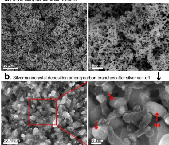
According to our previous experiences in generating nanostructured hybrid materials by using metal acetylides[15-17], we have found a new way of synthesizing mesoporous carbon nanodendrites by using silver acetylide (Ag2C2). Fig. 2.2a shows SEM images of Ag2C2 dendriform monoliths obtained by 10 min synthesis. The size of the monoliths amounts to a few hundred micrometers large although the size of the branches is on average 25 nm wide in this case. After the segregation reaction to gaseous silver and solid carbon, the erupted silver vapor deposited as nanocrystals (indicate by arrows) among the carbon skeletons as shown in Fig. 2.2b. Since the carbon bodies are so thin that the electrons penetrate through the carbon bodies exhibiting the silver crystals behind them. The silver nanocrystals attached on the dendrites were removed by nitric acid and washed with hot water to remove silver nitrate. Silver nitrate is recovered as white crystals by the distillation of nitric acid and reused as the starting material for the Ag2C2
synthesis.
Figure 2.2 (a) SEM images of an Ag2C2 dendroid monolith. (b) after the segregation reaction of the Ag2C2 dendrites, the silver vapor deposits as nanocrystals among the so thin carbon skeletons. Hence the secondary electrons from the silver crystals can penetrate the carbon skeleton and get in to the detector.
2.3.2 MCND structure
The mesoporous carbon product was named mesoporous carbon nano-dendrite (MCND). Fig. 2.3a shows a SEM image of the dendroid structure and the presence of opening spaces among the branches. The main body with an average size of 50nm ramifies at every 100-150 nm. The space among the branches is very effective in rapid ion transportation for charge-discharge processes of the batteries. Fig. 2.3b shows a magnified SEM image of an outer edge area of the dendrite. On the right side, stacking of many pores aligned inside the surface can be also observed, although the size and shapes are not regular. Fig. 2.3c is a TEM image of MCND branches. One can recognize the homogeneity of the branch size and the inhomogeneous distribution of the pore size. The surface thickness can be observed in the cross-sectional TEM images in Fig. 2.3d-f. The outer surface membranes are triple or double layered graphene sheets with bent or gently curved structure. In general, the pores in the outer region are rather large as demonstrated by a big pore with graphene double walls seen in the left side of Fig. 2.3e. The inner regions of Fig. 2.3d-f appear complicated due to the overlaps with many small single or double wall, while triple layer of the outer sheets on the surface show inter-layer spacing of 0.36 (±0.02) nm.
These images exhibit the presence of the surface-skin and stacked pores
Figure 2.3 SEM and TEM images of MCND. (a) SEM image showing dendroid evolution of the carbon body. (b) high resolution SEM image of the edge region of the dendrite. (c) a TEM image of the MCND branches. (d-f) cross-sectional images of double or triple layered graphene structure of outer surface of MCND.
where originally high temperature silver vapor existed in a very short time just before the eruption. Thus every pore is connected through commutable spaces that can be filled with gas or fluid. The TGA result of MCND is represented in Fig. 2.4. Weight loss due to combustion was started to observe ca. 500 °C, and the MCND was completely burned out by ca. 660 °C. This profile showed almost a single component at a combustion temperature around 600 °C consistent with the double or triple graphene wall structure seen in the TEM images. Even after the high temperature boiling and eruption of silver, the monolith structure of the residual carbon networks are maintained in a scale as big as several microns to several hundred microns.
Figure 2.4 TGA result for MCND at a heating rate of 10 °C/min under dry air flowing, and the combustion temperature is close to those of single wall and multi wall carbon nanotubes[18-19].
2.3.3 Spectroscopic characterization
Microscope imaging is not sufficient to prove that the structure of the dendrites is graphene-like. Dato et al. have shown the EELS and Raman studies of single and double layers of graphene sheets[20]. Fig. 2.5 shows an EELS spectrum in the carbon K-edge region that shows a clear peak at 285 eV and a peak at 292 eV, due to the transitions from the 1s to the π* state and to the σ* state, respectively. Suenaga et al. also reported the EELS spectra of various carbon nano objects[21]. The spectrum in Fig. 2.5 is close to that of the double layered graphene sheets and also to the double walled carbon nanotubes. The 285 eV band is clearly resolved as compared with that seen in the single graphene sheet reported by Dato et al.[20]
On the lower side of Fig. 2.6, the Raman spectra of MCND in the G and D band region (a) and 2D region (b) are shown as well as those band of highly oriented pyrolytic graphite (HOPG) sample on the top for reference. The G band of MCND is composed with the stronger peak at 1584(±1) cm-1 and weaker peak at 1612(±1) cm-1. The similar band composition was also seen in the spectrum of functionalized single graphene sheets (FGSs)[22]. The origin of the doublet features of G band has been well characterized, and can be attributed to the nano-sized graphene crystals. The high frequency component increases with
Figure 2.5 EELS spectrum of MCND in the carbon K-edge region taken for the TEM region shown in Fig. 2.3-C.
Figure 2.6 Raman spectra of MCND (bottom lines) and HOPG (top lines) in the G band region (a) and 2D band region (b). For the frequency calibration, the oxygen molecular line (the peak shown by *) at 1554.7 cm-1 was included in the same spectra. The spectra were analyzed as two Lorentzian components for the four spectra. Allow shows the frequency position of a graphene sheet taken from Ref. [23].
decreasing crystal size. According to the literature[23-25], a similar spectral feature of the G band was observed in the spectra of the graphite crystals with size of ∼5 nm. Thus, the high frequency component at 1612 cm-1 is characteristic of nanosized graphene moieties in MCND, similar to those seen in FGSs. In the present work, the frequency numbers are so serious that we calibrated the observed frequencies with the marker signal of the gas phase oxygen[26] at 1554.7 cm-1. With stacking more graphene layers, the peak frequency of G band shifts 5 cm-1 lower from the value of the single-layer (1585 cm-1) to those for the n layers (n = 2-6; 1579 cm-1)[20,22-25]. The value of 1584 cm-1 for the main peak, therefore, can be primarily attributed to the single graphene sheet. Recently, several groups have reported that the shapes and positions of the overtone 2D band at ∼2700 cm-1 are clear finger-point for assigning the number of graphene layers[21-23]. The peak position shifts to the higher frequency region when changing from a single-layer to double-layer. The 2D peak positions of the single graphene sheets for a 514.5 nm excitation is observed at 2679(±1) cm-1, while the 2D band of double layer shifts to higher frequencies by 19 cm-1 [25]. The peak positions of the triple and quadruple layered graphenes are similar to that of the double layer sheets. As shown in the HOPG spectrum, the 2D band of graphite appears at 2724 cm-1. This frequency is larger by 44 cm-1 than that of single graphene. The peeak position of the observed 2D band of MCND (Fig.2.6b) is seen at 2680(±1) cm-1, which is almost the frequency of the single graphene but
far from those of double or multi-layered graphene (2694-2724 cm-1). The 2D band feature is consistent with that observed in the G band analysis. Thus, we assign that the observed band at 2680 cm-1 originates mostly from single graphene walls. Raman observation reflects the structural information in a submillimeter region irradiated with the focused laser beam, while the EELS is limited to the submicron region of the edge part of MCND monoliths. Therefore, the Raman information could be related to the structure of the major part of MCND. The contribution from the walls inside the dendrites can be most dominant in the Raman spectra.
2.3.4 Porosity characterization
Not only the microscope observation but also the spectroscopic data suggest that the MCND is composed of graphitic or graphene walls for mesoporous pores. It is necessary to know the surface area and the pore size distribution. The adsorption-desorption curves are shown in Fig. 2.7 that indicate the presence of micropores and mesopores with a continuous size distribution up to 10-20 nm. This is also consistent with the TEM images shown in Fig. 2.3. It is interesting that the BET surface area of sample (a) with an average body diameter of 50 nm is 1610 m2/g, and that of sample (b) with diameter of 25 nm is 1324 m2/g. Sample (a) was obtained for an Ag2C2 synthesis time of 30 min, while sample (b) was only 10 min. At a partial pressure of 0.99, the weight of the adsorbed nitrogen exceeds 2.4 g for 1 g of MCND particles. This value also indicates the largeness of the total pore volume. Fig. 2.7 compares the adsorption isotherm of a commercial activated carbon (Kuraray. YP-17, BET surface area = 1690 m2/g) that does not show any mesopore characteristics. DFT differential pore volume distribution obtained by the adsorption curves showed two peaks at 0.7 and 1.3 nm in the micropore region and an estimate peak at 2.8 nm in the mesopore region. As clearly seen in the Fig. 2.8, the mosopore size is continuously distributed up to the 10 nm region and the mesopore volume is much larger than the micropore volume. The ratio is variable dependent on the synthetic condition. MCND with a
wider branch radius provided a larger BET surface area and exhibited the increasing dominancy of larger pores.
Figure 2.7 Nitrogen adsorption and desorption isotherms of MCNDs and activated carbon. Two types of adsorption and desorption curves of MCNDs are shown for sample (a) (average body size, 50 nm) and sample (b) (25 nm). The curve (c) represent adsorption and desorption behavior of a commercial activated carbon for supercapacitor use (Kuraray, YP-17).
Figure 2.8 The pore size distributions of MCNDs (red line) and commercial activated carbon (YP-17) calculated by the DFT method.
2.4 Conclusions of this chapter
A novel mesoporous carbon nano-dendrite with ultra-thin graphitic walls is obtained by controlling the explosive segregation reaction of dendroid Ag2C2 into silver vapor and carbon skeletons. The body of the porous dendrite is composed of typically 50 nm rods branching at every 100-150 nm. Raman spectra suggest that the main part of the walls is composed of single graphene sheets while TEM images show the presence of big pores on the outer most surface side made of double or triple layer graphitic walls.
2.4 Reference for Chapter 2
[1] J.C. Meyer, A.K. Geim, M.I. Katsnelson, K.S. Novoselof, T.J. Booth and S. Roth, Nature, 446, 60, (2007).
[2] T. Kyotani, T. Nagai, S. Inoue and A. Tomita, Chemistry of Materials, 9, 609, (1997).
[3] R. Ryoo, S.H. Joo, M. Kruk and M. Jaroniee, Advanced Materials, 13, 677, (2001).
[4] J. Chmiola, G. Yushin, Y. Gogotsi, C. Portet, P. Simon and P.L. Taberna, Science, 313, 1760, (2006).
[5] T.W. Kim, I.S. Park and R. Ryoo,
Angewandte Chemie International Edition, 42, 4375, (2003). [6] C.D. Liang, K.L. Hong, G.A. Guiochon, J.W. Mays and S. Dai, Angewandte Chemie International Edition, 43, 5785, (2004). [7] S. Tanaka, N. Nishiyama, Y. Egashira and K. Ueyama, Chemical Communications, 4, 2125, (2005).
[8] J. Lee, J. Kim and T. Hyeon, Advanced Materials, 18, 2073, (2006). [9] C.H. Kim, D.K. Lee and T.J. Pinnavaja,
Langmuir, 20, 5157, (2004).
[10] H. Yang, Y. Yan, Y. Liu, F. Zhang, R. Zhang, Y. Meng, M. Li, S. Xie, B. Tu, and D. Zhao, The Journal of Physical Chemistry B, 108, 17320, (2004). [11] Y.D. Xia and R. Mokaya, Advanced Materials, 16, 1553, (2004). [12] R.K. Dash, J. Chimola, G. Yushin, G. Laudisio, J. Singer and J. Fischer et al. Carbon, 44, 2489, (2006).
[13] N. Tonanon, A. Siyasukh, Y. Wareenin, T. Charinpanitkul,
W. Tanthapanichakoon, H. Nishihara, S. R. Mukai, and H. Tamon, Carbon, 43, 2808, (2005).
[14] B. Y. Xia, J. N. Wang, X. X. Wang, J. J. Niu, Z. M. Sheng, M. R. Hu, and Q. C. Yu, Advanced Functional Materials, 18, 1790, (2008). [15] K. Kosugi, M. J. Bushiri and N. Nishi,
Applied Physics Letters, 84, 1753, (2004).
[16] K. Judai, J. Nishijo and N. Nishi, Advanced Materials, 18, 2842, (2006). [17] K. Judai, S. Numao, A. Furuya, J. Nishijo and N. Nishi,
Journal of the American Chemical Society, 130, 1142, (2008).
[18] D. Bom, R. Andrews, D. Jacques, J. Anthony, B. Chen, M. S. Meier and J. P. Selegue, Nano Letters, 2, 615, (2002). [19] M. Zhang, M. Yudasaka, A. Koshio and S. Iijima,
Chemical Physics Letters, 364, 420, (2002).
[20] A. Dato, V. Radmilovic, Z. Lee, J. Phillips and M. Frenkach, Nano Letters, 8, 2012, (2008).
[21] K. Suenaga, E. Sandre, C. Colliex, C.J. Pickard, H. Kataura and S. Iijima, Physical Review B, 63, 165408, (2001).
[22] K.N. Kudin, B. Ozbas, H.C. Schniepp, R.K. Prud’homme, I.A. Aksay and R. Car, Nano Letters, 8, 36, (2008).
[23] A. C. Ferrari, J. C. Meyer, V. Scardaci, C. Casiraghi, M. Lazzeri, F. Mauri, S. Piscanec, D. Jiang, K. S. Novoselov, S. Roth, and A. K. Geim,
Physical Review Letters, 97, 187401, (2006).
[24] M. J. McAllister, J. L. Li, D. H. Adamson, H. C. Schniepp, A. A. Abdala, J. Liu, M. H. Alonso, D. L. Milius, R. Car, R. K. Prud'homme,
and I. A. Aksay, Chemistry of Materials, 19, 4396, (2007).
[25] D. Graf, F. Molitor, K. Ensslin, C. Stampfer, A. Jungen, C. Hierold, and L. Wirtz, Nano Letters, 7, 238, (2007).
[26] G. Herzberg, Molecular spectra and molecular structure (reprint ed.), Spectra of diatomic molecules vol. I, Krieger Publishing Co.,
Malabar, Florida (1989) 62.
Chapter 3
Electrochemical study of MCND electrodes
for supercapacitor application
3.1 Introduction
Supercapacitors have received considerable attention because of their possibility for high-rate energy supply[1]. Among the various kinds of supercapacitor electrode materials, porous carbon materials provide the best electrodes owing to their high specific surface-areas and good electric conductivities[1-2]. The electric capacitance is stored in the electric double-layer at the electrode/electrolyte interface of high surface area materials. Therefore the high surface area is so important for high specific capacitance. In general, activated carbons with very high pore volumes and the surface areas higher than 1000 m2/g have been used for commercial supercapacitor electrodes[3]. However, the commercial activated carbon electrodes with high surface areas are accompanied with various types of micropores, and these complex nanostructures hinder the smooth transportation of electrolyte solution in the inner region of electrode.
Recent demands for the development of the supercapacitor electrode is oriented toward the discovery of new carbon materials with high conductivity both for the electron and ion transportation as well as high surface area[4-9]. The dendritic and mesoporous structures of MCND can be well suited for these requirements. This chapter presents electrochemical data of MCND electrodes in comparison with commercial activated carbons for supercapacitor applications.
3.2 Experimental
3.2.1 Fabrication of MCND electrodes
Sandwich-type capacitors were assembled on a platinum current collector with two carbon electrode sheets composed mainly of MCND, and polytetrafluoroethylene (PTFE) porous separator (Fig 3.1). The MCND electrodes were obtained by mixing MCND (80 wt%), acetylene black (DENKA black, Denki Kagaku Kogyo, 10 wt%) as an electroconductive material, and PTFE binder (PTFE 6-J, Dupont Mitsui Fluorochemicals Co., 10 wt%). The mixed sample was rolled to 250 µm thick sheets. Disk shape electrodes (diameter: 10 mm) were cut out from these sheets by a clicking machine. As a reference, we also prepared the commercially activated carbon (YP-17, Kuraray Co.) electrode with the same procedure.
Figure 3.1 Sandwich-type capacitor cell for electrochemical measurement.
3.2.2 Evaluation of MCND electrodes
Cyclic voltammetry (CV) and constant current charge-discharge measurement were carried out in evaluation of the electrochemical performance. Cyclic voltammograms were recorded on Hokuto Denko HSV-100 within the voltage range from -0.1 to 0.8 V relative to an Ag/AgCl reference electrode at scanning rates of 100, 200, and 300 mV/s in an aqueous electrolyte of 2 M H2SO4
with ultrapure water. Constant current charge-discharge measurement in the voltage range from 0 to 0.9 V was used for the estimation of the specific capacitance C (F/g) and the IR drop (V) associated with an increase in internal resistance. Electrochemical performance of MCND and YP-17 electrodes in organic electrolyte (1 M (C2H5)4NBF4 in propylene carbonate) were also measured between the voltage range from 0 to 2.5 V. Fig. 3.2 shows a typical constant current charge-discharge profiles, the energy and power densities of carbon electrodes were calculated from the constant current discharge curves.
Figure 3.2 A typical constant current charge-discharge profiles.
3.3 Result and Discussion
3.3.1 Cyclic voltammetry
Fig. 3.3 presents the cyclic voltammetry (CV) profiles of MCND and YP-17 electrodes taken at different scan rates between 100 and 300 mV/s. The voltammetric curve dependence on the scan rate was usually used to evaluate high current charge-discharge property of electrode materials. The rectangular shape of voltammogram indicates good capacitive characteristics, and generally the shape became slim and leaf-like with increasing scan rate. The good rectangular curve of MCND at 300 mV/s indicates good capacitive characteristics at high rate sweep charge-discharge operation. However, the rectangular shape of YP-17 becomes distorted even at 100 mV/s. These results show that efficient ion diffusivity and good electron conductivity for the MCND electrodes. A hump around 0.5 V is attributed to silver nitrate trapped in the deep inside of the micro pores of MCND on the basis of the reported oxidation/reduction potential[10]. The TGA measurement of the sample indicated the presence of 0.7 % of silver in the MCND. The use of the thicker electrodes (360 µm) does not change the electrochemical performance for supercapacitors while the working current increases. Up to the maximum current limit of our apparatus, we could not see any smoothing effect of the CV measurement.
Figure 3.3 Cyclic voltammograms of a MCND supercapacitor with an electrode thickness of 250 µm. Although the commercial activated carbon never shows a rectangular response with changing potentials at a scan rate faster than 50 mV/s, MCND can afford high-speed charge-discharge performance at a rate faster than 300 mV/s and current densities higher than 30 A/g.
3.3.2 Constant current charge-discharge measurement
Fig. 3.4 shows the charge-discharge profiles of the MCND electrode at constant current densities of 2, 5, and 10 A/g. The plot of the YP-17 measured at 2 A/g is also included for comparison. The specific discharge capacitance (C) for a two-electrode cell was calculated according to C (F/g) = IΔt/ΔV, where I, Δt, and ΔV are the discharge current, the discharge time, and the voltage change in discharge excluding the portion of IR drop, respectively. The specific capacity of YP-17 is no more than 16.0 F/g at the current density of 2 A/g. In contrast, the discharge curve of MCND exhibits a large capacitance (26.5 F/g) and a small IR drop even at 10 A/g. Presence of mesopores and the dendritic structure of MCND provides good ion diffusivity in the inner region of the electrode, can result in large capacitance and lower internal resistance. The time scale is in the region of 1-20 seconds for the charge-discharge between -0.1 V and 0.8 V. One can compare the present results with the recent excellent data reported by Wang et al.[9] The currents are five times higher, while the time scale is shortened to 1/20. Thus, thanks to excellent conductivities of ion in the electrolyte and electrons in electrodes, the MCND electrodes work well as a supercapacitor at current densities higher than 10 A/g.
The ragone plots for MCND electrodes in aqueous and organic solution are
Figure 3.4 Constant current charge-discharge profiles of MCND electrodes with an electrode thickness of 250 µm.
shown in Fig. 3.5, which shows the energy and power relationship of the capacitors. The plots of the YP-17 are also included for comparison. The energy density (E) was calculated according to E = (1/2)CV2, where C and V are the capacitance of the two-electrode capacitor, and the cell voltage in discharge, respectively. And the power density (P) was calculated according to P = E/Δt, where Δt is discharge time. The energy densities of MCND and YP-17 electrodes at low power densities are roughly similar. However, the energy density of YP-17 decreases sharply from 3.4 to 0.26 Wh/kg with increasing power density from 21 to 924 W/kg. In contrast, the MCND electrodes have achieved an energy density as high as about 2.0 Wh/kg at a power density of 3730 W/kg. This experimental evidence indicates that the energy loss is very little at high power use when using the MCND electrode. Moreover, this excellent property of MCND electrodes at high rate charge-discharge operations has been also indicated in organic electrolyte, because the mesopores and dendritic structure of MCND assist smooth diffusion of big organic ions with high rate operations. We believe that the electrochemical characteristics of MCND electrode are the performance for supercapacitor electrodes demanded right at now.
Figure 3.5 Ragone plot of MCND(red line) and YP-17(blue line) supercapacitors, which measured in aqueous(solid line) and organic(dash line) electrolyte.
3.4 Conclusions of this chapter
MCND electrodes for supercapacitors were prepared. A MCND supercapacitor can afford high-speed charge-discharge performance. Cyclic voltammograms of MCND electrodes show that a good rectangular shape at 300 mV/s. Constant current charge-discharge measurements were also used in evaluation of the electrochemical performance of MCND as the supercapacitor electrode for high speed charge-discharge operations. As a result, the ragone plots of MCND electrodes in aqueous and organic solution indicate the excellent property of MCND electrodes for high rate charge-discharge operations.
3.4 Reference for Chapter 3
[1] A.G. Pandolfo and A.F. Hollenkamp, Journal of Power Sources, 157, 11, (2006).
[2] D. Qu and H. Shi, Journal of Power Sources, 74, 99, (1998). [3] H. Shi, Electrochimica Acta, 41, 1633, (1996).
[4] S. Álvarez, M.C. Blanco-López, A.J. Miranda-Ordieres, A.B. Fuertes, and T.A. Centeno, Carbon, 43, 866, (2005).
[5] W. Xing, S.Z. Qiao, R.G. Ding, F. Li, G.Q. Lu, Z.F. Yan, and H.M. Cheng, Carbon, 44, 216, (2006).
[6] E. Raymundo-Piñero, F. Leroux, and F. Béguin, Advanced Materials, 18, 1877, (2006).
[7] H. Yamada, H. Nakamura, F. Nakahara, I. Moriguchi, and T. Kudo, The Journal of Physical Chemistry C, 111, 227, (2007).
[8] S. W. Woo, K. Dokko, H. Nakano and K. Kanamura, Journal of Materials Chemistry, 18, 1674, (2008).
[9] D. W. Wang, F. Li, M. Liu, G. Q. Lu, and H. M. Cheng, Angewandte Chemie International Edition, 47, 373, (2008). [10] D.R. Lide (75th ed.), CRC handbook of chemistry and physics, Boca Raton: CRC Press; 8 (1995).
Chapter 4
Synthesis and characterization of
Sn/MCND composites
as anode materials for Lithium-ion batteries
4.1 Introduction
The lithium-ion battery is of considerable practical interest because of its large specific charge and discharge capacity, which is almost 2 times higher than that of the nickel-metal-hydride battery. Consequently, the lithium-ion battery is beneficial for a main power source for the practical use in mobile communication devices and variety portable electronic devices, such as notebooks, mobile phone etc. In this storage system, the lithium insertion-extraction process between cathode and anode materials is the fundamental electrochemical reaction. As regards a standard anode material, graphite is usually used as the electrode because of it high reversible capacity and high stability[1-3]. But the lithium storage capacity should be much higher for the practical use for electric vehicles etc. Recently, tin (Sn) based materials have been regarded as one of the new generation anode materials of the lithium-ion batteries due to their capacities[4] larger than that of graphite (Sn: Ca.990 mA/g, SnO2: Ca.790 mA/g, and graphite:
Ca.370 mA/g, respectively). However, the lithium insertion-extraction processes into Sn-Li alloys are accompanied by the serve volume change and pulverization of Sn crystals. These volume changes and pulverization lead to the electrode cracking, which causes the loss of electrical contact at the electrode and to very rapid capacity decay. To solve such problems, a significant progress has been achieved by preparing Sn/Carbon composites[5-13]. In this case, the carbon regions function as absorber for the serve volume change of Sn nano-particles.
For the preparation of the Sn/MCND composite as an anode material for the lithium-ion battery, the Snnano-particles were well dispersed and supported in mesopores of MCND. In this chapter, reasonably good charge-discharge reversibility of the Sn/MCND composite electrode is reported. The structural features of MCND such as dendritic morphology and the presence of mesopores can be responsible to the results. The dendritic morphology of MCND acts as buffer material for the severe volume changes of the Sn regions, and the mesopores on the surface of MCND block the pulverization of Sn regions(see Fig. 4.1).
Figure 4.1 Schematic illustration of a Sn/MCND composite. MCND has sizable spaces for the large volume changes of Sn nanoparticles, and the mesoporous walls tenaciously block the pulverization of Sn nanoparticles.


![Figure 2.4 TGA result for MCND at a heating rate of 10 °C/min under dry air flowing, and the combustion temperature is close to those of single wall and multi wall carbon nanotubes[18-19]](https://thumb-ap.123doks.com/thumbv2/123deta/6167271.105050/41.892.218.667.388.795/figure-heating-flowing-combustion-temperature-single-carbon-nanotubes.webp)


