The automobile industry sees its future in the
continuous development of innovative, net-
worked in-vehicle systems. One answer to the
growing complexity this will bring is to perform
systematic standardization based on AUTOSAR.
Strategies for introducing the new standard
are being investigated in three reference pro-
jects at DENSO CREATE. The company is inten-
sively comparing current procedures and methods
with those required by AUTOSAR, with the aim
of solving possible conflicts and ensuring that
the introduction of AUTOSAR at DENSO runs
smoothly.
Process Requirements
DENSO CREATE, a 100% Japanese subsidiary of the DENSO CORPORA- TION with responsibility for the areas of IT and software development, has carried out a process optimizati- on project for introducing AUTOSAR. AUTOSAR provides a way of descri- bing software in great detail to make it easy to reuse. The various stages of an AUTOSAR-compliant development process produce descriptions of the software architec- ture, the overall system, and the system configurations for individual electronic control units (ECUs). However, there are also conventio- nal development projects running. These have other design steps that must be integrated seamlessly and without conflicts. Three aspects are particularly important:
n It must be possible to define the function architecture with the necessary level of abstraction.
n A control engineer using tools such as Simulink® or dSPACE
AutoBox to develop prototypes must have full freedom to design and must not be restricted by AUTOSAR.
n An ECU supplier must retain the ability to optimize the implemen- tation of a software architecture in specific ways.
One Step at a Time
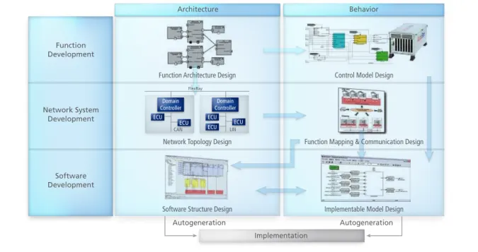
In three reference projects, DENSO CREATE is examining a sequence of major steps and methods which make up an AUTOSAR-compliant development process (figure 1). Architecture modeling and function algorithm modeling are treated separately in these steps:
Function Architecture Design: Define and visualize the necessary function blocks and signals. This step produces a formalized description of essential requirements and can be in the nature of a whiteboard. Early consistency checks can be performed with tool support.
Control Model Design: Add algo- rithms to the defined functions to complete them. This classic form of function modeling is performed with MATLAB®/Simulink® and TargetLink.
Network Topology Design: Define the ECUs and how they are networked.
Function Mapping & Communi- cation Design: When the functions have been mapped to the ECUs, define the local and global commu- nication.
Software Structure Design: Define the software structure to be imple- mented on the ECUs. It may be necessary to transform a structure so that software development meets the given requirements.
Implementable Model Design: Adapt the model to the selected software structure and refine it for the purpose of production code DENSO CREATE
PAGE 20
dSPACE Magazine 1/2010 · © dSPACE GmbH, Paderborn, Germany · [email protected] · www.dspace.com
Talking
AUTOSAR
DENSO CREATE investigates strategies
for introducing the AUTOSAR standard
PAGE21
dSPACE Magazine 1/2010 · © dSPACE GmbH, Paderborn, Germany · [email protected] · www.dspace.com
Domain Controller
ECU ECU
Domain Controller
ECU ECU
ECU Network Topology Design
CAN LIN
Architecture
Function Development
Network System Development
Software Development
Control Model Design
Software Structure Design Implementable Model Design
Autogeneration Autogeneration
Implementation
Behavior
Function Architecture Design
FlexRay
Function Mapping & Communication Design
work methods, costs, and volumes. This made it possible to identify res- ponsibilities, define roles, and opti- mize the procedures for work groups. It was found that control developments, for example, could be carried out in largely the same way as before, without the respon- sible engineers having an in-depth understanding of AUTOSAR. AUTO- SAR-compliant modeling and imple- mentation needs to be performed by a specialist team equipped with suitable development tools.
New Design Environments with Available Solutions
Having gained a thorough know- ledge of the new process, engineers next investigated a tool chain for implementing it. User groups met several times to make basic decisi- ons, after which DENSO CREATE was able to set up a design environ- generation with TargetLink. Example:
Add scaling information and link it to measurement and calibration variables.
Autocode Generation: When the design phase has been completed, generate the software components of the application layer from the implementation models by autoco- ding with TargetLink. Also generate the run-time environment (RTE), and configure and generate the basic software. Example: Generate the communication drivers from the network description.
Implementation: Finally, translate the C source code into object code, link the objects, and load the soft- ware to the ECU.
Each step has its own subset of AUTOSAR description elements specified for it. This ensures that only the really necessary elements are defined in each step.
Roles and Responsibilities for Optimum Efficiency
Efficiency is a major criterion for the new process. The individual steps were studied closely from this point of view to determine the necessary
“ SystemDesk gave ample support to the most
crucial area, linking control algorithm develop-
ment and the AUTOSAR Basic Software on
a model basis, giving us an overview of our
desired ECU design development process.”
Masahiro Goto, DENSO CORPORATION ment based on dSPACE products and supplemented by commercially available solutions.
For the fundamental design of the function architecture, DENSO and DENSO CREATE used SystemDesk from dSPACE. MATLAB/Simulink/ dSPACE RTI and AutoBox were used to verify control functions. System- Desk was then used to derive the software architecture from the function architecture. At this point, EB tresos® from Elektrobit was used to configure the basic software – including RTE generation for con- necting the application software to the basic software. The AUTOSAR- compatible application software was developed with TargetLink. First implementation information was added to the controller models, and then TargetLink converted them into efficient, AUTOSAR-compliant code.
Figure 1: Sequence of major steps and methods in an architecture-based development process. DENSO CREATE
PAGE 22
dSPACE Magazine 1/2010 · © dSPACE GmbH, Paderborn, Germany · [email protected] · www.dspace.com
VFB, RTE, COM, ECUM MCAL
Trial #1 Vehicle Dynamics System Purpose of Trial
Man-months 9.3 man-months 13.4 man-months 18.0 man-months
Perform architecture based development
Establish how to reuse legacy software
Establish how to adapt production program Number of SW-C/Runnables
Number of DataElements/ Communication messages Basic software (BSW) module used
6/11
42/5 (trans.), 5 (recv.)
Mainly COM Stack (partially MCAL) Learning AUTOSAR
specification
Set up engineering environment (Development environment, Design direction)
Resolve inconsistency among tools
Experience debug know-how (Understand BSW structure etc.)
Development SizeResult
Trial #2 Display System (Dashboard)
Trial #3 Air Conditioning System
VFB, RTE, COM, ECUM
26/299
56/3 (trans.), 18 (recv.)
Mainly MCAL (legacy COM is used)
Plan the direction how to implement legacy software into AUTOSAR structure Experience debug know-how VFB, RTE, COM, ECUM MCAL
41/141
59/5 (trans.), 14 (recv.)
COM Stack, ECUM, MCAL etc.
Execute with experiences of trial #1 and #2 (Evaluate tool chain and design direction)
Various Application Practices DENSO CREATE carried out three subprojects in total, each with its own focus (figure 2), with applica- tions from different vehicle domains.
n The first subproject focused on proving that the tools could be integrated seamlessly.
n The second subproject looked at how to reuse existing software. Information was gathered on the methodical development and inte gration of such software, for example, on the issue of whether sensor and actuator functions should be developed as software components.
n The third subproject studied the software in an existing climate conditioning ECU and converted it to AUTOSAR.
Looking Toward the Future DENSO CREATE will continue to develop the process, with a special focus on making the tool chain seam- less. This will cover issues such as automatically transforming specifica- tions between process steps and a mechanism for synchronizing the various development tools in distribu-
ted development work. Last but not least, the performance of verification features such as the new SystemDesk Simulation Module and ways of inte- grating them into the process have to be studied in detail. This will optimize
the process for future and complex tasks and further enhance its efficiency.
Nobuhide Kobayashi, Yasuo Tatematsu, DENSO CREATE Inc.
Masahiro Goto, DENSO CORPORATION
“ We are extremely grateful to dSPACE, not
only for providing AUTOSAR-compliant tools,
but also for working with us on-site in consi-
dering how to apply AUTOSAR appropriately.
We are also grateful for the full training
environment and for the efficient way in
which tools were introduced.”
Nobuhide Kobayashi, DENSO CREATE Inc. Yasuo Tatematsu,
DENSO CREATE Inc.
Yasuo Tatematsu is Project Manager of Software Development Department at DENSO CREATE in Aichi, Japan. Nobuhide Kobayashi,
DENSO CREATE Inc.
Nobuhide Kobayashi is Project Manager of Software Development Department at DENSO CREATE in Aichi, Japan.
Figure 2: Three subprojects with applications from different vehicle domains.
PAGE23
dSPACE Magazine 1/2010 · © dSPACE GmbH, Paderborn, Germany · [email protected] · www.dspace.com