Design and Functions of Porous Organic
Polymers
Huang, Ning
2015
Department of Structural Molecular Science
School of Physical Sciences
SOKENDAI
(The Graduate University for Advanced Studies)
Contents
General Introduction ---1
Part I. Covalent Organic Framework
Chapter 1 ---12
Covalent Organic Frameworks for Carbon Dioxide Capture through Channel-Wall
Functionalization
Chapter 2 ---39
Tailor-Made Pore Surface Engineering in Covalent Organic Frameworks: Systematic
Functionalization for Performance Screening
Part II. Conjugated Micro/Mesoporous Polymers
Chapter 3 ---64
High-Performance Heterogeneous Catalysis with Surface-Exposed Stable Metal
Nanoparticles
Chapter 4 ---87
Controlled Synthesis of Conjugated Microporous Polymer Films: Versatile Platforms
for Highly Sensitive and Label-Free Chemo- and Biosensing
Chapter 5 ---116
Summary and Perspectives
List of Publications ---120
General Introduction
Porous materials play important roles in various areas ranging from science to technology and have attracted considerable attention as a useful platform for advanced functional materials. In the last decades, the field of porous organic materials has attracted considerable attention because of the distinguished performance and widespread applications such as gas storage, gas separation, superhydrophobic interfaces, catalysis, energy conversion, energy storage, and optoelectronics. Synthetic chemists have developed fesible pathways to prepare a wide number of porous materials; however, it was still a graet challenge to construct organic porous networks by chemical synthesis until the emerge of the concept of reticular chemistry, which employs topologically designed organic molecules as building blocks to construct various novel organic porous materials.
1. Covalent Organic Frameworks
Covalent organic frameworks (COFs) are a novel kind of porous crystalline organic materials assembled from organic molecular building blocks.[1-6] The construction principles of such class of materials allow for the design of precisely controlled structures because their chemical and physical properties can be easily tuned through the selection of the building blocks and the linkage motif.[1] Yaghi and co-workers firstly exhibited the successful utility of the topologically designed principle in the synthesis of porous organic frameworks connected via strong covalent bonds in the solvothermal conditions, namely covalent organic frameworks (COFs) (Figure 1).[2a]
Composed of light-weight elements and linked by strong covalent bonds, covalent organic frameworks, demonstrate very low densities, high thermal and chemical stabilities, as well as permanent porosity.[2-4] Based on the topological design of various building blocks, COFs can be tail-made constructed into both two- (2D) and three-dimensions (3D). As for 2D COFs, the covalent bonded porous structure is sterically confined into 2D sheets which stack together to form a platelike eclipsed structure composed of periodically aligned 1D columns.[3-5] In contrast, 3D COFs, which extend this framework three-dimensionally through a building block containing an sp3 carbon or silane atom (Figure 2), characteristically possess high specific surface areas (in
some cases larger than 4000 m2 g-1), numerous open sites, and low densities (as low as 0.17 g cm-3). These features make 3D COFs ideal candidates for gas storage.
Figure 1. Reversible reactions of boronic acids: (a) self-condensation forms a boroxine ring resulting in a staggered COF-1, and (b) co-condensation with a catechol (HHTP) forms a boronate ester resulting in COF-5. Coloring scheme: C, gray; H, white, B, orange, O, red.
The synthesis of COFs has been achieved by kinetically controlled reactions, which can irreversibly form covalent bonds. Generally, it is very difficult to prepare crystalline organic cross-linked polymers using irreversible reactions. In contrast, dynamic reactions leads to the formation of covalent bonds, which can be reversibly formed, broken, and reformed. Therefore, unlike conventional covalent bond formation, this synthetic strategy is thermodynamically controlled and offers reversible pathway with “error checking” and “proof-reading” characteristics, resulting in the formation of the quite stable structures.
The design and synthesis of COFs have two important issues that must be taken into consideration to achieve thermodynamic control in reversible reactions: the structure of the building blocks and the synthetic method, including the reaction solvent and temperature.
Figure 2. Modeled crystalline structures of COF-102 (A), COF-105 (B), and COF-108 (C).
To obtain crystalline and periodically ordered COFs, the structure of the building blocks must satisfy two required factors: a reversible reaction and the well preserved geometry of the building blocks. A series of reversible reactions have been employed to meet the requirement for successful COF synthesis (Figure 3). Most of the reported frameworks rely on the boron chemistry since boronic acids can be either self-condensed or co-condensed with catechols to form a six-membered boroxine and five-membered boronate ester linkages. Similar to the case of either boroxine or boronate esters, borosilicate linkages have been used to produce COFs through the condensation of a tetraboronic acid with tert-butylsilanetriol.
The specific geometries of building blocks enables the topological design of the COFs. As shown in Figure 3, the geometry of building blocks will determine the resulting structures of COFs. Therefore, the combinations such as 3D-Td + 3D-Td, 3D-Td + 2D-C2, or 3D-Td + 2D-C3 can generate the construction of 3D COFs with different crystalline space groups. In contrast, selected combinations of 2D blocks (e.g., 2D-C2 + 2D-C3, 2D-C3 + 2D-C3 or 2D-C2 + 2D-C4) will afford 2D COFs with predesigned topologies and pore structures (Figure 3). The nature and discrete bonding direction of arenes makes aromatic π systems suitable building blocks for COFs. The diversity of aromatic systems allows numerous building block combinations, which endows the COFs with high flexibility in their topological design.
Figure 3. Schematic representation of the dynamic chemical reactions for the preparation of COFs and the combination of building blocks with different geometries to design 2D COFs.
The function of a COF arises from its porosity and molecular skeletons. As predesignable porous materials, COFs have been emerged as a new media for gas adsorption and storage. These frameworks can be further functionalized to contain catalytic sites for use as heterogeneous catalysts. Because of their unique topology and stacking layer structures, 2D COFs produce columnar arrays throughout their building blocks, which are difficult to synthesize using traditional supramolecular or conventional porous material approaches. In this sense, 2D COFs offer a new platform for the molecular design of semiconducting materials with periodic and built-in molecular ordering.
2. Cojugated Micro/Mesoporous Polymers
Among the covalently linked organic porous materials, CMPs are a class of amorphous materials that allow the linking of building blocks in a π-conjugated fashion and possess three-dimensional (3D) porous networks. Such kind of structural chatacters are very unique and are not available in the other porous counterparts, which are either not π-conjugated, or conventional conjugated polymers, which have no porous structures.[7-12] The first example of CMPs was reported by Cooper and coworks,[7a] after that, a large number of chemists and material scientists have contributed to the development of this field and drive the rapid growth of the CMP family. CMPs are unique in that they allow the complementary utilization of π-conjugated skeletons and nanopores for functional exploration; they have shown great potential for challenging energy and environmental issues, as exemplified by their excellent performance in gas adsorption, heterogeneous catalysis, light emitting, light harvesting and electrical energy storage.
Figure 4. Schematic representation of the structures of building blocks with different geometries, sizes and reactive groups for the synthesis of CMPs.
The network architecture of CMPs have some demands that building blocks have at least two reactive sites. To construct the porous structure, connecting building blocks with different
functions and geometries to build a 3D polymer skeleton is necessary, whereas self-condensation reactions can contribute to homo-coupling of building blocks. Building blocks can be classified by their geometries into C2, C3, C4 and C6 categories (Figure 4). Self-condensation can result in the formation of 3D networks. At the same time, cross-coupling reactions typically use such combinations as C2 + C3,[7a,11e] C2 + C4,[11f,12a] C2 + C6,[12b] C3 + C4, C3 + C6 or C4 + C6.[12c] In both cases, nanopores are generated in confined 3D networks by covalent bonds, with permanent porosity in the resulting CMPs.
In order to build conjugated porous structures, the synthetic method must be able to link different kinds of building blocks with a covalent bond. Chemical reactions employed for the synthesis of linear conjugated polymers can also be utilizedf or CMP synthesis. Numerous coupling reactions, such as Suzuki cross-coupling, Yamamoto reaction, Sonogashira-Hagihara reaction, oxidative coupling reaction, Schiff-base reaction, Friedel-Crafts reaction, phenazine ring fusion reaction and cyclotrimerization have been well developed for the synthesis of CMPs. In iew of building blocks with different geometries, reactive sites, and π systems, the structural diversity significantly endows the flexibility of the design of desired skeletons and pores.
CMPs are also specific since they are nanoporous and π-conjugated, however, their structures can be easily designed and synthesized at the molecular level and topologically controlled. Resulting from high surface areas and porous characteristics, CMPs have come out as a new class of porous materials for gas storage and seperation. The inherent porosity supply open space and are accessible for various guest molecules and metal ions, allowing for the construction of supramolecular structures and organic-inorganic hybrids. Significantly, CMPs enable the complementary utilization of π-conjugated skeletons and nanopores for functional application.
They have demonstrated great potential for challenging energy and environmental problems, as exemplified by their outstanding performance in such applications as gas adsorption, heterogeneous catalysis, light emitting, light harvesting and electric energy storage.
In summary, CMPs are a fascinating kind of materials with great potential for applications. The past efforts on the design, synthesis and functional exploration have demonstrated that CMPs are a versatile platform for structural and functional designs, which will continuously drive the further advancement of this emerging field.
3. Scope of This Thesis
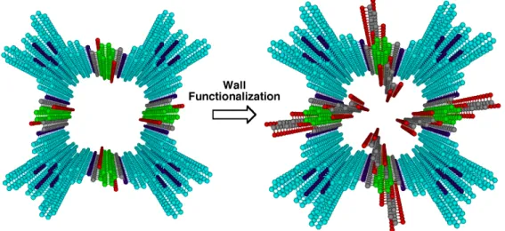
In Chapter 1 and Chapter 2, I report a facile strategy for the pore surface functionalization of covalent organic frameworks (COFs) via a post-synthetic ring-opening and click reaction protocol, respectively (Figure 5). This approach allows the integration of functionalities such as carboxylic acid, amine, alcohol groups to the pore walls and combines a number of striking features including high-throughput synthesis, high crystallinity, large porosity, and robust chemical stability. The pore surface functionalization exerts a prominent effect on the uptake of carbon dioxide by increasing the capacity to 3-4 folds, which ties the highest capacity among the porous materials. These considerable effects demonstrate the significance and effectiveness of rational post-synthetic functionalization of pore surface in the exploration of COF.
Figure 5. Eclipsed stack of phthalocyanine 2D sheets and microporous channels in NiPc-COF (a 2
2 grid). Colors used for identification are as follows: phthalocyanine unit (sky blue), Ni (green), N (violet), C (grey), O (red), B (orange) and H (white).
In Chapter 2, highly cross linked mesoporous conjugated polymer H2P-CMP stabilized Pd nanoparticles (PdNPs⊃H2P-CMP) were prepared by straightforward post synthetic method. The catalytic activity of PdNPs⊃H2P-CMP was high enough for Suzuki cross coupling reactions of aryl chlorides under thermal and microwave heating conditions in aqueous solution. PdNPs⊃H2P-CMP exhibited high catalytic activity and recycled for eight times with loss of activity (Figure 6).
Figure 6. Uncovered and stable palladium nanoparticles are synthesized by using a mesoporous π-network are disclosed to serve as high performance heterogeneous catalyst in water.
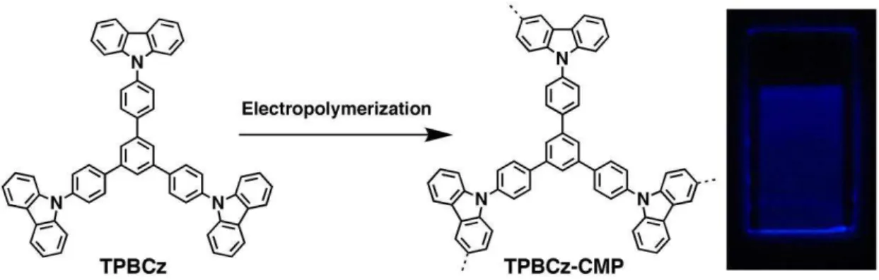
In Chapter 3, I firstly developed a methodology using electropolymerization for the synthesis of thin CMP films (Figure 7). The thickness of these films is synthetically controllable, ranging from nanometers to micrometers, and they are obtained on substrates or as freestanding films. The CεP films combine a number of striking physical properties, including high porosity, extended π conjugation, facilitated exciton delocalization, and high-rate electron transfer. I explored the CMP films as versatile platforms for highly sensitive and label-free chemo- and biosensing of electron-rich and electron-poor arenes, metal ions, dopamine, and hypochloroic acid, featuring rapid response, excellent selectivity, and robust reusability.
Figure 7. a) Schematic representation of the electrochemical synthesis of TPBCz-CMP films. b) Elementary pore of the film. Photos of c) a film on an ITO substrate (0.5×1.5 cm2), d) the film under UV light, and e) a 100 nm thick freestanding film (0.5×1 cm2) in acetonitrile. Scale bars: 0.5 cm.
References
1. X. Feng, X. Ding, D. Jiang, Chem. Soc. Rev. 2012, 41, 6010-6022.
2. a) A. P. Côté, A. I. Benin, N. W. Ockwig, M. O'Keeffe, A. J. Matzger, O. M. Yaghi, Science 2005, 310, 1166-1170; b) H. M. El-Kaderi, J. R. Hunt, J. L. Mendoza-Cortés, A. P. Côté, R. E. Taylor, ε. O’Keeffe, O. ε. Yaghi, Science 2007, 316, 268-272; c) A. P. Côté, H. M. El-Kaderi, H. Furukawa, J. R. Hunt, O. M. Yaghi, J. Am. Chem. Soc. 2007, 129, 12914-12915; d) J. R. Hunt, C. J. Doonan, J. D. LeVangie, A. P. Cote, O. M. Yaghi, J. Am. Chem. Soc. 2008, 130, 11872-11873; e) C. J. Doonan, D. J. Tranchemontagne, T. G. Glover, J. R. Hunt, O. M. Yaghi, Nature Chem. 2010, 2, 235-238. f) S. Wan, F. Gndara, A. Asano, H. Furukawa, A. Saeki, S. K. Dey, L. Liao, M. W. Ambrogio, Y. Y. Botros, X. Duan, S. Seki, J. F. Stoddart, O. M. Yaghi, Chem. Mater. 2011, 23, 4094-4097; g) F. J. Uribe-Romo, C. J. Doonan, H. Furukawa, K. Oisaki and O. M. Yaghi, J. Am. Chem. Soc. 2011, 133, 11478-11481.
3. a) R. W. Tilford, W. R. Gemmill, H. C. zur Loye, J. J. Lavigne, Chem. Mater. 2006, 18, 5296-5301; b) R. W. Tilford, S. J. Mugavero, P. J. Pellechia, J. J. Lavigne, Adv. Mater. 2008, 20, 2741-2746; c) L. M. Lanni, R. W. Tilford, M. Bharathy, J. J. Lavigne, J. Am. Chem. Soc. 2011, 133, 13975-13983; d) M. Dogru, A. Sonnauer, A. Gavryushin, P. Knochel, T. Bein, Chem. Commun. 2011, 47, 1707-1709.
4. S. Y. Ding, J. Gao, Q. Wang, Y. Zhang, W. G. Song, C. Y. Su and W. Wang, J. Am. Chem. Soc. 2011, 133, 19816-19822.
5. a) S. Wan, J. Guo, J. Kim, H. Ihee, D. Jiang, Angew. Chem. 2008, 120, 8958-8962; Angew. Chem. Int. Ed. 2008, 47, 8826-8830; b) S. Wan, J. Guo, J. Kim, H. Ihee, D. Jiang, Angew. Chem. 2009, 121, 5547-5550; Angew. Chem. Int. Ed. 2009, 48, 5439- 5442; c) A. Nagai, Z. Guo, X. Feng, S. Jin, X. Chen, X. Ding, D. Jiang, Nat. Commun. 2011, 2, 536; d) X. Ding, J. Guo, X. Feng, Y. Honsho, J. D. Guo, S. Seki, P. Maitarad, A. Saeki, S. Nagase, D. Jiang, Angew. Chem. 2011, 123, 1325-1329; Angew. Chem. Int. Ed. 2011, 50, 1289-1293; e) X. Ding, L. Chen, Y. Honso, X. Feng, O. Saengsawang, J. D. Guo, A. Saeki, S. Seki, S. Irle, S. Nagase, V. Parasuk, D. Jiang, J. Am. Chem. Soc. 2011, 133, 14510-14513; f) X. Feng, L. Chen, Y. P. Dong, D. Jiang, Chem. Commun. 2011, 47, 1979-1981; g) X. Feng, L. Chen, Y. P. Dong, D. Jiang, Chem. Commun. 2011, 47, 1979-1981; h) X. Feng, L. Liu, Y. Honsho, A. Saeki, S. Seki, S. Irle, Y. P.
Dong, A. Nagai, D. Jiang, Angew. Chem. 2012, 124, 2672-2676; Angew. Chem. Int. Ed. 2012, 51, 2618-2622; i) X. Feng, L. Chen, Y. Honsho, O. Saengsawang, L. Liu, L.Wang, A. Saeki, S. Irle, S. Seki, Y. P. Dong, D. Jiang, Adv. Mater. 2012, 24, 3026-3031; j) X. Ding, X. Feng, A. Saeki, S. Seki, A. Nagai, D. Jiang, Chem. Commun. 2012, 48, 8952-8954; k) X. Feng, Y. P. Dong, D. Jiang, CrystEngComm. 2013, 15, 1508-1511; l) X. Chen, M. Addicoat, S. Irle, A. Nagai, D. Jiang, J. Am. Chem. Soc. 2013, 135, 546-549; m) S. Jin, X. Ding, X. Feng, M. Supur, K. Furukawa, S. Takahashi, M. Addicoat, M. E. El-Khouly, T. Nakamura, S. Irle, S. Fukuzumi, A. Nagai, D. Jiang, Angew. Chem. 2013, 125, 2071-2075; Angew. Chem., Int. Ed. 2013, 52, 2017-2021; n) A. Nagai, X. Chen, X. Feng, X. Ding, Z. Guo, D. Jiang, Angew. Chem. 2013, 125, 3858-3862; Angew. Chem., Int. Ed. 2013, 52, 3770-3774; o) S. Jin, K. Furukawa, M. Addicoat, L. Chen, T. Seiya, S. Irle, T. Nakamura, D. Jiang, Chem. Sci. 2013, 4, 4505-4511. 6. a) E. L. Spitler, W. R. Dichtel, Nature Chem. 2010, 2, 672-677; b) J. W. Colson, A. R. Woll, A.
Mukherjee, M. P. Levendorf, E. L. Spitler, V. B. Shields, M. G. Spencer, J. Park, W. R. Dichtel, Science 2011, 228, 228-231; c) E. L. Spitler, B. T. Koo, J. L. Novotney, J. W. Colson, F. J. Uribe-Romo, G. D. Gutierrez, P. Clancy, W. R. Dichtel, J. Am. Chem. Soc. 2011, 133, 19416-19421; d) E. L. Spitler, J. W. Colson, F. J. Uribe-Romo, A. R. Woll, M. R. Giovino, A. Saldivar, W. R. Dichtel, Angew. Chem. 2012, 124, 2677-2681; Angew. Chem., Int. Ed. 2012, 51, 2623-2727; e) D. N. Bunck, W. R. Dichtel, Angew. Chem. 2012, 124, 1921-1925; Angew. Chem., Int. Ed. 2012, 51, 1885-1889; f) B. T. Koo, W. R. Dichtel, P. Clancy, J. Mater. Chem. 2012, 22, 17460-17469. g) D. N. Bunck, W. R. Dichtel, Chem. Commun. 2013, 49, 2457-2459; h) C. R. DeBlase, K. E. Silberstein, T.-T. Truong, H. D. Abruña, and W. R. Dichtel, J. Am. Chem. Soc. 2013, 135, 16821–16824; i) H. Xu, X. Chen, J. Gao, J. B. Lin, M. Addicoat, S. Irle, D. L. Jiang, Chem. Commun. 2014, 50, 1292-1294.
7. a) S. H. Chen, R. F. Horvath, J. Joglar, M. J. Fisher and S. J. Danishefsky, J. Org. Chem., 1991, 56, 5834-5845; b) A. Suzuki, Chem. Commun. 2005, 4759-4763; c) Y. F. Wang, W. Deng, L. Liu and Q. X. Guo, Chin. J. Org. Chem. 2005, 25, 8-24; d) J. X. Jiang, F. B. Su, A. Trewin, C. D. Wood, N. L. Campbell, H. J. Niu, C. Dickinson, A. Y. Ganin, M. J. Rosseinsky, Y. Z. Khimyak and A. I. Cooper, Angew. Chem., Int. Ed. 2007, 46, 8574-8578; e) J. Langecker and M. Rehahn,
Macromol. Chem. Phys. 2008, 209, 258-271; f) A. Suzuki, Angew. Chem., Int. Ed. 2011, 50, 6722-6737.
8. a) E. H. Cordes and W. P. Jencks, J. Am. Chem. Soc. 1962, 84, 832-837; b) C. Liu, H. Zhang, W. Shi and A. W. Lei, Chem. Rev. 2011, 111, 1780-1824; c) W. Shi, C. Liu and A. Lei, Chem. Soc. Rev. 2011, 40, 2761-2776; d) R. Chinchilla and C. Nájera, Chem. Soc. Rev. 2011, 40, 5084-5121.
9. a) V. Gevorgyan and Y. Yamamoto, J. Organomet. Chem. 1999, 576, 232-247; b) S. Kotha, E. Brahmachary and K. Lahiri, Eur. J. Org. Chem. 2005, 4741-4767; c) B. Karami and S. Khodabakhshi, J. Serb. Chem. Soc. 2011, 76, 1191-1198.
10. a) M. Yamada, Y. Tanaka, Y. Yoshimoto, S. Kuroda and I. Shimao, Bull. Chem. Soc. Jpn. 1992, 65, 1006-1011; b) M. Hayashi, S. Z. Nakayama and H. Kawabata, Chem. Commun. 2000, 1329-1330; c) P. Kuhn, M. Antonietti and A. Thomas, Angew. Chem., Int. Ed. 2008, 47, 3450-3453; d) S. W. Yuan, B. Dorney, D. White, S. Kirklin, P. Zapol, L. P. Yu and D. J. Liu, Chem. Commun. 2010, 46, 4547-4549; e) J. A. McCubbin and O. V. Krokhin, Tetrahedron Lett. 2010, 51, 2447-2449.
11. a) J. X. Jiang, F. B. Su, A. Trewin, C. D. Wood, H. J. Niu, J. T. A. Jones, Y. Z. Khimyak and A. I. Cooper, J. Am. Chem. Soc. 2008, 130, 7710-7720; b) J. X. Jiang, F. Su, H. Niu, C. D. Wood, N. L. Campbell, Y. Z. Khimyak and A. I. Cooper, Chem. Commun. 2008, 486-488; c) J. Schmidt, M. Werner and A. Thomas, Macromolecules 2009, 42, 4426-4429; d) J. X. Jiang, A. Trewin, D. J. Adams and A. I. Cooper, Chem. Sci. 2011, 2, 1777-1781; e) Y. H. Xu, L. Chen, Z. Q. Guo, A. Nagai and D. Jiang, J. Am. Chem. Soc. 2011, 133, 17622-17625; f) G. Cheng, T. Hasell, A. Trewin, D. J. Adams and A. I. Cooper, Angew. Chem., Int. Ed. 2012, 51, 12727-12731.
12. a) L. Chen, Y. Honsho, S. Seki and D. Jiang, J. Am. Chem. Soc. 2010, 132, 6742-6748; b) Q. Chen, M. Luo, T. Wang, J. X. Wang, D. Zhou, Y. Han, C. S. Zhang, C. G. Yan and B. H. Han, Macromolecules 2011, 44, 5573-5577; c)Y. Kou, Y. Xu, Z. Guo and D. Jiang, Angew. Chem., Int. Ed. 2011, 50, 8753-8757.
Part I
Covalent Organic Frameworks
Chapter 1
Covalent Organic Frameworks for Carbon Dioxide Capture through
Channel-Wall Functionalization
Angew. Chem., Int. Ed., 2015, 54, 2986-2990.
Ning Huang, Xiong Chen, Rajamani Krisna and Donglin Jiang
Abstract: Ordered open channels found in two-dimensional covalent organic frameworks (2D COFs) could enable them to adsorb carbon dioxide. However, the frameworks’ dense layer
architecture results in low porosity that has thus far restricted their potential for carbon dioxide adsorption. Here I report a strategy for converting a conventional 2D COF into an outstanding platform for carbon dioxide capture through channel-wall functionalization. The dense layer structure enables the dense integration of functional groups on the channel walls, creating a new version of COFs with high capacity, reusability, selectivity, and separation productivity for flue gas. These results suggest that channel-wall functional engineering could be a facile and powerful strategy to develop 2D COFs for high-performance gas storage and separation.
Keywords: carbon dioxide; covalent organic frameworks; flue gas separation; gas adsorption; synthesis
Introduction
Covalent organic frameworks (COFs), a class of crystalline porous polymers that allow the atomically precise integration of building blocks into periodicities, have emerged as a new platform for designing advanced organic materials with periodic structures.[1-5] Two-dimensional (2D) COFs have limited surface areas and small pore volumes as a result of their dense π-stacking layer structure, which greatly restricts their potential as a porous medium for the adsorption of gases such as carbon dioxide, methane, and hydrogen. With the exception of two examples utilizing azine[2b] and boronate[3d] linkages that interact with specific gas molecules to exhibit good capacity, the majority of 2D COFs have very low performance in gas adsorption. To improve this situation, I present a strategy that explores the channel walls for functional engineering and demonstrate its significance and effectiveness in the design of 2D COFs for high-performance gas adsorption and separation.
Results and Discussions
Figure 1. a) Synthesis of [HO2C]X%-H2P-COFs with channel–walls functionalized with carboxylic acid groups via the ring-opening reaction of [OH]X%-H2P-COFs with succinic anhydride. Top and
side views of (b) [HO]100%-H2P-COF and (c) [HO2C]100%-H2P-COF. XRD patterns of (f) [OH]X%-H2P-COFs and (g) [HO2C]X%-H2P-COFs.
The advantage of the dense layer structure of 2D COFs is that this architecture enables the dense incorporation of functional groups onto the channel walls. This structural benefit compensates for the low porosity of 2D COFs. I observed that functional engineering of the channel walls converts a conventional 2D COFs into an outstanding carbon-dioxide-capture material. I demonstrated this strategy by using a conventional imine-linked 2D COF (Figures 1a, b, [HO]100%-H2P-COF) as a scaffold with porphyrin at the vertices and phenol units on the pore walls; this 2D COF exhibits a low capacity for carbon dioxide adsorption. The phenol groups undergo a quantitative ring-opening reaction with succinic anhydride that decorate the channel walls with open carboxylic acid groups (Figures 1a, c, [HO2C]100%-H2P-COF). The content of
Figure 2. IR spectra of [OH]X%-H2P-COFs and [COOH]X%-H2P-COFs.
carboxylic acid units on the channel walls was tuned by adjusting the content of phenol groups via a three-component condensation system with a mixture of 2,5-dihydroxyterephthalaldehyde (DHTA) and 1,4-phthalaldehyde (PA) as the wall components (Figure 1a, [HO]X%-H2P-COFs, X
= [DHTA]/([DHTA] + [PA])). Various analytic methods revealed that the DHTA-to-PA molar ratios integrated into [HO]X%-H2P-COFs were identical to those employed for the reactions (Figures 2, 3). Using this method, I synthesized a series of [HO2C]X%-H2P-COFs with controlled carboxylic acid density that varied from 25% to 50%, 75%, and 100% (Figure 1c,). The [HO2C]X%-H2P-COFs were characterized using infrared spectroscopy (Figure 2), elemental and thermogravimetric analysis (Table 1, Figure 3), energy dispersive X-ray spectrometry (Table 2,
Figure 3. a) TGA curves of [HO]X%-H2P-COFs (red: [HO]100%-H2P-COF, green: [HO]75%-H2P-COF, blue: [HO]50%-H2P-COF, black: [HO]25%-H2P-COF); b) TGA curves of [CO2H]X%-H2P-COF.
Figure 4) and X-ray diffraction (XRD) measurements (Figure 1e). These methods reveal that the content of carboxylic acid units integrated into the channel walls is close to the X% value of [HO2C]X%-H2P-COFs. Notably, compared to metal-catalyzed azide-ethynyl[2c, 2d] or other click reactions,[4c] this ring-opening reaction is free of metal catalysts, proceeds smoothly and cleanly, and excludes the formation of metal nanoparticles that would contaminate the channels.
The [HO]100%-H2P-COF samples exhibited strong XRD peaks at 3.49°, 7.21°, and 23.1°, which are assignable to 100, 200, and 001 facets, respectively (Figure 1d, red curve).[2d] Other [HO]X%-H2P-COFs exhibited identical diffraction patterns (Figure 1d). The [HO2C]X%-H2P-COFs exhibit XRD patterns (Figure 1e) similar to those of [HO]X%-H2P-COFs, which indicates that the crystal structure of [HO2C]X%-H2P-COFs is similar to that of [HO]100%-H2P-COF.[2d] The presence
of (001) facet at 23.1°, which correspondis to an interlayer interval of 3.8 Å, indicates that [HO]X%-H2P-COFs and [HO2C]X%-H2P-COFs have dense π-stacking layer structures (Figures 1b, c).
Table 1. Elemental analysis results of [HO]X%-H2P-COFs and [HO2C]X%-H2P-COFs.
COFs C% H% N%
[HO]25%-H2P-COF
Calcd. 76.95 4.25 11.97
Found 74.92 4.88 10.87
[HO]50%-H2P-COF
Calcd. 78.29 4.33 12.17
Found 76.68 4.68 11.54
[HO]75%-H2P-COF
Calcd. 79.67 4.40 12.39
Found 78.24 4.87 10.92
[HO]100%-H2P-COF
Calcd. 81.11 4.48 12.61
Found 78.62 5.03 11.28
[HO2C]25%-H2P-COF
Calcd. 74.05 4.37 10.79
Found 70.42 4.87 8.67
[HO2C]50%-H2P-COF
Calcd. 71.76 4.34 9.85
Found 69.34 4.71 8.72
[HO2C]75%-H2P-COF
Calcd. 69.84 4.31 9.05
Found 68.46 4.92 7.82
[HO2C]100%-H2P-COF
Calcd. 68.21 4.29 8.37
Found 64.43 5.17 7.02
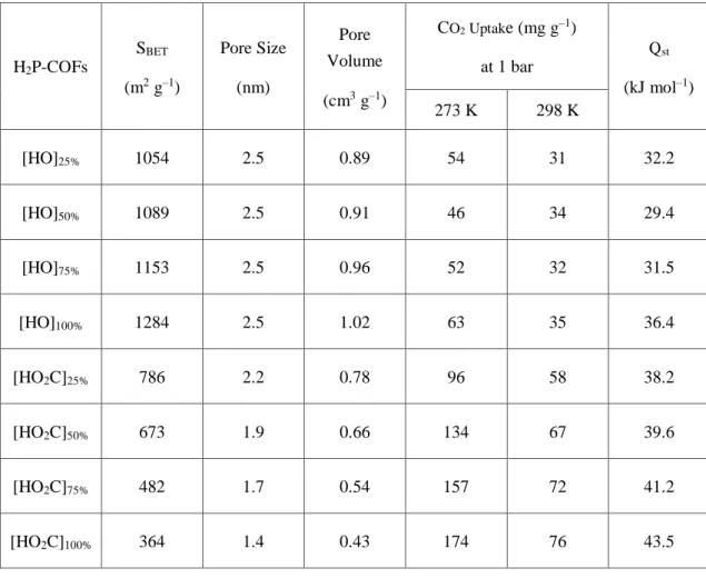
The crystal structures of [HO]X%-H2P-COFs and [HO2C]X%-H2P-COFs suggest the presence of open nanochannels (Figures 1b, c). The [HO]X%-H2P-COFs exhibit typical type-IV nitrogen sorption isotherm profiles indicative of mesoporous character (Figure 5). Notably, the Brunauer-Emmett-Teller (BET) surface area (1054-1284 m2 g–1), pore volume (0.89-1.02 cm3 g–1), and pore size (2.5 nm) remained nearly unchanged (Table 3). Pore size distribution profiles revealed that these COFs possess a single type of mesopores (Figures 5b-e). Therefore, the
three-component condensation reaction is reasonably concluded to allow for the integration of phenol groups in a controlled manner while retaining crystallinity and porosity.
Functionalization of the channel walls with carboxylic acid groups triggers microporosity in [HO2C]X%-H2P-COFs, as evidenced by their typical type-I sorption curves (Figure 5f). The BET
Table 2. Energy dispersive X-ray spectrometry (EDX) analysis of [HO]X%-H2P-COFs and [HO2C]X%-H2P-COFs
COFs C% O% N%
[HO]25%-H2P-COF
Calcd. 76.95 6.83 11.97
Found 77.36 5.92 12.50
[HO]50%-H2P-COF
Calcd. 78.29 5.21 12.17
Found 77.2 5.01 13.41
[HO]75%-H2P-COF
Calcd. 79.67 3.54 12.39
Found 78.8 3.83 12.91
[HO]100%-H2P-COF
Calcd. 81.11 1.8 12.61
Found 82.93 1.81 10.92
[HO2C]25%-H2P-COF
Calcd. 74.05 10.79 10.79
Found 74.50 10.06 11.06
[HO2C]50%-H2P-COF
Calcd. 71.76 14.05 9.85
Found 70.33 14.95 10.38
[HO2C]75%-H2P-COF
Calcd. 69.84 16.8 9.05
Found 68.61 16.98 10.09
[HO2C]100%-H2P-COF
Calcd. 68.21 19.13 8.37
Found 67.08 19.70 8.92
surface area (SBET) decreased from 786 to 673, 482, and 364 m2 g–1, whereas the pore size decreased from 2.2 to 1.9, 1.7, and 1.4 nm (Table 3), as the content of carboxylic groups was increased from 25% to 50%, 75%, and 100%, respectively. The pore volume also decreased from 0.78 to 0.66, 0.54, and 0.43 cm3 g–1, as the content of carboxylic groups was increased. This reduction in porosity is indicative of space filling by the functional units appended to the channel
Figure 4. EDX analysis of [HO]X%-H2P-COFs and [HO2C]X%-H2P-COFs.
Figure 5. a) Nitrogen sorption isotherm curves of [HO]X%-H2P-COFs. b-e) Pore size and pore size distribution profiles of [HO]X%-H2P-COFs. f) Nitrogen sorption isotherm curves of [HO2C]X%-H2P-COFs. g-j) Pore size and pore size distribution profiles of [HO2C]X%-H2P-COFs.
walls. Notably, the pore size distribution profiles revealed that porosity was solely derived from the micropores (Figures 5g-j). This observation suggests that the channel walls were randomly functionalized with carboxylic acid groups in the case of [HO2C]X%-H2P-COFs (X = 25, 50, and 75). Stability test revealed that [HO2C]X%-H2P-COF was stable upon immersion in THF, water, and aqueous HCl (1 M), NaHCO3 (1 M), and KOH (1 M) solutions for 24 h (Figure 6).
Carboxylic acid groups have been reported to trigger a dipolar interaction with carbon dioxide.[6a-6f] In [HO2C]X%-H2P-COFs, the carboxylic acid units are located at the termini and exhibit an acidity similar to that of the free carboxylic acid, as evidenced by their pKa values of 5.86. I first investigated the CO2 adsorption by [HO]X%-H2P-COFs at pressures up to 1 bar and at
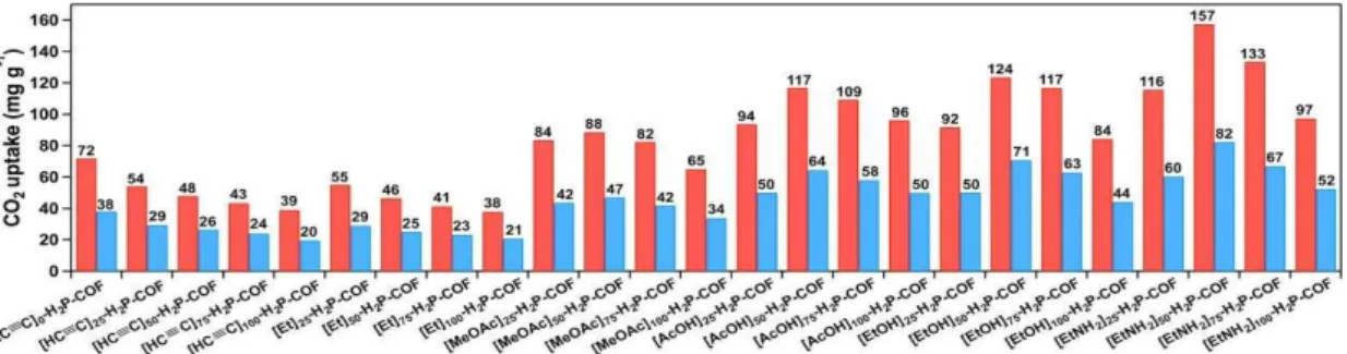
temperatures of 273 K (Figure 7a) and 298 K (Figure 7b). The [HO]X%-H2P-COFs exhibited low capacities between 46 and 63 mg g–1 at 273 K and between 31 and 35 mg g–1 at 298 K (Table 3). By contrast, the [HO2C]X%-H2P-COFs exhibited dramatically increased CO2 adsorption capacities. For example, [HO2C]100%-H2P-COF exhibited a capacity of 180 and 76 mg g–1 at 273 K (Figure 7c) and 298 K (Figure 7d), respectively. These capacities are 2.8- and 2.2-fold greater than those of [HO]100%-H2P-COF (Table 3). Interestingly, the adsorption capacity of [HO2C]X%-H2P-COFs increased in proportion to their carboxylic acid content (Figures 7c, d; Table 3). These positive effects clearly confirmed the effectiveness of channel-wall functionalization in enhancing CO2 adsorption.
Table 3. Porosity, CO2 uptake, and Qst value of [HO]X%-H2P-COFs and [HO2C]X%-H2P-COFs.
H2P-COFs
SBET
(m2 g–1)
Pore Size (nm)
Pore Volume (cm3 g–1)
CO2 Uptake (mg g–1) at 1 bar
Qst
(kJ mol–1)
273 K 298 K
[HO]25% 1054 2.5 0.89 54 31 32.2
[HO]50% 1089 2.5 0.91 46 34 29.4
[HO]75% 1153 2.5 0.96 52 32 31.5
[HO]100% 1284 2.5 1.02 63 35 36.4
[HO2C]25% 786 2.2 0.78 96 58 38.2
[HO2C]50% 673 1.9 0.66 134 67 39.6
[HO2C]75% 482 1.7 0.54 157 72 41.2
[HO2C]100% 364 1.4 0.43 174 76 43.5
Various 2D and 3D COFs with different structures have been previously synthesized and investigated in attempts to develop a practical scaffold for carbon dioxide adsorption. Typical examples include boronate-linked 2D COF-5 (5.9 wt%, SBET = 1670 m2 g–1),[3c] TDCOF-5 (9.2
Figure 6. Stability test of [HO2C]X%-H2P-COFs. The XRD patterns of a) [HO2C]25%-H2P-COF, b) [HO2C]50%-H2P-COF, c) [HO2C]75%-H2P-COF, and d) [HO2C]100%-H2P-COF upon immersion in different solvents at room temperature for 24 h. (e) IR spectra of [HO2C]100%-H2P-COF and the [HO2C]100%-H2P-COF samples upon treatment with different solvents at room temperature for 24 h. These IR spectra revealed that the carboxylic acid groups were retained under these conditions.
wt%, SBET = 2497 m2 g–1),[5a] and 3D COF-103 (7.6 wt%, SBET = 3530 m2 g–1),[3c] imine-linked ILCOF-1 (6.0 wt%, SBET = 2723 m2 g–1)[5b] and TpPa-1 (15.6 wt%, SBET = 535 m2 g–1),[3d] and azine-linked ACOF-1 (17.7 wt%, SBET = 1176 m2 g–1).[2b] The capacity of [HO]100%-H2P-COF (6.5 wt%) is close to those of conventional and non-functionalized COF-5, IL-COF-1, and COF-103. By contrast, the wall-channel functionalized [HO2C]100%-H2P-COF takes up 4.1 mmol g-1 of CO2
(18.0 wt%, 180 mg g–1, SBET = 364 m2 g–1), which is the highest performance among 2D and 3D COFs reported thus far. To the best of my knowledge, the capacity observed for [HO2C]100%-H2P-COF is also comparable to those of other top-class members, including PPN-6-SO3Li (187 mg g–1),6g Amine-PCN-58 (128 mg g-1),[6p] UCBZ-1 (99 mg g-1),[6q] N-TC-EMC (176 mg g–1),[6h] and PPN-6-CH2DETA (190 mg g–1).[6i]
Figure 7. CO2 sorption curves of [HO]X%-H2P-COFs measured at (a) 273 K and (b) 298 K (black: [HO]25%-H2P-COF, blue: [HO]50%-H2P-COF, green: [HO]75%-H2P-COF, red: [HO]100%-H2P-COF). CO2 sorption curves of [HO2C]X%-H2P-COFs measured at (c) 273 K and (d) 298 K (black: [HO2C]25%-H2P-COF, blue: [HO2C]50%-H2P-COF, green: [HO2C]75%-H2P-COF, red: [HO2C]100%-H2P-COF). Open and filled circles represent desorption and adsorption, respectively.
Upon functionalization with carboxylic acid groups that have affinity for carbon dioxide, [HO2C]100%-H2P-COF may exhibit enhanced adsorption selectivity. Based on the CO2 and N2
sorption isotherm curves measured at 298 K (Figures 7, 8), I investigated the selective adsorption of CO2 over N2, which is critical for carbon capture from air or flue gas streams. The ideal absorbed solution theory (IAST) of Myers and Prausnitz[7a] is a well-established model for describing the adsorption of gas mixtures in porous materials. Using pure-component isotherm fits, I determined the adsorption selectivity defined by Sads = (q1/q2)/(p1/p2) using the IAST method (SI). The accuracy of the IAST calculations for estimating the component loadings for several binary mixtures in a wide variety of porous materials has been established by comparison with Configurational-bias Monte Carlo (CBMC) simulations of mixture adsorption. I utilized
Figure 8. a) CO2 and b) N2 uptake by [HO]100%-H2P-COF (black circles) and [HO2C]100%-H2P-COF (red circles) of a 15/85 CO2/N2 flue gas mixture at 298 K. c) CO2/N2
absorption selectivity of [HO]100%-H2P-COF (black curve) and [HO2C]100%-H2P-COF (red curve) for the 15/85 CO2/N2 flue gas mixture at 298 K. The selectivities of NaX zeolite (broken blue curve), CuBTC (broken black curve), and MgMOF-74 (broken green curve) are shown for comparison.
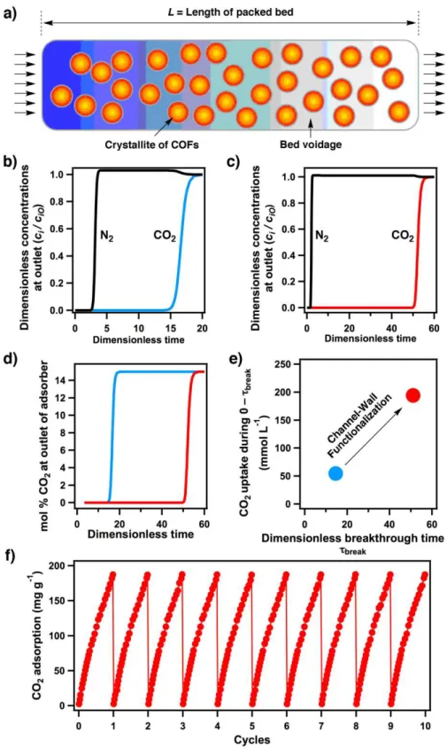
Figure 9. a) Fixed–bed adsorber for COFs. Flue gas breakthrough profiles of (b) [HO]100%-H2P-COF and (c) [HO2C]100%-H2P-COF at 298 K. d) Comparison of %CO2 at the adsorber outlet at 298 K (blue curve: [HO]100%-H2P-COF, red curve: [HO2C]100%-H2P-COF). e)
Comparison of CO2 capture productivity at 298 K (blue spot: [HO]100%-H2P-COF, red spot: [HO2C]100%-H2P-COF). f) Cycle test of [HO2C]100%-H2P-COF at 273 K.
[HO]100%-H2P-COF and [HO2C]100%-H2P-COF for the separation of a CO2/N2 mixture that is relevant for CO2 capture from flue gases and for my evaluation I assumed the CO2/N2 mixtures contained 15% CO2 and 85% N2, following the earlier work of Mason et al.[6l] Figures 8a and 8b show the IAST calculation of CO2 and N2 uptake capacities for the 15/85 CO2/N2 mixture at 298 K. Notably, [HO2C]100%-H2P-COF exhibited a CO2 uptake capacity of 0.51 mol kg–1 at 100 kPa (= 1 bar), whereas [HO]100%-H2P-COF displayed an uptake of only 0.16 mol kg–1 (Figure 8a). By contrast, [HO]100%-H2P-COF exhibited a N2 uptake of 0.118 mol kg–1, which is substantially greater than that of [HO2C]100%-H2P-COF (0.038 mol kg–1, Figure 8b). These results clearly suggest that the functionalization of channel walls with carboxylic acid groups significantly enhances the CO2 adsorption capacity of the flue mixture gas. Figure 9c presents the adsorption selectivity for the 15/85 CO2/N2 flue gas mixture, in comparison to those of CuBTC (a MOF),[6j] MgMOF-74,[6k-6n] and NaX zeolite.[6n,6o] At low pressures, such as 0.1 kPa, the adsorption selectivity Sads was 323, which is greater than that of both CuBTC (broken black curve) and NaX zeolite (broken blue curve) and is close to that of MgMOF-74 (broken green curve). By contrast, [HO]100%-H2P-COF exhibited a selectivity of only 18 at 0.1 kPa. At 100 kPa, [HO2C]100%-H2P-COF exhibited a selectivity of 77, whereas [HO]100%-H2P-COF exhibited a selectivity of only 8. Notably, the selectivity of [HO2C]100%-H2P-COF is sufficiently high for potential practical use.
To clarify the nature of CO2 adsorption, the isosteric heat of adsorption (Qst) was calculated from the CO2 adsorption isotherms measured at pressures up to 1 bar and at temperatures at 273 and 298 K. Interestingly, the Qst value increased proportionally with the carboxylic acid content (Table 3). Therefore, the functionalized walls facilitate interactions with CO2 and contribute to the enhanced performance. The Qst value was 43.5 kJ mol–1 for [HO2C]100%-H2P-COF, which is compatible to that for MgMOF-74 and much higher than those for [HO]100%-H2P-COF (34.5 kJ mol–1), CuBTC, and NaX zeolite.
To evaluate the gas separation ability of adsorbents under kinetic flowing gas conditions, breakthrough simulations were performed using a precise methodology established by Krishna and Long.[7b] These simulations properly reflect the separation capability of a pressure-swing adsorption (PAS) process, which is an energetically efficient method for industrial-scale capture. The performance of a COF in a PSA unit is governed by both selectivity and capacity factors. Figure 9a presents a schematic of a packed-bed absorber. Figures 9b and 9c show typical breakthrough curves for [HO]100%-H2P-COF and [HO2C]X%-H2P-COF, respectively. The x-axis is dimensionless time, defined as dividing the actual time, τ, by the characteristic time, L /µ. Clearly, [HO2C]100%-H2P-COF exhibited a breakthrough time of 50, which is much longer than that of [HO]100%-H2P-COF (15). Figure 9d compares the breakthrough characteristics of COFs in terms of mole% CO2 at the outlet as a function of dimensionless time for operation at a total pressure of 100 kPa. [HO]100%-H2P-COF (red curve) has a breakthrough time much longer than that of [HO]100%-H2P-COF (blue curve). Longer breakthrough times are desirable for greater CO2 capture. For a quantitative evaluation of the COFs, I arbitrarily chose the required outlet gas purity to be
<0.05 mol% CO2. Using this purity specification, I determined the breakthrough times, τbreak, for each COF. On the basis of the material balance on the absorber, I determined the amount of CO2
captured during the time interval 0-τbreak. Figure 9e presents a plot of the number of millimoles of CO2 captured per L of adsorbent during the time interval 0-τbreak against the breakthrough time τbreak. Notably, [HO2C]100%-H2P-COF (red circle) exhibited superior CO2 productivity compared with [HO]100%-H2P-COF (black circle).
The aforementioned results indicate that channel-wall functionalization is efficient to convert a conventional COF into outstanding CO2 adsorption materials; the effects of functional groups on carbon dioxide capture are positive and profound ranging from capacity to selectivity and productivity. To examine the cycle performance of [HO2C]100%-H2P-COF in terms of CO2 uptake, I conducted temperature and vacuum swings with a Belsorp mini II analyzer by saturating the samples with CO2 up to 1.0 bar at 273 K followed by placing the samples under high vacuum for 60 min at 353 K. Remarkably, after 10 cycles, no significant decline in uptake capacity was observed (Figure 9f), indicating complete desorption in each regeneration cycle and excellent cycling performance. These features assure a green process in regenerating the adsorbers.
Conclusion
In summary, I developed a strategy for converting a conventional 2D COF into an outstanding CO2 capture scaffold via channel-wall functionalization. The high-throughput ring-opening reaction is useful for creating carboxylic acid functionalized channel walls while retaining layered and open porous structure. Given the rather limited room for increasing the porosity of 2D COFs, together with the availability of a broad diversity of different functional groups, I anticipate that the present channel-wall engineering strategy will be critical to exploring 2D COFs for high-performance gas storage and separation.
Experimental Sections
Methods Fourier transform Infrared (FT IR) spectra were recorded on a JASCO model FT IR-6100 infrared spectrometer. UV-Vis-IR diffuse reflectance spectrum (Kubelka-Munk spectrum) was recorded on a JASCO model V-670 spectrometer equipped with integration sphere model IJN-727. Powder X-ray diffraction (PXRD) data were recorded on a Rigaku model RINT Ultima III diffractometer by depositing powder on glass substrate, from 2θ = 1.5° up to 60° with 0.02°
increment. Elemental analysis was performed on a Yanako CHN CORDER MT-6 elemental analyzer. TGA measurements were performed on a Mettler-Toledo model TGA/SDTA851e under N2, by heating to 800 °C at a rate of 10 °C min–1. Nitrogen sorption isotherms were measured at 77 K with a Bel Japan Inc. model BELSORP-mini II analyzer. Before measurement, the samples were degassed in vacuum at 120 °C for more than 10 h. By using the non-local density functional theory (NLDFT) model, the pore volume was derived from the sorption curve. 1H NMR spectra were recorded on a JEOL model JNM-LA400 NMR spectrometer, where the chemical shifts ( in ppm) were determined with a residual proton of the solvent as standard. Scanning electron microscopy (SEM) was carried out using solid samples on Hitachi Hitechnology C C model SU6600 and energy dispersive X-ray spectrometry (EDX) was recorded on Bruker AXS model using Quantax system with XFlash 610 detector.
Materials and Synthetic Procedures
1-Butanol, o-dichlorobenzene (o-DCB), anhydrous acetone (99.5%), tetrahydrofuran, and acetic acid were purchased from Wako Chemicals. succinic anhydride and 1,4-phthalaldehyde (PA)
was purchased from TCI. Free-base 5,10,15,20-tetrakis(p-tetraphenylamino) porphyrin (H2P) was prepared from p-nitrobenzaldehyde using a literature procedure.[9a] 2,5-Dihydroxyterephthala ldehyde (DHTA) was synthesized according to a reported method.[9b]
[HO]X%-H2P-COFs. An o-DCB/BuOH/6 M AcOH mixture (5/5/1 by vol.; 1.1 mL) of H2P (0.02 mmol, 13.48 mg) and DHTA/PA (total 0.04 mmol) at different molar ratios of 25/75, 50/50, 75/25, and 100/0 was degassed in a Pyrex tube (10 mL) by three freeze-pump-thaw cycles. The tube was sealed off and heated at 120 °C for three days. The precipitate was collected by centrifugation, washed with anhydrous THF for five times, and washed with acetone twice. The powder was dried at 120 °C under vacuum overnight to give the corresponding product in isolated yields of 78%, 75%, 84%, and 82% for [HO]25%-H2P-COF, [HO]50%-H2P-COF, [HO]75%-H2P-COF, and [HO]100%-H2P-COF, respectively.
[HO2C]X%-H2P-COFs. [HO]X%-H2P-COFs (30 mg) was weighed into a 10-mL glass vial, to which succinic anhydride (6 mL, 1.0 M solution in anhydrous acetone) was added. The reaction mixture was heated at 60 °C for two days. The precipitate was collected by centrifugation, washed with anhydrous THF for five times. The crude product was rinsed with THF for 48 h using a Soxhlet extractor. The powder was dried at 100 °C under vacuum overnight to give the corresponding products of [HO2C]25%-H2P-COF, [HO2C]50%-H2P-COF, [HO2C]75%-H2P-COF, and [HO2C]100%-H2P-COF, quantitatively.
Hydrolysis of [HO2C]X%-H2P-COFs. The [HO2C]X%-H2P-COFs (100 mg) sample were hydrolyzed by refluxing in a THF/H2O (2/1 by vol., 24 mL) solution of KOH (3 M) for 5 days. After filtration, 5 mL of aqueous HCl solution (6 M) was added slowly to the filtrate and the mixture was stirred for 1 h. The greenish porphyrin precipitate was removed by filtration. The filtrate was evaporated under vacuum and submitted to 1H NMR spectroscopy in d6-DMSO.
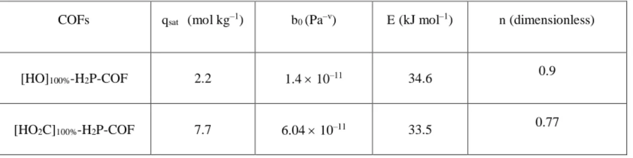
Fitting of pure component isotherms
The salient properites of two different COFs ([HO]100%-H2P-COF and [HO2C]100%-H2P-COF) are specified in Table 4. The potential of these COFs are evaluated for the separation of CO2/N2
mixtures that is relevant for CO2 capture from flue gases. For my evaluations, I assume the CO2/N2 mixtures to contain 15% CO2, and 85% N2, following the earlier work of Mason et al.[8a]
The experimentally measured excess loadings of CO2, and N2, obtained at different temperatures, were first converted to absolute loadings before data fitting. The procedure for converting to absolute loadings is the same as described in the Supporting Information accompanying the paper of Wu et al.[8b] For the purpose of converting to absolute loadings, the pore volumes used are specified in Table 5. The isotherm data for CO2 were fitted with the Langmuir-Freundlich model:
with T-dependent parameter b
The Langmuir-Freundlich parameters for adsorption of CO2 are provided in Table 6. The simpler Langmuir model was adequate for fitting the isotherm data for N2; Table S6 provides the T-dependent Langmuir parameters for N2 in different materials
Table 4. Salient properties of [HO]100%-H2P-COF and [HO2C]100%-H2P-COF (The crystal framework densities, required in the breakthrough simulations, are estimated as (bulk density)/(one-bed porosity) with the assumption that the bed porosity is 0.4)
COFs Bulk density (g cm–3) SBET (m2 g–1) Pore volume (cm3 g–1) Pore size (nm)
[HO]100%-H2P-COF 0.24 1186 0.78 2.54
[HO2C]100%-H2P-COF 0.26 326 0.49 1.56
Table 5. Langmuir-Freundlich parameters for adsorption of CO2 in COFs (The experimentally measured excess loadings were first converted to absolute loadings before data fitting.)
COFs qsat (mol kg–1) b0 (Pa–v) E (kJ mol–1) n (dimensionless)
[HO]100%-H2P-COF 2.2 1.4 10–11 34.6 0.9
[HO2C]100%-H2P-COF 7.7 6.04 10–11 33.5 0.77
Table 6. One-site Langmuir parameters for N2 in different materials
COFs qA,sat (mol kg–1) bA0 (Pa–1) EA (kJ mol–1)
[HO]100%-H2P-COF 1.2 6.14 10–12 30.7
[HO2C]100%-H2P-COF 2 2.38 10–11 23.9
2.4.4 Isosteric heat of adsorption
The isosteric heat of adsorption, Qst, defined as
(3)
was determined using the pure component isotherm fits using the Clausius-Clapeyron equation.
Qst RT2 ln p
T
q
2.4.5 IAST calculations
The selectivity of preferential adsorption of component 1 over component 2 in a mixture containing 1 and 2, perhaps in the presence of other components too, can be formally defined as
2 1
2 1
p p
q Sads = q (4)
In equation (4), q1 and q2 are the absolute component loadings of the adsorbed phase in the mixture. These component loadings are also termed the uptake capacities. In all the calculations to be presented below, the calculations of q1 and q2 are based on the use of the Ideal Adsorbed Solution Theory (IAST) of Myers and Prausnitz.[8c] The accuracy of the IAST calculations for estimation of the component loadings for several binary mixtures in a wide variety of zeolites, and MOFs has been established by comparison with Configurational-Bias Monte Carlo (CBMC) simulations of mixture adsorption.[8d-i]
2.4.6 Simulation methodology for transient breakthrough in fixed bed absorbers
The separation of CO2/N2 mixtures is commonly carried out in fixed bed absorbers in which the separation performance is dictated by a combination of three separate factors: (a) adsorption selectivity, (b) uptake capacity, and (c) intra-crystalline diffusivities of guest molecules within the pores. Transient breakthrough simulations are required for a proper evaluation of MOFs; the simulation methodology used in my work is described in earlier publications.[8j,8k] A brief summary of the simulation methodology is presented below.
Assuming plug flow of an n-component gas mixture through a fixed bed maintained under isothermal conditions (see schematic in Figure 9a), the partial pressures in the gas phase at any position and instant of time are obtained by solving the following set of partial differential equations for each of the species i in the gas mixture.[8l]
In equation (5), t is the time, z is the distance along the adsorber, r is the framework density, e is the bed voidage, v is the interstitial gas velocity, and
q
i( z t , )
is the spatially averaged molar loading within the crystallites of radius rc, monitored at position z, and at time t.At any time t, during the transient approach to thermodynamic equilibrium, the spatially averaged molar loading within the crystallite rc is obtained by integration of the radial loading profile
For transient unary uptake within a crystal at any position and time with the fixed bed, the radial distribution of molar loadings, qi, within a spherical crystallite, of radius rc, is obtained from a solution of a set of differential equations describing the uptake
The molar flux Ni of component i is described by the simplified version of the Maxwell-Stefan equations in which both correlation effects and thermodynamic coupling effects are considered to be of negligible importance
Summing equation (6) over all n species in the mixture allows calculation of the total average molar loading of the mixture within the crystallite
The interstitial gas velocity is related to the superficial gas velocity by
In industrial practice, the most common operation uses a step-wise input of mixtures to be separated into an absorber bed that is initially free of adsorbents, i.e. I have the initial condition
At time t = 0, the inlet to the absorber, z = 0, is subjected to a step input of the n-component gas mixture and this step input is maintained till the end of the adsorption cycle when steady-state conditions are reached.
where u0 is the superficial gas velocity at the inlet to the absorber.
The breakthrough characteristics for any component is essentially dictated by two sets of parameters: (a) The characteristic contact time between the crystallites and the surrounding fluid phase, and (b), that reflect the importance of intra-crystalline diffusion limitations. It is common to use the dimensionless time, obtained by dividing the actual time t, by the characteristic time, when plotting simulated breakthrough curves.
If the value of is large enough to ensure that intra-crystalline gradients are absent and the entire crystallite particle can be considered to be in thermodynamic equilibrium with the surrounding bulk gas phase at that time t, and position z of the adsorber
qi(t,z)=qi(t,z) (13)
The molar loadings at the outer surface of the crystallites, i.e. at r = rc, are calculated on the basis of adsorption equilibrium with the bulk gas phase partial pressures pi at that position z and time t. The adsorption equilibrium can be calculated on the basis of the IAST. The assumption of thermodynamic equilibrium at every position z, and any time t, i.e. invoking Equation (10), generally results in sharp breakthroughs for each component. Sharp breakthroughs are desirable in practice because this would result in high productivity of pure products. Essentially, the influence of intra-crystalline diffusion is to reduce the productivity of pure gases. For all the breakthrough calculations reported in this work, I assume negligible diffusion resistances for all materials and I invoke the simplified Equation (10).
Notation
bA dual-Langmuir-Freundlich constant for species i at adsorption site A, ci molar concentration of species i in gas mixture, mol m-3
ci0 molar concentration of species i in gas mixture at inlet to adsorber, mol m-3 L length of packed bed adsorber, m
N number of species in the mixture, dimensionless Ni molar flux of species i, mol m-2 s-1
pi partial pressure of species i in mixture, Pa pt total system pressure, Pa
qi component molar loading of species i, mol kg-1
)
,
( z t
q
i spatially averaged component molar loading of species i, mol kg-1rc radius of crystallite, m R gas constant, 8.314 J mol-1 K-1
t time, s
T absolute temperature, K
u superficial gas velocity in packed bed, m s-1 v interstitial gas velocity in packed bed, m s-1 Greek letters
e voidage of packed bed, dimensionless r framework density, kg m-3
time, dimensionless Subscripts
i referring to component ibreak referring to breakthrough t referring to total mixture
![Figure 1. a) Synthesis of [HO 2 C] X% -H 2 P-COFs with channel –walls functionalized with carboxylic](https://thumb-ap.123doks.com/thumbv2/123deta/6167724.105107/20.892.136.753.641.1069/figure-synthesis-ho-cofs-channel-walls-functionalized-carboxylic.webp)
![Figure 5. a) Nitrogen sorption isotherm curves of [HO] X% -H 2 P-COFs. b-e) Pore size and pore size](https://thumb-ap.123doks.com/thumbv2/123deta/6167724.105107/26.892.137.758.110.672/figure-nitrogen-sorption-isotherm-curves-cofs-pore-size.webp)
![Figure 1. FT-IR spectra of [HC C] x -H 2 P-COFs, [Et] x -H 2 P-COFs, [MeOAc] x -H 2 P-COFs,](https://thumb-ap.123doks.com/thumbv2/123deta/6167724.105107/50.892.142.741.115.1071/figure-ft-spectra-cofs-et-cofs-meoac-cofs.webp)
![Figure 2. Nitrogen sorption isotherm curves of [HC C] x -H 2 P-COFs (a, red: 25, blue: 50, green:](https://thumb-ap.123doks.com/thumbv2/123deta/6167724.105107/52.892.135.753.117.565/figure-nitrogen-sorption-isotherm-curves-cofs-blue-green.webp)