Rock magnetic study of basalt at Lonar
impact crater in India: Effects of stress
waves on rock magnetic properties
Itoyuki Nishioka
DOCTOR OF
PHILOSOPHY
Department of Polar Science
School of Multidisciplinary Sciences
The Graduate University for Advanced Studies
2007
Abstract
Magnetic anomaly data provide valuable information on size and morphology of buried impact craters. An understanding of how stress waves change mag- netic properties of rock is critical for correct interpretation of magnetic data. Although previous studies demonstrated effects of strong shock on magnetic properties of rocks beneath impact craters, effects of relatively weak shock for those of rocks in crater wall have been poorly studied. In this context, we investigated shock effects on magnetic properties through studies of experi- mentally impacted basaltic andesite, and basalt from natural impact crater (Lonar crater).
An initial peak pressure of 5 GPa was generated in a block of basaltic andesite containing Ti-rich titanomagnetite with the impact of a cylindrical projectile. Effects of decaying stress waves on magnetic properties were sub- sequently quantified. Natural remanent magnetization (NRM) was partially but significantly demagnetized at peak pressures higher than 1 GPa. High- coercivity part of NRM, even higher than 80 mT, was partially demagnetized. At higher pressure (3-5 GPa), low-field magnetic susceptibility was signifi- cantly reduced and coercivity was increased, probably due to increased inter- nal stress. Different patterns of change in anisotropy of magnetic susceptibility (AMS) were observed at different distance from the impacted surface. In high- pressure range (>3 GPa), the anisotropy degree was increased, the minimum susceptibility was oriented toward the shock direction, and the average suscep- tibility was decreased. This feature is consistent with the result of a previous shock experiment. The initial orientations of AMS were however significantly changed at around 0.4-3 GPa; The maximum susceptibility was induced par- allel to the shock direction, and superposed on the initial AMS. This kind of changes in the AMS parameters has been never reported.
Basalt samples were collected from flows in the crater wall, ejecta clasts, and flow outside the rim of Lonar crater. Irreversible thermomagnetic curves
and the maximum Curie temperature of 500-560◦C indicated presence of Ti- poor titanomagnetite and its oxidized phase as the main magnetic minerals in Lonar basalts. The result of AMS measurement of both inside and outside samples showed relatively weak anisotropy degree (P <1.03), which is similar to that of basalt from outside the crater rim. The samples from the crater wall showed predominantly oblate shape of AMS ellipsoid, with tightly clustered vertical distribution of the minimum principal axes. Substantial, but not strict, parallelism between the maximum principal axes and the radial direction from the crater center was observed only for the samples from the lower part of the crater wall. This fact and the result of the shock experiment indicate that radially expanding stress waves reoriented the initial AMS.
Stepwise thermal demagnetization of NRM and anhysteretic remanent mag- netization (ARM) demonstrated that the main NRM carriers of Lonar basalts are titanomagnetite and titanomaghemite. The primary NRM component was demagnetized above 200◦C, indicating that the post-impact temperature did not exceed the value. The site-mean and overall-mean directions were deter- mined for both the high and low coercivity components isolated by stepwise alternating field demagnetization. The intensities of the primary NRM com- ponent were generally decreased toward the lower altitude, and positively cor- related with the intensity of ARM after AFD with a peak field of 15 mT. This fact indicates that the NRM intensity is not simply a function of distance from the crater center as previously argued. Meanwhile, the site-mean directions of the low-coercivity NRM component were more tightly clustered before tilt correction, and the in-situ overall mean direction was not distinguishable with the present field direction. The ejecta samples also showed two NRM com- ponents, whose remagnetization circles intersected at an orientation close to the present earth field. These results suggest that the dominant fraction of the low-coercivity NRM component for the basalt flows in the crater wall and ejecta clasts were not shock remanent magnetization as previously suggested, but were viscous remanent magnetization acquired since the formation of the crater.
Parts of this thesis were published in Earth Planets and Space [Nishioka et al., 2007].
Acknowledgements
Initially, I would like to thank my supervisor, Prof. Minoru Funaki of National Institute of Polar Research (NIPR), for his support and guidance throughout the work.
Field trips in India were supported by a number of people. The efficient field logistics were set up by the Geological Survey of India (GSI). I especially thank Dr. K. Venkata Rao for his support and discussions on the various aspects of the research. I thank Dr. K. S. Mishra, Dy. Director General of GSI Central Region, for kindly guiding us at the crater and the surrounding area. I thank Dr. G. V. S. Poornachandra Rao of the National Geophysical Research Institute of India for helpful advice on the research at Lonar.
The shock experiment was conducted using a propellant gun installed at the National Institute for Material Science in Tsukuba. I thank Dr. Toshimori Sekine for his collaboration on the research, which have led to a new result regarding the AMS changes presented in this thesis.
I thank Prof. Yasuhiko Syono of Tohoku University for sharing his in- sights in rock magnetism and shock experiment. Comments and suggestions by Prof. Naoto Ishikawa of Kyoto University greatly helped to improve this thesis. Profs. Kazuo Shibuya, Yoshifumi Nogi, and Dr. Akira Yamaguchi of NIPR gave me helpful comments regarding my thesis and presentation slides. I also thank Profs. Viktor Hoffmann of University of T¨ubingen and Mituko Ozima for their valuable discussions on rock magnetic issues.
Contents
Abstract 1
Acknowledgements 3
Contents 4
Glossary 6
1 General Introduction 7
1.1 Geophysical signatures of impact craters . . . 7
1.2 Review of previous shock experiments . . . 8
1.3 Lonar impact crater . . . 10
1.4 Identification of SRM . . . 13
1.5 Purpose of the present study . . . 13
2 Shock experiment on basaltic andesite: Irreversible changes in magnetic properties 17 2.1 Experiments . . . 17
2.2 Initial mineralogy and magnetic properties . . . 22
2.3 Shock effects on magnetic properties . . . 23
2.3.1 Hysteresis parameters and NRM . . . 23
2.3.2 Coercivity spectra of the residual NRM . . . 25
2.3.3 Anisotropy of magnetic susceptibility . . . 27
2.4 Discussion . . . 27
2.5 Conclusions . . . 29
3 AMS of basalts from upper wall of Lonar crater 31 3.1 Geological setting . . . 31
3.2 Sampling . . . 33
3.3 Experiments . . . 34
Contents
3.4 Results . . . 35
3.4.1 Thermomagnetic curves . . . 35
3.4.2 Hysteresis parameters . . . 35
3.4.3 The average susceptibility and shape of AMS ellipsoids . 35 3.4.4 Orientations of the principal susceptibilities . . . 41
3.5 Discussion . . . 41
3.5.1 Identification of magnetic minerals . . . 41
3.5.2 AMS . . . 42
3.6 Conclusions . . . 45
4 NRM of Lonar basalt 46 4.1 Experiments . . . 46
4.2 Results . . . 47
4.2.1 Intensity of the primary NRM component . . . 49
4.2.2 Directional statistics . . . 50
4.3 Discussion . . . 57
4.3.1 Intensity of the primary NRM component . . . 57
4.3.2 Origin of the low-coercivity NRM component . . . 57
4.4 Conclusions . . . 58
5 Discussion 59 5.1 AMS: an alternative tool to study impact crater . . . 59
5.2 Possible cause of magnetic anomaly of Lonar crater . . . 60
6 Summary and Conclusions 62
References 64
Glossary
Abbreviations
AMS anisotropy of low-field magnetic susceptibility ARM anhysteretic remanent magnetization
AFD alternating field demagnetization
IRM isothermal remanent magnetization
MD multidomain
MDF median destructive field
NRM natural remanent magnetization
PSD pseudo-singledomain
SD singledomain
SRM shock remanent magnetization
TRM thermal remanent magnetization
VRM viscous remanent magnetization
Symbols
ARM15 [A m2/kg] intensity of ARM after AFD with a peak field of 15 mT
F AMS foliation (K2/K3)
Hc [mT] coercivity
Hcr [mT] remanence coercivity Is [A m2/kg] saturation magnetization
Ir [A m2/kg] saturation remanent magnetization
Kx (x=1,2,3) [m3/kg] the principal low-field magnetic susceptibilities (K1 > K2 > K3) Km [m3/kg] average low-field magnetic susceptibility (K1+ K2+ K3)/3 Kp [m3/kg] high-field magnetic susceptibility
L AMS lineation (K1/K2)
N RM15 [A m2/kg] NRM after AFD with a peak field of 15 mT
P degree of AMS (K1/K3)
Ps [GPa] shock pressure
Tc [◦C] Curie temperature
Chapter 1
General Introduction
1.1 Geophysical signatures of impact craters
Impact craters are dominant landform on many planets, satellites, or other solid body in the Solar System. In contrast, those on earth are less common due to erosion or burial by geologic process such as plate subduction, mountain building, sedimentation, or volcanism. Over 170 impact structures have so far been identified around the world according to Earth Impact Database [2008]. More than 30% of them are inaccessible to direct observation due to burial in post-impact sediments. Geophysical data played a central roll for the initial recognition of these hidden impact craters.
Terrestrial impact structures exhibit characteristic gravity and magnetic signatures [Pilkington and Grieve, 1992]. The most common is a circular grav- ity low (D<30 km), due to reduction in density by brecciation and post-impact sediment infill. The gravity signature can be modeled well using known mor- phometric parameters of impact structures. In contrast, magnetic signature is more varied due to larger variation in the magnetic properties of rocks. Magnetic modeling is often difficult due to lack of magnetization data and concepts on impact related magnetization. For example, the recent drilling project at the Bosumtwi impact structures in Ghana revealed magnetic prop- erties of rocks beneath the crater floor [Elbra et al., 2007]. Although a previous magnetic modeling had predicted presence of highly magnetized body, such material was not recovered.
Detailed intensity distributions of remanent magnetization of the lunar [Halekas et al., 2002] and Martian [Acu˜na et al., 1999] surface were mapped using magnetic field data derived from satellite observations. One of the re-
Chapter 1. General Introduction
100
Temperature (°C) 227 Pressure (GPa)
2 1 20 8
427 D=1.5 km
Figure 1.1: Maximum pressure (right) and temperature (left) calculated for a 1.5 km diameter impact crater formed in granite, modified after Ugalde et al. [2005].
markable features was demagnetized areas around impact craters or basins. The demagnetized area extend to 2−4 crater radii on the moon [Halekas et al., 2002] and 1.4 radii on Mars [Mohit and Arkani-Hamed, 2004]. The magnetic lows inside the structures was interpreted as results of thermal demagneti- zation of crustal rocks; i.e., post-shock temperature increase and subsequent cooling in absence of external field. However, thermal demagnetization could not explain the magnetic lows at outside the crater rim. Shock demagnetiza- tion was suggested as the cause, referring to the results of laboratory impact experiments described below.
1.2 Review of previous shock experiments
Before reviewing earlier shock experiments, shock pressure and temperature involved in cratering process should be mentioned. A hypervelocity impact of projectile generates shock waves in both the projectile and the target. The shock wave essentially decays concentrically in the target. By the shock com- pression, the target is heated to a certain post-shock temperature, which in- creases with increasing shock pressure. The most of the projectile and the target near the impact is largely transformed to melt and vapor (>50 GPa). Beyond the regions where the target is vaporized and melted, target material will be shock metamorphosed (>5 Gpa) or fractured. Many of the vaporized, molten, and shock-metamorphosed materials are ejected from the transient cavity. Some of the ejected materials fall back to the ground. Fig. 1.1 illus-
Chapter 1. General Introduction
trates estimated peak pressures and temperatures around final crater with a diameter of 1.5 formed in granite.
In many of previous shock experiments, igneous rocks containing titano- magnetite with variable Ti content were used as targets. Shock pressures were produced using various techniques: impact of high-velocity projectiles [Har- graves and Perkins, 1969; Pohl et al., 1975; Cisowski and Fuller, 1978], explo- sives [Pesonen et al., 1997; Gattacceca et al., 2007], or laser [Gattacceca et al., 2006]. Although the peak shock pressures of the above experiments ranged from 0.25 to 35 GPa, some of the early studies [Hargraves and Perkins, 1969; Cisowski and Fuller, 1978] did not provide accurate estimates of the pressure. The primary results of shock on magnetized igneous rocks are demagneti- zation of the primary remanence. With increasing shock pressures, larger in- tensity [Cisowski and Fuller, 1978] and higher-coercivity fraction [Pohl et al., 1975] of remanence is demagnetized. Significant portions of isothermal re- manent magnetization (IRM) and thermal remanent magnetization (TRM) of basalt were demagnetized already at shock pressure of 0.25 GPa [Pohl et al., 1975] and IRM was completely demagnetized at 2 GPa [Gattacceca et al., 2006]. In contrast, NRM of basalt was unaffected at shock pressures below 7 GPa [Gattacceca et al., 2007], which indicate NRM is much more resistant to shock than IRM.
In the presence of external field, the shocked igneous rocks were also remag- netized parallel to the field direction [Pohl et al., 1975; Cisowski and Fuller, 1978]. This soft component is often referred to as shock remanent magnetiza- tion or SRM. The intensity of SRM in the pressure range of at least 0.25−1 GPa is a function of shock pressure [Pohl et al., 1975]. Relationship between stability of SRM and shock pressure is unknown.
Low-field susceptibility is decreased and coercivity is increased by shock [Hargraves and Perkins, 1969; Pesonen et al., 1997; Gattacceca et al., 2007]. Degrees of these changes for diabase samples containing Ti-poor titanomag- netite were increased with increasing pressure up to 35 GPa [Pesonen et al., 1997]. Similar changes were induced in basalt containing Ti-rich titanomag- netite at shock pressures above 7 GPa [Gattacceca et al., 2007]. Decrease in magnetic susceptibility was also observed for granodiorite at a nuclear test site [Hargraves and Perkins, 1969].
Gattacceca et al. [2007] demonstrated that explosive-driven shocks of about 10 GPa on basalt and microdiorite acted to change their anisotropy of low-field magnetic susceptibility (AMS) as shown in Fig. 1.2. The degree of AMS was
Chapter 1. General Introduction
Figure 1.2: Effect of explosive-driven shock on AMS of basalt [Gattacceca et al., 2007]. (a) Degree of anisotropy of magnetic susceptibility vs. distance to the explosion. Pre-shock average is indicated by dashed line with one stan- dard deviation (grey bands). (b) Lower-hemisphere equal area projection of minimum principal axis (K3). The sample numbers correspond to the depth in mm.
increased near the shock surface, and the minimum principal susceptibilities were reoriented toward the shock direction. The AMS of terrestrial rock is usually controlled by the preferred orientation of magnetic minerals related to the primary formation of the rock or later tectonic deformation. The result of the experiment indicates that meteorite or rocks from impact craters might not exhibit the primary AMS.
1.3 Lonar impact crater
Lonar crater is located in central India (19◦59’N, 76◦31’E) as shown in Fig 1.3). The crater is nearly circular and has a rim-to-rim diameter of 1.8 km (Fig. 1.4 and Fig. 1.5). The formation age was estimated to 50,000 years ago or earlier [Storzer and Koeberl, 2004]. We believe that Lonar crater has several features that make the crater significant to study shock effects on rock magnetic prop- erties: (1) good surface exposure of the basalt flows in the crater wall; (2) minimum alteration of basalt since the formation of the crater; (3) presence of extensive paleomagnetic studies of Deccan Traps, which provide informa- tion on magnetic properties and NRM components of unshocked basalts; (4) a closer analogy to the impact structures on basaltic crust on Mars.
Earlier studies [Cisowski and Fuller, 1978; Poornachandra Rao and Bhalla,
Chapter 1. General Introduction
Nagpur Bombay
Bay of Bengal
0 400 km
Arabian Sea
72° 76°
12° 16°
Hyderabad Lonar
Deccan Traps
80° 84° 88°
20° 24°
12° 16° 20° 24°
72° 76° 80° 84° 88°
Figure 1.3: Map of India showing the location of Lonar. Deccan Traps are indicated by shaded area (Modified after Mahoney [1988]).
1984] isolated two NRM components from the basalts flows in the crater wall. The stable NRM component is likely the primary remanence of Deccan basalts, while the soft NRM component is oriented close to the present earth field direc- tion. Poornachandra Rao and Bhalla [1984] reported that the NRM intensity is decreased toward the crater center and soft NRM component is larger in the lower flows. Based on these observations and the results of the shock exper- iments mentioned above, they suggested shock demagnetization and remag- netization of Lonar basalts; i.e., More reduced NRM near the crater center is due to stronger shock pressures, and SRM was acquired preferentially in the lower flows due to the relative abundance of low-coercivity grain. Lonar basalt exhibits high K¨onigsberger ratio (>1.0). If the suggestions (shock de/re- magnetization) would be correct, magnetic anomalies that extending out of the crater rim would be observed in a future study. This possibly explains the magnetic anomalies of impact structures on the moon or on Mars described above.
Chapter 1. General Introduction
Figure 1.4: Satellite image of Lonar crater.
Figure 1.5: Panoramic view of Lonar crater from the eastern rim.
Chapter 1. General Introduction
1.4 Identification of SRM
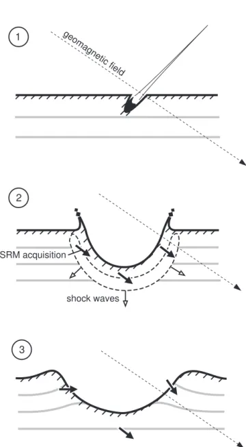
The fold test of overturned or tilted strata in the crater wall may be a unique method to detect SRM [Cisowski and Fuller, 1978]. The impacting meteorite penetrates the target rocks and releases its kinetic energy, generates shock waves (Fig. 1.6). The shock wave in the target expands downward and lat- erally, and weakens as it expands. The shock wave is detached because the rarefaction from the rear of the projectile encroaches [Melosh, 1989]. SRM is supposedly acquired simultaneously at the release from the shock pressure. Af- ter the passage of the shock and rarefaction waves, a residual particle velocity is imparted to the material, which marks the beginning of the excavation flow. The initial uplifting of the crater rim is continuation of the processes that ex- cavated the crater. Therefore fold test should be positive if the low-coercivity component is related to shock.
There are a few possible explanations that the tilted strata did not gravita- tionally collapse to the pre-impact horizontal positions. Kumar [2005] observed various types of impact-induced fractures in the upper wall of Lonar crater. These fractures may cause bulking of the flow sequence below the crater rim [Collins et al., 2004]. In addition to the in-situ brecciation, deep drilling at the rim of Meteor Crater in Arizona demonstrated that the fragments of the target and meteorite are horizontally injected in the wall rocks. It is however not clear that such debris dikes are present beneath the rim of Lonar Crater.
The flows in the upper walls of Lonar crater are generally tilted outward, with the average dips of 10◦−30◦. The dips are steepest near the rim, and become gentler as the distance from the rim is increased. Flow sequence of Deccan Traps is generally flat lying with dips of 1◦ or less [Mahoney, 1988]. Thus the tilting is obviously related to impact-induced structural uplifting. The average height of the present rim crest from the surrounding ground sur- face is 30 m, of which about 25 m is due to structural uplift and 5 m is due to upturned ejected debris [Fudali et al., 1980]. The exceptionally steep dipping (50◦−70◦) in the north-eastern wall was probably formed by slumping of the wall of the transient cavity during the crater modification stage [Kumar, 2005].
1.5 Purpose of the present study
Presence of possible giant impact crater(s) in Wilkes Land in East Antarctica was deduced from gravity data derived from the GRACE observations [von
Chapter 1. General Introduction
1
2
shock waves SRM acquisition
3
geoma gnetic
field
Figure 1.6: Schematic illustrations showing simple crater formation and acqui- sition of SRM (shock remanent magnetization).
Chapter 1. General Introduction
Frese et al., 2006]. A circular positive anomaly found in this region is analogous to those at large impact basins on Mars. The sub-ice sheet topographic peak ring surrounding the anomaly has a diameter of approximately 500 km, which is larger than the diameter of Chicxulub Crater (∼180 km) in the Yucatan Peninsula formed at the Cretaceous-Tertiary boundary. Multiple impacts in wide area of Wilkes Land were also suggested based on the presence of multiple ring-shaped structures in aeromagnetic and satellite gravity data [Weihaupt and Rice, 2007]. Confirmation of the impact origin is critical from the aspects of biological evolution on earth, as impact of large meteorites should impact on the global environment.
In order to correctly interpret the magnetic data, it is required to have a basic concept of how shock affects magnetic properties of surrounding rocks. Several studies revealed possible shock effects on magnetic properties of highly shocked materials in central part of crater, e.g., shock remanence [Halls, 1979], demagnetization [Robertson and Roy, 1979], and random orientation of NRM vector [Carporzen et al., 2005]. In contrast, magnetic properties of less shocked material in crater wall remains poorly studied, probably in part due to limited exposure of rocks at many terrestrial impact craters. However, as already men- tioned, the magnetic anomaly maps of the lunar and Martian surface indicate probable shock effects on rocks even beyond crater rims.
This thesis investigates effects of relatively weak shock on various magnetic properties through laboratory shock experiments and study of Lonar impact crater. Gattacceca et al. [2007] described the changes in magnetic properties of various types of rocks due to decaying stress waves with the initial peak pressures of 30 GPa. The pressure estimate is, however, less secure in the lower pressure range (<5 GPa), which is expected for the material in the crater wall. Thus we first describe shock effects on several magnetic properties in this pressure range. Magnetic properties of basalts in the crater wall of Lonar crater are then described.
The main body of this thesis is composed of three parts found in Chapter 2, 3, and 4. Chapter 2 describes the result of the shock experiment. Initial shock pressure of 5 GPa was generated in a basaltic andesite block; The effects of the decaying stress waves on NRM, low-field magnetic susceptibility, hys- teresis, and AMS were subsequently measured. The present study aimed to describe changes in magnetic properties with more accurate pressure estimate. Chapter 3 and 4 mainly describe the results of magnetic study of basalt from Lonar impact crater in India. In Chapter 3, magnetic mineralogy, hysteresis
Chapter 1. General Introduction
properties, and AMS are studied for the target rocks in the crater rim. In Chapter 4, shock effects on NRM were evaluate via tilt correction of the flows in the crater wall and detailed investigation of magnetic properties.
Chapter 2
Shock experiment on basaltic
andesite: Irreversible changes in
magnetic properties
2.1 Experiments
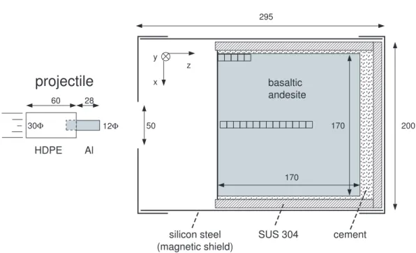
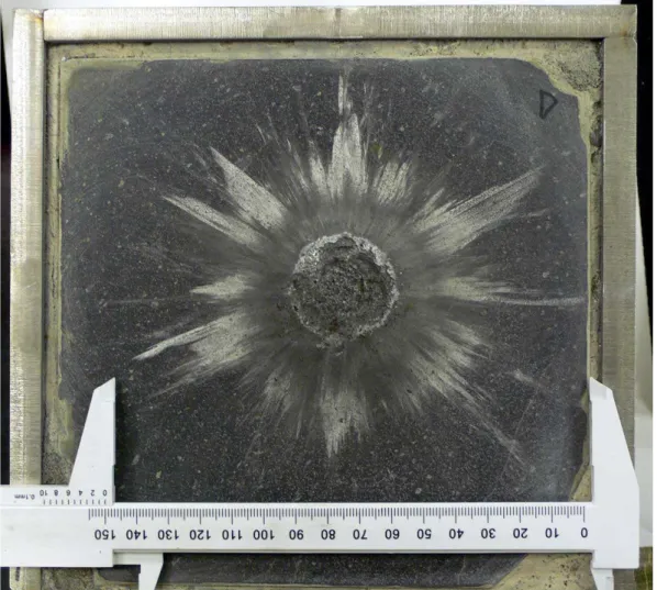
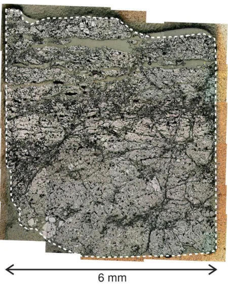
Stress waves were produced in the rock target using a single-stage propel- lant gun (30 mm bore) housed at the National Institute for Materials Science, Japan. The target was a cubic block of basaltic andesite (17 × 17 × 17 cm) housed in a stainless steel (SUS 304) container (Fig. 2.1). The target was fur- ther covered by silicon steel plates; The measured field intensity on the impact surface was 0.002 mT. A cylindrical aluminum projectile with a diameter of 11.75 mm and length of 38 mm (weight, 46.0 g) was set on a high-density polyethylene sabot. The projectile was accelerated to an impact velocity of 0.725±0.25 km/s to produce an initial pressure of 5.2±0.2 GPa, as determined using the impedance match method. We used the Hugoniot data for aluminum in Marsh [1980] and that for basalt in Nakazawa et al. [1997]. The duration of such a compression is considered to be in the order of microseconds [Nakazawa et al., 2002]. The projectile impacted near the center of the target surface. The target remained intact except for the formation of a shallow surface crater (3 cm diameter and 2 mm depth) as shown in Fig. 2.2. We observed many tensile cracks parallel to the impacted surface in the regions between the crater floor and a depth of 3 mm (Fig. 2.3). Subvertical cracks and local fractures were observed at deeper levels within the target.
We prepared 14 continuous cubic specimens (6 × 6 × 6 mm) from directly
Chapter 2. Shock experiment on basaltic andesite: Irreversible changes in magnetic properties
projectile
HDPE Al
12Φ
basaltic andesite
170
170 x
y z
60 28
30Φ 50
295
200
SUS 304 silicon steel
(magnetic shield)
cement
Figure 2.1: Schematic views of the projectile and the target.
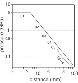
beneath the center of the crater floor; i.e. down to a depth of about 10 cm (Fig. 2.1). The specimens were numbered i01, i02, i03, etc., starting at the up- permost specimen. Five control specimens of the same size, which we assumed to be less shocked than the specimens from the central area, were cut from the side part of the target block (at 8 cm distance from the crater center, in the region near the impact surface). Pressure decay beneath the impact point was estimated after Nakazawa et al. [2002], whose planar shock experiments on basalts revealed that the relationship between the measured peak pressure, Ps, and the distance beneath the impact surface, x, can be formulated as follows:
Ps/P0 =
1 (x ≤ r),
(x/r)−1.7 (x > r).
where P0 is the initial pressure and r is the projectile radius. These equations were used in the present study to obtain estimates of the pressure ranges for each specimen (Fig. 2.4).
AMS was measured at room temperature (25◦C) using an AGICO KLY-3S Kappabridge. The operating frequency and field intensity were 875 Hz and 0.4 mT, respectively. AMS was measured before and after two-axis tumbling alternating field demagnetization (AFD) in a peak field of 80 mT. The average low-field susceptibility, Km, was calculated as Km = (K1+ K2+ K3)/3, where
Chapter 2. Shock experiment on basaltic andesite: Irreversible changes in magnetic properties
Figure 2.2: Impact crater formed on the surface of the basaltic andesite target.
Chapter 2. Shock experiment on basaltic andesite: Irreversible changes in magnetic properties
Figure 2.3: Reflected-light micrograph of specimen i01. The upper base is the crater floor. The homogeneous gray areas in the upper half of the specimen are epoxy-filled cracks.
Chapter 2. Shock experiment on basaltic andesite: Irreversible changes in magnetic properties
0.1
1
10
2 5
10
20 50100
distance (mm)
pr ess ur e (GP a)
0102 03
04 05
06-14 5
0.5
Figure 2.4: Pressure decay beneath the impact point as a function of distance from the surface (see text for equations).
K1, K2, and K3 are the principal susceptibilities (K1≥K2≥K3). The shapes of the AMS ellipsoids were characterized in terms of a shape parameter, T , and anisotropy degrees, P′, after Jelinek [1981].
T = (2η2−η1−η3)/(η1−η3)
P′ = expp2[(η1−ηm)2+ (η2−ηm)2 + (η3−ηm)2] where
η1 = lnK1, η2 = lnK2, η3 = lnK3, ηm = (η1+ η2+ η3)/3
We also measured hysteresis curves of the same specimens at room temperature with a maximum field of 1.0 T and using a vibrating sample magnetometer (Riken Denshi, BHV-50). The average hysteresis parameters for each specimen were calculated as (Ap+ 2 × An)/3, where Ap and Anare the hysteresis param- eters measured parallel and perpendicular to the shock direction, respectively.
Chapter 2. Shock experiment on basaltic andesite: Irreversible changes in magnetic properties
Table 2.1: Magnetic hysteresis parameters of basaltic andesite from Mt. Omuro at room temperature.
Hc (mT) Hcr (mT) Is (Am2/kg) Ir (Am2/kg) Kp (m3/kg)
9.5 21.0 0.50 0.12 2.29E-07
Notes: Coercivity, Hc; remanence coercivity, Hcr; saturation magnetization, Is; saturation remanence, Ir; and high-field magnetic susceptibility, Kp.
2.2 Initial mineralogy and magnetic proper-
ties
The target rock was sampled from Quaternary lava flows at Mt. Omuro, Izu Peninsula, Central Japan. The bulk density of the basaltic andesite, as mea- sured from a cylindrical core, was 2.74 g/cm3. This value is similar to those (2.63 to 2.74 g/cm3) recorded for basalts used in previous shock attenuation experiments [Nakazawa et al., 2002]. The petrology and mineralogy of Omuro basaltic andesite was described in Hamuro [1985]. The sample contains phe- nocrysts of olivine and plagioclase in a groundmass of plagioclase, augite, or- thopyroxene, pigeonite, and titanomagnetite.
A reversible thermomagnetic curve in a vacuum (∼ 10−3 Pa) up to 600◦C was obtained using the vibrating sample magnetometer (Fig. 2.5). A single Curie point at 180◦C indicates presence of Fe2.4Ti0.6O4 or TM60 [Akimoto et al., 1957]. Magnetic hysteresis parameters at room temperature after slope correction are shown in Table 2.1. Titanomagnetite content was estimated to be 1.1 vol.% based on a saturation magnetization (Is) of 125 kA/m expected for stoichiometric TM60 [Dunlop and ¨Ozdemir, 1997]. A comparison of ob- tained ratios of saturation magnetization to saturation remanence (Is/Ir) and remanence coercivity to coercivity (Hcr/Hc) with data presented by Day et al. [1977] indicates that the present values correspond to a grain size of 3 to 6 µm of crushed TM60. Under the optical microscope, titanomagnetite grains are observed to be 20 µm in size or smaller. The average ferromagnetic con- tribution to low-field susceptibility (Cf) was determined to be 96% using the following equation:
Cf = (Km−Kp)/Km
where Kp is high-field susceptibility calculated from the slope between 0.7 and
Chapter 2. Shock experiment on basaltic andesite: Irreversible changes in magnetic properties
0 0.1 0.2 0.3 0.4 0.5 0.6
0 100 200 300 400 500 600
magnetization (Am2 /kg)
temperature (°C) heating cooling
Figure 2.5: Thermomagnetic curve in vacuum.
1.0 T in the hysteresis loop.
2.3 Shock effects on magnetic properties
2.3.1 Hysteresis parameters and NRM
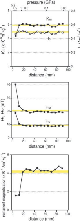
The target between the depths of 10 and 100 mm showed no systematic change in Km (Fig. 2.6, upper); the average value and standard deviation was 5.97 ± 0.14 (×10−6 m3/kg), similar to the values obtained for the side specimens (not shown; 5.95 ± 0.11 × 10⁻⁶ m3/kg). Km was reduced by about 30% in areas close to the impact (i01) relative to areas in the lower part of the specimen. In contrast, saturation magnetization, Is, was unaffected by the impact. The average Isvalue of the beneath-crater specimens was 0.49 ± 0.02 Am2/kg. The patterns of variations in Km and Is are similar among the lower specimens. Therefore, the Km values of specimens i02 to i14 did not show a significant decrease: their minor variations reflect heterogeneity in the volume density of magnetic grains. The decrease in Km recorded for the uppermost specimen (i01) was associated with the impact.
Coercivity, Hc, and the coercivity of remanence, Hcr, are generally con- stant for the lower specimens between i05 and i14, with average values of 9.0 and 19.5 mT, respectively (Fig. 2.6, middle). These parameters increased by
Chapter 2. Shock experiment on basaltic andesite: Irreversible changes in magnetic properties
Km(x10-6 m3 kg-1 )
distance (mm)
Is (Am2 kg-1 )
40
30
20
10
0
100 80 60 40 20 0
distance (mm) Hcr
Hc
Hc, Hcr(mT)
pressure (GPa)
5.2
Km
Is 8
6
4
2
0
100 80 60 40 20 0
0.8
0.6
0.4
0.2
0
5 1 0.5 0.1 0.05
6
4
2
0 remanent magnetization (x10-4 Am2 kg-1 )
100 80 60 40 20 0
distance (mm)
Figure 2.6: Post-impact magnetic parameters of the target rock as a function of the distance from the impacted surface toward the center of the specimen. Low-field magnetic susceptibility, Km; saturation magnetization, Is; coercivity, Hc; and remanence coercivity, Hcr; natural remanent magnetizaiton, NRM. Yellow bands indicate one standard deviation uncertainty for five specimens from the side of the block.
Chapter 2. Shock experiment on basaltic andesite: Irreversible changes in magnetic properties
5
4
3
2
1
0
80 70 60 50 40 30 20 10
-1-4
remanent magnetization (x 1 0 Am kg )
0field (mT)
i01
i02
i03
i04 i14
Figure 2.7: Alternating field demagnetization of specimens i01, i02, i03, i04, and i14.
approximately 100% for specimen i01, and to a lesser extent for specimen i02 and possibly i03.
The primary NRMs of samples between i03 and i14 appear to have been unchanged by the impact, while those of i01 and i02 were partially demag- netized (Fig. 2.6, lower). The increase of NRM for i02 after AFD (5 mT) is due to removal of soft component, which is likely shock-related remanence. In contrast, NRM intensity of i01 was unchanged after AFD (5 mT); i.e. no SRM was acquired and the primary low coercivity remanence was completely shock-demagnetized.
2.3.2 Coercivity spectra of the residual NRM
NRM of a wide range of coercivity were demagnetized by the impact (Fig. 2.7). The decay curves of specimens i01 and i02 remained lower than those of the less shocked specimens even after the demagnetization at a peak field of 80 mT. However, demagnetization appears especially significant in the low-coercivity range (0-10 mT). The decay curve of specimen i01 was flattened in this field range due to complete demagnetization of the initial NRM. Demagnetization of the low coercivity fraction is also indicated for specimen i03.
Chapter 2. Shock experiment on basaltic andesite: Irreversible changes in magnetic properties
i04
i04 i03
i03 i02
i02
i01
i01 i01
2 i03
4 1.02 1.04 1.06 1.08 1.10
-1.0 0.0 1.0
i01
i02 i03
i04 i05
anisotropy degree (P')
shape parameter (T)
prolate oblate
i01
i03 i04
i02
i04 i02
i03
i01
i03 i04 i02 i01
1.02 1.04 1.06 1.08 1.10
-1.0 0.0 1.0
i01
i02 i03 i04 i05
anisotropy degree (P')
shape parameter (T)
prolate oblate
(a)
(b)
K1 K2 K3
X
X
Y
Y
Figure 2.8: AMS parameters of the target rock (a) before and (b) after tum- bling AFD with a peak field of 80 mT. The solid and open symbols denote data from specimens located beneath the impact point and from the side of the target block, respectively. Left: Lower-hemisphere equal-area projection showing the orientations of the principal susceptibility axes. The vertical is the shock direction. Numbers denote specimen ID. The trajectories of the principal susceptibility axes before and after AFD are also shown. Right: plot showing the shape of the AMS ellipsoids. Anisotropy degree, P′, and shape parameter, T , are after Jelinek [1981].
Chapter 2. Shock experiment on basaltic andesite: Irreversible changes in magnetic properties
2.3.3 Anisotropy of magnetic susceptibility
The orientations of the principal susceptibility axes are shown in Fig. 2.8 (left). Those of the side specimens show tightly clustered triaxial distributions, but the specimens from beneath the impact point show a wider distribution. The inclinations of the minimum axes of specimens from beneath the impact point are generally shallower than the primary directions. The changes are most remarkable for specimens located close to the impact (i02 to i04), for which the easy (K1) axes are subparallel to the shock direction. In contrast, specimen i01 has the K3 axis oriented close to the shock direction. Figure 2.8a (right) reveals that the AMS of the side and lower specimens shows slightly oblate (T >1) AMS ellipsoids, with P′values of about 1.05. The side specimens record only minor variations in the AMS shape parameters. The AMS ellipsoids show a gradual change in shape with increasing pressure. The shifts in the data points are more pronounced close to the impact point (i01 to i05), and specimen i01 records a high P′ value. These results indicate that the observed changes in the shape, degree, and orientation of the AMS ellipsoids occur at lower pressure relative to that leading to a reduction in Km.
The principal susceptibility axes of the side specimens showed no signifi- cant change in orientation or shape of AMS ellipsoids following AFD (2.8b); in contrast, the specimens sampled from directly beneath the impact showed a general change in their AMS parameters. The average orientations of the principal axes of the samples from directly beneath the impact changed to ori- entations similar to those of the side specimens. The lower specimens showed no significant changes in T and P′ following AFD; however, remarkable shape changes were observed for specimens sampled from close to the impact.
2.4 Discussion
Increase in coercivity and decrease in low-field susceptibility was observed for the target just beneath the impact. Similar phenomenon was previously re- ported for uniaxially compressed magnetite-bearing sandstones [Jackson et al., 1993]. The above observations can be interpreted as magnetostrictive effect of titanomagnetite caused by increased internal stresses [Syono, 1965]. Re- duction in effective grain size of titanomagnetite is probably insignificant as a cause of the observed features, because susceptibility is probably a grain size independent parameter [Heider et al., 1996]. The results of the present exper-
Chapter 2. Shock experiment on basaltic andesite: Irreversible changes in magnetic properties
i02 i03
i04 i02
i03
i04 i02 i04
i03
X
Y
Figure 2.9: A lower-hemisphere equal-area projection showing the orientations of the principal susceptibility axes for specimens i02 to i04, after isolation of the shock-induced component. Symbols are the same as those for Fig. 3 (left).
iment also showed that shock changes the initial coercivity more sensitively than susceptibility. This is probably because coercivity, unlike susceptibility, is related to irreversible magnetization processes [Heider et al., 1996]; i.e., the pinning and unpinning of domain walls at lattice defects.
The observed AMS changes can be classified into the following three levels: (1) low shock pressure of less than 0.4 GPa (specimens i05 to i14) that in- duced only minor changes in the directions and shapes of the AMS ellipsoids; the shock effects were removed by tumbling AFD; (2) intermediate shock pres- sure ranging from 0.4 to 3 GPa (i02 to i04) that produced K1 axes oriented subparallel to the shock direction; tumbling AFD partly remove this effect; and (3) high shock pressure of greater than 3 GPa (i01) that gave rise to a significant increase in P′ and decrease in Km; the K3 axis changed from the initial direction to the shock direction, and the new AMS was highly stable against AFD. Gattacceca et al. [2007] observed similar changes in AMS for basalt and microdiorite shocked to pressure greater than 10 GPa.
The changes observed at low to intermediate shock pressures are generally similar to those reported from experiments involving static loading. Kapicka [1988] reported that the elastic deformation of basalt arising from uniaxial stresses up to 60 MPa caused essentially reversible changes in AMS. This result indicates that the magnetic domains are ordered when subjected to the external stress, but revert to the initial configuration with release of the stress [Appel and Soffel, 1985]; however, small irreversible changes in AMS do
Chapter 2. Shock experiment on basaltic andesite: Irreversible changes in magnetic properties
occur [Kapicka, 1983], probably related to pinning of domain walls at lattice defects or the irreversible rotation of spontaneous magnetization to other easy axes. Such stress-induced anisotropy has been suggested to be removable by tumbling alternating field demagnetization [Park et al., 1988]. In contrast, the AMS changes recorded at intermediate to high shock pressures may be related to either the fracturing of magnetic grains Gattacceca et al. [2007] or the formation of lattice defects such as dislocations. The both mechanisms are consistent with the high stability of the AMS changes against AFD (2.8b). We confirmed via optical microscopy that grain rotation is not responsible for the AMS changes.
The lack of exact parallelism between the K1 axes and the shock direction for the intermediate-pressure specimens can be explained by the effect of the primary AMS. We introduce a simple model in which the measured AMS (F1) represents the superposition of primary (F0) and shock-induced (Fs) AMS, each represented as second-rank symmetric tensors. In this case, Fs is easily determined by subtracting F0 from F1. We used the average tensor of the five side specimens as F0. Figure 2.9 shows that specimens i02 to i04 exhibit enhanced parallelism of the K1 axes after isolation of the shock components. We do not presently have a theoretical model to explain the K1 axes oriented parallel to the shock direction.
2.5 Conclusions
Irreversible changes in magnetic properties by stress waves were studied for basaltic andesite containing Ti-rich titanomagnetite. The result can be sum- marized as follows.
(1) AMS was induced in the pressure range higher than 0.4 GPa. The shock- induced AMS has K1 axis coaxial to the shock direction at 0.4-3 GPa. In contrast, K3 axis was reoriented toward the shock direction at 3-5 GPa. The anisotropy degree was significantly increased at 3-5 GPa.
(2) Coercivity was increased and susceptibility was decreased at 3-5 GPa. These changes are probably attributed to increased residual stress in titanomagnetite.
(3) Natural remanent magnetization (NRM) was partly demagnetized and remagnetized at 1-5 GPa. The low-coercivity fraction of NRM (< 5
Chapter 2. Shock experiment on basaltic andesite: Irreversible changes in magnetic properties
mT) was completely demagnetized or remagnetized, and high-coercivity fraction (10-80 mT) was partly demagnetized. Approximately 35% of the initial NRM survived at 3-5 GPa.
Chapter 3
AMS of basalts from upper wall
of Lonar crater
3.1 Geological setting
Lonar is located in the Buldana District of Maharastra State in India (19◦59’N, 76◦31’E as shown in Fig 1.3). Lonar crater is a circular, bowl shaped depression with a rim-to-rim diameter of 1.8 km. The average elevation of the rim crest is about 590 m, whereas that of the floor level is 470 m. The crater floor is occupied with shallow saline lake. The previous drillings through the crater floor revealed the presence of brecciated and pulverized basalt, overlain by post-impact sediment with maximum thickness of about 100 m [Fredriksson et al., 1973].
Findings of maskelynite [Fredriksson et al., 1973], shutter cones [Fredriks- son et al., 1973], tektite like bodies [Murali et al., 1987], and molten rocks [Osae et al., 2005] confirmed the impact origin of Lonar crater. However, type of impactor that formed the crater is unknown. Lonar is one of the youngest terrestrial impact craters along with Meteor Crater in Arizona; Formation age of Lonar has been estimated between 15 and 53 ka [Storzer and Koeberl, 2004, and references therein].
As already mentioned, the crater excavated the basalt flows of Deccan Traps. The main eruptions occurred around 65−67 Ma [Vandamme et al., 1991] during the passage of Indian continent over the Reunion Hotspot. The eruptive sources of basalts are believed to be located near the west coast, probably offshore of Bombay and the Cambay area [Mahoney, 1988]. The thickness of the flow sequence in the Lonar area is probably 400−700 m. It
Chapter 3. AMS of basalts from upper wall of Lonar crater
Lake
Town of Lonar
76° 30' 76° 31'
19° 58' 19° 59'
0 0.5 1.0 km
19 15 10
11 12
9 12
18 23 24
39 32
15 10
32
Crater wall Crater floor
Crater rim crater wall
ejecta outside sampling sites
39
40 41
03 30 31
02 44
08 42
45 09 46
-12 05-07
23-29
32
Figure 3.1: Map showing the location of the sampling sites with their site numbers, strikes, and dips.
Chapter 3. AMS of basalts from upper wall of Lonar crater
600
500 550
1000
? flow 5
flow 4 flow 3 flow 2
0
flow 1 ejecta
altitude (m)
500 1500
Lake level
crater center distance from crater center (m)
600
550
500
32 09 05 1002 06 12 11 07
site no. altitude (m)
03,08 30 40
46 31 44 41
(a) (b)
Talus
Figure 3.2: (a) Elevation profile and geology at the northern rim, modified after Maloof et al. [2005]. The vertical scale is exaggerated by a factor of seven. (b) Altitudes of the sampling sites on the crater wall.
is in debate if the impact excavated the underlying Precambrian basement [Chakrabarti and Basu, 2006]. Five tholeiitic pahoehoe flows are exposed on the innerwall of the crater (Fig. 3.2). The flows have the thickness ranging from 5 to 30 m, in which the uppermost flow is thickest. It is often difficult to identify the flows, due to covers of talus, soil, and vegetation. The different flows show very uniform whole chemical composition, with minor difference in abundance in phenocrysts [Kieffer et al., 1976].
3.2 Sampling
Basalts were sampled at total 26 sites: 17 sites in the crater wall, seven sites in the outside of the crater, and two sites in ejecta blanket (Fig. 3.2). Surface exposures of basalts in the crater wall are limited due to the cover of vegetation and talus. For the same reason, the flows were often difficult to identify. The altitude of the sampling sites in the crater wall ranged from 520 m to 600 m. We sampled the outside samples in the west of the crater, 0.7−1.3 km beyond the rim (at 1.8−2.4 radii). We sampled at six sites (sites 23−28) in wells of 5−10 m in depth and at a small horizontal exposure (site 29). The average altitudes of these seven sites are 546±2 m. The samples were collected from the uppermost flow (flow 5), probably the limited upper part of the flow. The
Chapter 3. AMS of basalts from upper wall of Lonar crater
ejecta clasts were sampled in a pit at the northern rim and from a surface exposure located near the valley in the NNE rim. Less fractured lithic clasts of generally less than 1 m were sampled.
We sampled eight to eleven basalt cores at each sampling site using an engine-powered portable drill. Five and three block samples were collected at Site 32 and 46, respectively. One or two drill cores were later taken in a laboratory from each block samples at Site 32 and 46, respectively. Sampled core of 24 mm in diameter were cut into one or two specimens of 21 mm long. Weathered surface was avoided in the sample preparation. These drill cores or blocks were oriented in-situ with a magnetic compass. Local magnetic field deviation at Lonar Crater is +1◦ according to IGRF-10 model. The positions and altitudes of the sampling sites were determined using handheld global positioning system (GPS) receivers.
3.3 Experiments
AMS was measured at room temperature (25◦C) using an AGICO KLY-3S Kappabridge (Brno, Czech Republic). The operating frequency and field in- tensity were 875 Hz and 0.4 mT, respectively. We measured AMS of one specimen from each core. The average low-field susceptibility, Km, was calcu- lated as Km = (K1 + K2 + K3)/3, where K1, K2, and K3 are the principal susceptibilities (K1≥K2≥K3). To characterize the AMS ellipsoids, we calcu- lated degrees of anisotropy (P = K1/K3), lineation (L = K1/K2), and foliation (F = K2/K3). Orientations of the principal susceptibility axes were plotted after tilt correction.
Magnetic hysteresis at room temperature and temperature dependence of saturation magnetization (Is) were measured using a vibrating sample mag- netometer (Riken Denshi, BHV-50). These measurements were respectively performed for a large (about 2 g) and a small (0.05 g) specimen from each site. During the thermomagnetic runs, specimens were heated up to 610◦C and cooled back to room temperature at a constant rate of 200◦C/h, in vacuum (10−3 Pa), and in a direct field of 1 T. Temperature dependence of hystere- sis properties were also studied for a limited number of specimens; Hysteresis loops were measured at steps of 20◦C from room temperature to 620◦C, and back to room temperature.
Chapter 3. AMS of basalts from upper wall of Lonar crater
3.4 Results
3.4.1 Thermomagnetic curves
Study of temperature dependence of Is showed nearly the same result as that presented in the previous study (Poornachandra Rao and Bhalla, 1984). The Ischanges were irreversible after heating up to 620◦C; Is at room temperature was increased by factors ranging from 0.9 and 1.6 (Table 3.1). Second heating runs showed reversible curves, indicating alteration of magnetic minerals in the first heating runs. The maximum Curie temperatures (Tc) ranged from 500◦ and 560◦C. Unlike previously reported, we could not detect presence of titanohematite with Tc>600◦C in the lower flow.
A typical example of temperature dependence of hysteresis properties is shown in Fig. 3.3. Is (after subtracting paramagnetic contributions) was first dropped above 350◦C during heating, and then completely lost at 540◦C. Is
at room temperature was increased after heating, by a factor of 1.3 in this case. Low-field magnetic susceptibility (Km) and coercivity (Hc) also showed respectively small drops or increase at 300◦C although the similar change is absent in Is. The same features in Km and Hc appear in the cooling curves; However, the changes in Km is smaller than those in the heating curve. The incrase in Km above 350◦C is consistent with the change observed for Is.
3.4.2 Hysteresis parameters
The hysteresis parameters plotted on Day plot (Fig. 3.4) provides an estima- tion of average grain size of magnetite [Day et al., 1977]. All the data of Lonar basalts fall in the region of pseudo-single domain (PSD) size of magnetite. The most data fall just along the master curve of the single domain (SD) and mul- tidomain (MD) mixing curves of magnetite [Dunlop, 2002]. This may justify the use of the plot as a magnetic granulometry indicator although it is not clear how low-temperature oxidation will affect to the hysteresis parameters.
3.4.3 The average susceptibility and shape of AMS el-
lipsoids
The AMS results of Lonar basalts showed predominantly foliated ellipsoids (F >L) as shown in Fig. 3.5a. The ratios of the foliated samples are 79% and 51% in the crater wall and outside flow sites, respectively. Three data points
Chapter 3. AMS of basalts from upper wall of Lonar crater
Table 3.1: Site parameters and some magnetic properties.
Site No altitude rim strike dip Tc Is1/Is0 Km (m) (deg.) (deg.) (°C) (10-5 m3/kg) outside
23 545 SWW - - 530 1.52 1.61±0.34
24 543 SWW - - 560 1.08 1.14±0.05
25 550 SWW - - 530 1.31 1.39±0.20
26 546 SWW - - 560 1.18 1.02±0.04
27 546 SWW - - 470 1.09 1.57±0.24
28 546 SWW - - 510 1.47 1.04±0.05
29 546 SWW - - 555 1.42 1.11±0.09
innerwall
02 587 E 16 15 565 0.92 1.28±0.44
03 561 E 359 19 530 1.15 1.48±0.26
05 591 N 258 39 560 1.43 1.14±0.17
06 583 N 261 32 525 1.11 0.99±0.05
07 572 N 251 15 530 1.64 1.07±0.07
08 561 N 299 39 560 1.18 1.65±0.10
09 592 NE 153 9 550 0.98 1.13±0.06
10 590 NE 237 12 560 1.12 0.80±0.04
11 573 NE 226 18 520 1.38 1.52±0.38
12 578 NE 251 23 520 1.57 1.04±0.06
30 557 NEE 35 10 555 1.27 1.03±0.04
31 529 NEE - - 530 1.23 2.22±0.65
32 598 SW 120 32 560 1.40 1.16±0.11
40 553 SWW 185 11 560 1.27 1.14±0.13
41 520 SWW 185 12 520 1.40 1.49±0.10
44 521 NNE 288 10 560 1.20 1.69±0.30
46 539 N 236 24 560 1.06 1.53±0.22
ejecta
42 592 N - - - - 1.56±0.40
45 571 NNE - - - - 1.25±0.66
Note: rim=direction of the site relative to the crater center; Tc=highest Curie temperature; Is1/Is0=ration of saturation magnetization befor and after thermomagnetic run; Km=low-field magnetic susceptibility with standard deviation.
Chapter 3. AMS of basalts from upper wall of Lonar crater
2
1
0
600 500 400 300 200 100 0
I
s(Am
2/kg)
1
0
600 500 400 300 200 100 0
K
m(m
3/kg)
50
40
30
20
10
0
600 500 400 300 200 100 0
H
c(m T )
temperature (°C)
3006
Figure 3.3: Typical example of temperature dependence of magnetic hysteresis properties: saturation magnetization (upper), low-field magnetic susceptibility (middle), and coercivity (bottom).
Chapter 3. AMS of basalts from upper wall of Lonar crater
SD
PSD
MD
outside flow crater wall 1
0.8 0.6 0.5 0.4 0.3
0.2
0.1 0.08 0.06 0.05 0.04 0.03
0.02
0.01
10 8 6
5 4 3
2 1
Ir / Is
Hcr / Hc
31 43 46 11
23 44,41,27,8
5 7
12,9 6,40 29,10
28 32,24 30,26,3,25
Figure 3.4: Plot of Ir/Is versus Hcr/Hc (Day plot). The dotted lines indicate the master curves of the SD and MD mixing curves of magnetite [Dunlop, 2002].
Chapter 3. AMS of basalts from upper wall of Lonar crater
foliation, F
lineation, L
(a)
magnetic susceptibility, Km
(x10-5 m3kg-1)
anisotropy degree, P
(b)
1.01
1.00
1.02 1.01
1.00
1.04
1.03
1.02
1.01
1.00
2.0 1.5
1.0
Figure 3.5: Plots characterizing the degree and shape of AMS ellipsoids. (a) Flinn-type plot. (b) Scatter diagram of anisotropy degree and the average low-field magnetic susceptibility. The solid and open symbols are data of the crater wall and outside samples, respectively.
Chapter 3. AMS of basalts from upper wall of Lonar crater
23-29
23-29 02
32
03*
40* 41*
46*
05 07
08* 06
31* 30*
09
10
11
12
K1 (max) K3 (min)
44
crater center
Figure 3.6: Equal-area lower hemisphere projections of the principal suscep- tibility axes. The intermediate axes were neglected because all the principal axes are orthogonal. The solid squares and the open circles indicate the max- imum (K1) and minimum (K3) axes, respectively. The dashed lines indicate the radial direction of the sampling sites from the crater center. The number on the upper left of each figure indicates site number. The projections are after tilt correction, except for Site 31 where the tilting could not be determined. Asterisks indicate altitude less than 565 m (see Chapter 3.5).
Chapter 3. AMS of basalts from upper wall of Lonar crater
of the outside flow are not shown in Fig. 3.5 because of their exceptionally high degree of anisotropy (L = 1.04−1.05, F = 1.01−1.02, P=1.060-1.064). Figure 3.5b shows that the P values of the most samples were less than 1.03 (<3%). Such foliated AMS with low anisotropy degree is typical of volcanic rocks [Tarling and Hrouda, 1993]. No or only weak positive correlation was observed between P and Km for the inside and the outside flow sites, respectively.
3.4.4 Orientations of the principal susceptibilities
The orientations of the principal susceptibilities axes are plotted in Fig. 3.6. Many of the crater wall sites showed the minimum susceptibility (K3) oriented vertically and the maximum susceptibility (K1) in the horizontal plane. The K3 axes are often tightly clustered, while the K1 axes tend to be more scat- tered. This observation is consistent with the dominantly oblate shape of AMS ellipsoid (Fig. 3.5). For many of the sites, there is no strict parallelism between the maximum susceptibility and the radial direction from the crater center.
3.5 Discussion
3.5.1 Identification of magnetic minerals
Lonar basalts essentially contain Ti-poor titanomagnetite and its oxidized phase as the main magnetic minerals. The increase in Is above 350◦C is an indicative of inversion of titanomaghemite for poor-Ti composition [ ¨Ozdemir, 1987]. During heating in air or in vacuum, metastable titanomaghemites in- vert to multiple intergrowths of the same bulk chemical composition. The variation in Is1/Is0 indicates the differing composition and/or oxidation state of the starting titanomaghemite [O’Reilly, 1983].
Irreversible thermomagnetic curves were observed for all samples, including those from the flow outside the crater (Table 3.1). The similar feature has been reported for Deccan basalts in the other region [Kono et al., 1972; Shaw et al., 1991; Subbarao et al., 1989]. These facts prefer the interpretation that the low-temperature oxidation predated the impact event, at least to some extent. The features around 300◦C observed for Km and Hc indicates the presence of magnetic minerals with small Is and Tc at 350◦C, as well as occurrence of some chemical or physical alteration. Because there is no drop in Is at 300◦C in the heating curve, the decrease in Km might be in part due to irreversible
![Figure 1.2: Effect of explosive-driven shock on AMS of basalt [Gattacceca et al., 2007]](https://thumb-ap.123doks.com/thumbv2/123deta/6143025.101482/11.892.178.726.146.373/figure-effect-explosive-driven-shock-ams-basalt-gattacceca.webp)
![Figure 1.3: Map of India showing the location of Lonar. Deccan Traps are indicated by shaded area (Modified after Mahoney [1988]).](https://thumb-ap.123doks.com/thumbv2/123deta/6143025.101482/12.892.203.688.137.546/figure-india-showing-location-deccan-indicated-modified-mahoney.webp)