UKF Adaptation and Filter Integration for Attitude
Determination and Control of Nanosatellites with
Magnetic Sensors and Actuators
Ph.D. Thesis
Halil Ersin Soken
July 2013
Preface and Acknowledgments
This thesis is submitted in partial fulfillment of the requirements for the Doctor of Philosophy in Space and Astronautical Science at the Graduate University for Advanced Studies (SOKENDAI). This research has been carried out under the supervision of Assoc. Prof. Shin-ichiro Sakai at the Institute of Space and Astronautical Science (ISAS), Japan Aerospace Exploration Agency (JAXA).
First of all, I would like to express my deepest gratitude to my advisor, Professor Shin- ichiro Sakai who has made this study possible with all his supports and feedbacks. I am also thankful to Prof. Chingiz Hajiyev from Istanbul Technical University and Prof. Rafael Wisniewski from Aalborg University for their valuable comments during our joint researches.
I acknowledge the Ministry of Education, Culture, Sports, Science and Technology (文部 科学省) for the financial support throughout my researches in Japan.
I thank to all my colleagues with whom I have shared the same laboratory in ISAS, JAXA for three years.
Lastly, at that point, I must signify that, I am grateful to my parents and sister, who have been always with me despite the long distance between us; without their endless love this thesis would not come true.
July 2013, Sagamihara, Japan Halil Ersin Soken
Summary
The main aim of this study is to design an accurate attitude determination and control system for the nanosatellites with magnetic sensors and actuators. This aim is achieved by discussing different estimation algorithms, integrating them and finally proposing an overall attitude determination scheme. The given methods might be regarded both as separate solutions for different practical issues or a part of a whole attitude determination and control system for a nanosatellite.
As a consequence of the progress in the miniaturization and the increase in the capability of the electronic devices, performing space missions with smaller satellites has become possible. The number of researches on such satellites is increasing day by day because of their advantages such as low investment and operational costs, enabling COTS (commercial of the shell) technology in space and short system development periods. Despite these facts discussions on small satellite attitude control is far from being concluded. Conceptual design limitations like the size and weight are the main reasons for the complexity of the problem yet such limitations are also what make the problem more interesting. The primary target of the researchers working on this issue is to design an attitude determination and control system, which can provide the same accuracy with the system for larger competitors, but remain within the design limitations.
Magnetic sensors and actuators are popular attitude determination and control hardware for the nanosatellites since they are lighter, smaller and more economical compared to the others. On the other hand, they are regarded as coarse sensors and actuators and the accuracy that they can provide is limited because of the practical issues such as magnetic bias, residual magnetic moment and inherent complexity of the magnetic control. This study proposes new methods to overcome these limitations. In this context some of the sub- issues that are addressed are the on-orbit real time calibration of the magnetometers, adaptive tuning of the Kalman filter algorithm to increase the attitude estimation performance, robust estimation algorithm against sensor faults and estimation of the residual magnetic moments.
The main contribution of this study is to examine several basic practical problems met for the attitude determination and control of a nanosatellite with magnetic sensors and actuators, and give a whole attitude determination algorithm, which is composed of adaptive filters,
for solving these problems and increasing the attitude determination and control system performance. An approach based on the adaptation of the Unscented Kalman Filter, the estimation algorithm used as a part of the attitude determination procedure, is followed. The practical problems are solved stage by stage by using new techniques for the filter adaptation and then these filters are integrated in order to propose an overall attitude determination method. At the end a novel attitude determination scheme for nanosatellites with magnetic sensing and actuation is presented. Moreover the different estimation algorithms given in this paper have significance in terms of the estimation theory. The Robust Unscented Kalman Filter against sensor malfunctions and the Kalman filter adaptation technique used in case of unexpected instantaneous changes in the estimated parameter are newly proposed methods and can be applied for different problems.
Throughout the study, the theory is supported by simulation results. First, each problem is examined individually and then it is demonstrated how the proposed solution technique can be integrated with the main idea: attitude determination and control for nanosatellite with magnetic sensors and actuators. The results show that the accuracy for a simple nanosatellite attitude determination and control system can be increased satisfactorily. The key findings presented in this study are published (or submitted) as international papers.
Contents
Page1. Introduction 1
1.1. Background and Motivation 1
1.2. Literature Survey 4
1.3. Contribution of the Thesis 9
1.4. Thesis Overview 12
2. Satellite Mathematical Model 15
2.1. Coordinate Systems 15
2.2. Quaternions for Attitude Representation 16
2.2.1. Vector Transformation for Quaternions 17
2.2.2. Propagation of Quaternions by Time 18
2.2.3. Euler Angles – Quaternions Relationship 20
2.3. Equations of Motion 21
2.3.1. Satellite Dynamics 21
2.3.2. Satellite Kinematics 24
3. Sensor Models 25
3.1. The Magnetometer Model 26
3.2. The Gyro Model 27
4. Sensor Bias Estimation 29
4.1. Unscented Kalman Filter for Attitude Estimation 29
4.1.1. The Unscented Kalman Filter 30
4.1.2. The UKF with Attitude Error Representation 32
4.2. Dynamics-based and Gyro-based Models 36
4.3. In-Orbit Gyro and Magnetometer Bias Estimation 37 4.3.1. Gyro and Magnetometer Bias Estimation via the UKF 37
4.3.2. Simulation Results 39
5. Adaptation Methods for the UKF 43
5.1. Adaptation Against Process Noise Uncertainties 43
5.1.1. Process Noise Covariance Scaling 44
5.1.2. Simulation Results for Process Noise Covariance Scaling 47
5.1.3. Process Noise Covariance Estimation 50
5.1.4. Simulation Results for Process Noise Covariance Estimation 54
5.2. Robust UKF Against Measurement Faults 61
5.2.1. Adaptation Using Single Scale Factor 62
5.2.2. Adaptation Using Multiple Scale Factors 63
5.2.3. Fault Detection Procedure 65
5.2.4. Simulation Results 65
6. The Residual Magnetic Moment Estimation 73 6.1. In-Orbit Estimation of the Time-Varying RMM 74
6.2. Change Detection and UKF Adaptation 78
6.2.1. Change Detection 79
6.2.2. The Adaptation of the UKF 80
6.3. Simulation Results 84
7. Demonstration of the Proposed Attitude Determination Scheme 89
7.1. Integration of the Filters 89
7.1.1. The RAUKF Algorithm 89
7.1.2. Integration of the RAUKF with the RMM Estimator 91
7.2. Overall Attitude Estimation Scheme 92
7.2.1. Demonstration of the Overall Attitude Estimation Scheme 92
7.2.2. Performance Comparison 99
8. Conclusion and Recommendations 101
Bibliography 103 A. Attitude Control of the Magnetically Actuated Nanosatellite 109
A.1. A Review for the Attitude Control by Magnetic Actuation 109
A.2. Discussion on the Recent Studies 110
Nomenclature
Acronyms and Abbreviations
ADCS : Attitude Determination and Control System AUKF : Adaptive Unscented Kalman Filter
CUSUM : Cumulative Sum EKF : Extended Kalman Filter FLAS : Fuzzy Logic Adaptive System GMA : Geometric Moving Average GPS : Global Positioning System
IGRF : International Geomagnetic Reference Field INS : Inertial Navigation System
KF : Kalman filter LEO : Low Earth Orbit OKF : Optimal Kalman Filter RMM : Residual Magnetic Moment RMSE : Root Mean Squared Error
RAUKF : Robust Adaptive Unscented Kalman Filter RUKF : Robust Unscented Kalman Filter
UKF : Unscented Kalman Filter w.r.t : with respect to
Notation
Vectors and Matrices
v vectors are written in bold
v ,x v ,y v z x, y and z components of vector v
A l lth column of matrix A
v cross product matrix of vector v ( )tr A trace of matrix A
11 nn
diag A A n n diagonal matrix with A … 11 A diagonal components and zero nn non-diagonal elements
List of Symbols
q quaternion vector defining rotation of body frame w.r.t orbital frame A Attitude matrix formed of quaternions
I identity matrix
BR body angular velocity w.r.t reference frame
, ,p q r angular velocity components about x, y and z axes for the body angular velocity w.r.t reference frame
, , Euler angles (roll-pitch-yaw) about x, y and z axes
L Angular momentum
N Total torque acting on the satellite
BI body angular velocity w.r.t inertial frame
x, y, z angular velocity components about x, y and z axes for the body angular velocity w.r.t inertial frame
J moment of inertia matrix
N d disturbance torque acting on the satellite N c control torque acting on the satellite
M c Magnetic moment generated by magnetorquers B Earth’s magnetic field in the body frame Ngg gravity gradient torque
N aerodynamic ad torque
N sp solar pressure disturbance torque Nmd residual magnetic torque
Mr residual magnetic moment
0 angular velocity of the orbit frame w.r.t inertial frame B ,1 B ,2 B 3 Earth magnetic field vector components in the orbit frame B ,x B ,y B z Earth magnetic field vector components in the body frame M e Magnetic dipole moment of the Earth
Earth’s gravitational constant
e spin rate of the Earth i orbit inclination
magnetic dipole tilt
r 0 distance between the center of masses of the Earth and satellite.
m standard deviation of each magnetometer error
standard deviation of each gyro random error
u standard deviation of gyro biases
1, 2,3 zero mean Gaussian white noises
kj Kronecker symbol
bm magnetometer bias vector
b gyro g bias vector
x state k vector
y measurement k vector
P k k estimated UKF covariance P0 initial value of the covariance n dimension of the state vector
Q k process noise covariance of the UKF
R k measurement noise covariance of the UKF
scaling parameter for the UKF
ˆx k k estimated state vector
ˆ k1k
x predicted state vector
1
P k k predicted covariance
ˆ k1k
y predicted observation vector
1
Pyy k k observation covariance matrix
1
Pvv k k innovation covariance matrix
k1
y measurements vector
1
Pxy k k cross correlation matrix
k1
e innovation sequence
1
K k Kalman gain
g vector part of quaternions
f scale factor for the UKF with attitude error representation a tuning parameter for the UKF with attitude error representation
q local error quaternion vector
p generalized Rodrigues parameters ˆ (k k)
sensor bias vector
* 1
P k k predicted covariance without the additive noise ( )k
adaptive factor
k1
e residual sequence
1
P ke residual covariance matrix ( 1 )
H k k measurement matrix formed of predicted states
( 1 1)
H k k measurement matrix formed of estimated states
1 1
Pxy k k cross correlation matrix for the residual
Q q process noise covariance for quaternions (33) Q gb process noise covariance for gyro bias (33) Q mb process noise covariance for magnetometer bias (33)
_
Qq gb process noise covariance in between the quaternions and gyro bias (33) (k 1)
adaptive parameters
MV moving window size
C e innovation covariance (same as Pvv
k1k
) (k 1)x state residual vector
scale factor for the AUKF low-pass filter
sampling t time
s
S k single scale factor for the RUKF
Sm k multiple scale factor for the RUKF ( )k
statistical function for fault detection
2
,z
threshold for fault detection ( 1)
Z kn normalized innovation sequence ( 1)
g k GMA parameter
forgetting factor for the GMA test
threshold for the GMA test/change detection (k 1)
weighting function
tuning parameter for the weighting function ( )
F k system dynamics matrix
List of Figures
Page1.1 GeneSat-1 of NASA: A nanosatellite mission example. 1
2.1 Coordinate systems. 16
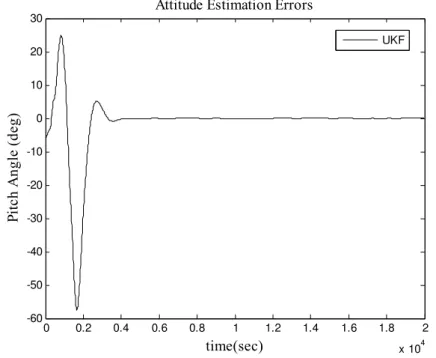
4.1 Pitch angle estimation error of the UKF used for attitude, gyro
and magnetometer bias estimation. 39
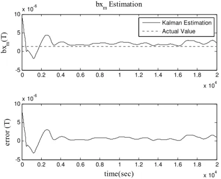
4.2 Estimation of the bias for the gyro aligned in the x axis by the
UKF used for attitude, gyro and magnetometer bias estimation. 40 4.3 Estimation of the bias for the magnetometer aligned in the x axis
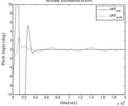
by the UKF used for attitude, gyro and magnetometer bias estimation. 40 4.4 Pitch angle estimation error of the UKFs with and without
magnetometer bias estimation when magnetometer bias exists in the measurements: UKFwb is the filter that estimates the magnetometer
biases and UKFwob is the filter that disregards them. 41 4.5 Estimation of the bias for the gyro aligned in the y axis by the
UKF without magnetometer bias estimation when magnetometer
bias exists in the measurements. 42
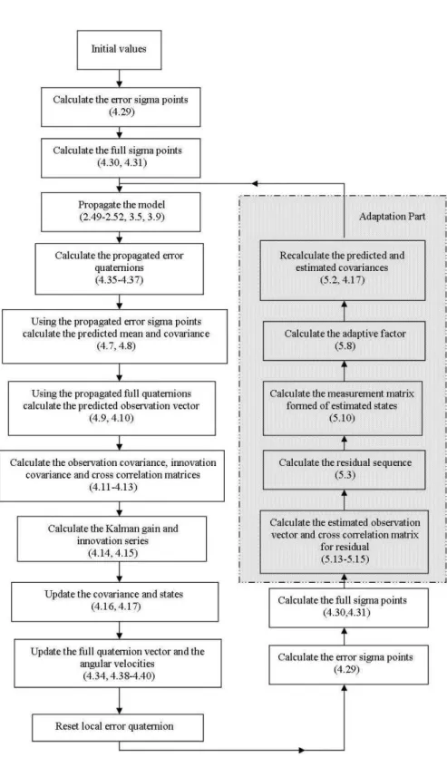
5.1 The overall estimation scheme for the AUKF with process noise
covariance scaling. 48
5.2 Norm of the attitude estimation errors for the conventional UKF (dashed line) and the AUKF with covariance scaling (solid line)
in case of attitude, gyro bias and magnetometer bias estimation. 49 5.3 Norm of the attitude estimation errors for the UKFa and AUKF
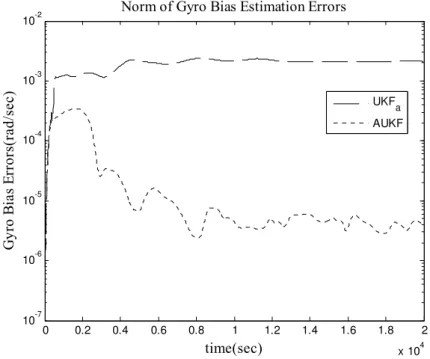
in case where attitude and gyro biases are estimated. 55 5.4 Norm of the gyro bias estimation errors for the UKFa and AUKF
in case where attitude and gyro biases are estimated. 56
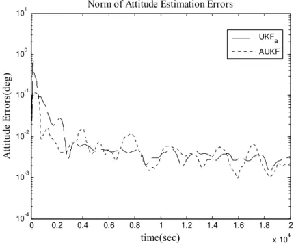
5.5 Norm of the attitude estimation errors for the UKFa and AUKF in
case where attitude, gyro biases and magnetometer biases are estimated. 57 5.6 Norm of the gyro bias estimation errors for the UKFa and AUKF
in case where attitude, gyro biases and magnetometer biases
are estimated. 57
5.7 Norm of the magnetometer bias estimation errors for the UKFa and AUKF in case where attitude, gyro biases and magnetometer
biases are estimated. 58
5.8 Norm of the magnetometer bias estimation errors for the UKFa and AUKF in case where attitude, gyro biases and magnetometer
biases are estimated (zero initial error for magnetometer biases). 59 5.9 Pitch angle estimation error for attitude, gyro and magnetometer
bias estimation scenario. Results for the UKF tuned by trial and error method are given with dotted line and the results for the
AUKF are given with solid line. 60
5.10 Estimation of the bias for the magnetometer aligned in the x axis for attitude, gyro and magnetometer bias estimation scenario. Results for the UKF tuned by trial and error method are given
with black line and the results for the AUKF are given with red line. 61 5.11 Pitch angle estimation error for the UKF and RUKF in case of
continuous bias. 67
5.12 Variation of the single scale factor for the RUKF in case of
continuous bias. 68
5.13 Pitch angle estimation error for the UKF and RUKF in case
of measurement noise increment. 69
5.14 Variation of the single scale factor for the RUKF in case of
measurement noise increment. 70
5.15 Pitch angle estimation error for the UKF and RUKF in case
of zero output failure. 71
5.16 Variation of the single scale factor for the RUKF in case
of zero output failure. 72
6.1 Estimation of the RMM in x axis. 76 6.2 Estimation of the RMM in x axis in case of sudden
change for two different process noise levels. 77 6.3 Estimation of the angular rate about x axis by the UKF
with low process noise in case of sudden change. 77 6.4 Variation of the GMA in case of change in the estimated
RMM terms (change at 2000th second). 80
6.5 The RMM estimation scheme in case of sudden change. 82 6.6 Estimation of the RMM in x axis in case of sudden change:
The UKF without change detection and adaptation is referred as “w/o adaptation”; the UKF, which is reinitialized after each change detection, is named as “reint”; and the proposed
estimation algorithm is shown as “adaptive”. 85
6.7 Estimation of the RMM in y axis in case of sudden change: The UKF without change detection and adaptation is referred as “w/o adaptation”; the UKF, which is reinitialized after each change detection, is named as “reint”; and the proposed
estimation algorithm is shown as “adaptive”. 86
6.8 Estimation of the RMM in z axis in case of sudden change: The UKF without change detection and adaptation is referred as “w/o adaptation”; the UKF, which is reinitialized after each change detection, is named as “reint”; and the proposed
estimation algorithm is shown as “adaptive”. 87
6.9 Variation of the GMA in case of change in the estimated RMM terms: The GMA for the regular UKF and UKF with
the proposed change detection and adaptation procedure. 88
7.1 The proposed RAUKF. 90
7.2 Integration of the RAUKF with the RMM estimator:
The overall attitude estimation scheme. 92
7.3 Estimation of the pitch angle via the RAUKF (red line) and
UKF (black line) as a part of the overall estimation scheme. 95
7.4 Estimation of the RMM term in z axis via the RAUKF (red line)
and UKF (black line) as a part of the overall estimation scheme. 96 7.5 Estimation of the roll angle via the AUKF (red line) and
AUKF (black line) as a part of the overall estimation scheme
in case of measurement malfunction. 97
7.6 Estimation of the RMM term in y axis via the RAUKF (red line) and UKF (black line) as a part of the overall estimation scheme
in case of measurement malfunction. 98
7.7 Estimation of the RMM term in y axis via the UKF with P adaptation (red line) and UKF without P adaptation (black line) as a part of the overall estimation scheme in case of instantaneous change in the estimated RMM parameters (figure is zoomed to
the estimations in between 30000th and 35000th seconds). 99 A.1 Limitations of the magnetic attitude control. 110
List of Tables
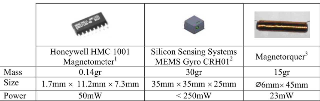
Page1.1 Typical magnetometer, MEMS gyro and magnetorquer examples
for nanosatellite applications. 3
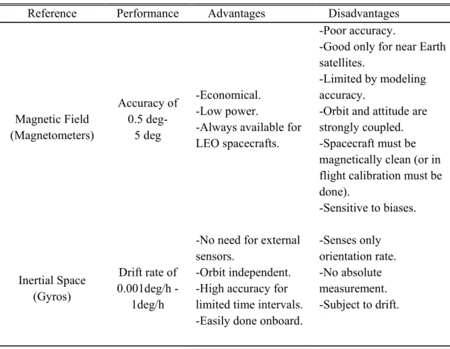
3.1 Characteristics of the attitude estimation reference sources. 25 5.1 Absolute estimation errors in case of continuous bias:
Regular UKF, RUKF with single scale factor (SSF) and
RUKF with multiple scale factor (MSF). 68
5.2 Absolute estimation errors in case of measurement
noise increment: Regular UKF, RUKF with single scale factor
(SSF) and RUKF with multiple scale factor (MSF). 70 5.3 Absolute estimation errors in case of zero output failure:
Regular UKF, RUKF with single scale factor (SSF) and
RUKF with multiple scale factor (MSF). 72
6.1 Absolute values of error for the RMM estimation
in case of sudden change. 78
6.2 Alarm time and the adaptation values for the proposed
UKF adaptation algorithm. 87
7.1 Comparison of the computational load of proposed algorithms with the EKF. (*) Here EKF is built as the Multiplicative Extended Kalman Filter which uses quaternions
for the attitude representation. 100
1. Introduction
1.1. Background and Motivation
Since the world’s first Earth orbiting artificial satellite, Sputnik I, was launched on 4 October 1957, mankind has always been working to reach the better in space missions. Progress in the miniaturization and the increase in the capability of the electronic devices are leading us towards a new era where performing complex space missions with small satellites will be possible.
The nanosatellite term refers to the satellites with mass less than 10kg (Fig. 1.1). The main motivation behind the nanosatellite missions is the significant cost decrease which is the direct result of reduced mass and complexity. Enabling COTS (commercial of the shell) technology in space and short system development periods are other advantages of nanosatellites. Since the investment cost is not high the developer may take the risk of using self-developed hardware or software for the mission and the satellite can be developed from scratch in a considerably shorter time than bigger satellites. Moreover the nanosatellite missions are generally single-aimed, so the satellite is not complex and the mission failure risk is lower than usual (Rendleman 2009).
Figure 1.1: GeneSat-1 of NASA: A nanosatellite mission example (Image Credit: NASA/Ames).
Although there are numerous researches on nanosatellites and this number is increasing day by day, the investigations are still far from being concluded. In this sense maybe the most important topic for researchers to deepen their investigations is the attitude determination and control of these satellites. According to (Bouwmeester and Guo 2010) despite the advanced technology for other subsystems, the attitude determination and control system (ADCS) and the subsystems that rely on the ADCS accuracy are underdeveloped for nanosatellites. It is added that the bottleneck for nanosatellites remains the attitude control performance especially in terms of dynamic control and control accuracies. The main reason underlying this problem is the mass, size and power restrictions. Unlike the big satellites high accuracy high-tech attitude sensors and actuators such as star-trackers and reaction wheels cannot be easily used for nanosatellite missions since they are heavy, big and do consume high power. The attitude must be determined and controlled precisely by using coarse sensors and actuators which are smaller and lighter (Soken et al. 2010). In this context the possible candidate for attitude sensing is economic, light and small magnetometers (Table 1.1) whereas the control might be performed by magnetic torque rods (magnetorquers). The primary problem is how to get high ADCS performance by using only magnetometers and magnetorquers.
The typical attitude determination accuracy for sole magnetometer based methods is 1-2deg (Bak 1999). The dominating error sources are the magnetic field uncertainty and bias in the measurements which is caused by several reasons such as magnetic charging during the launch and electrical charge on the other subsystems. Sun sensors are usually used for aiding the magnetometer measurements but in this case the attitude determination accuracy significantly degrades during the eclipse when the sun sensors are not usable. In this sense another candidate for using together with magnetometers is the gyros since they are also light and small instruments, especially after the recent developments ended up with MEMS (Microelectromechanical systems) gyros (Table 1.1). Magnetometer is preferred as the attitude sensor for almost 30% of all nanosatellite missions by 2010 while this number is around 12% for gyros (Bouwmeester and Guo 2010).
As for the attitude control, the magnetic control is the most popular method for the nanosatellites either as passive control with magnets or active control with magnetorquers. The magnetorquers are lightweight and energy-efficient (Table 1.1). Besides they do not have any mechanical part so they are more reliable compared to the reaction wheels and control moment gyroscopes. However the control accuracy is limited for these actuators because of the inherent complexity of the problem and pointing accuracy higher than 1deg. ( 1deg ) is not possible using only magnetic actuators in practice. The spacecraft should be magnetically clean also for satisfying high pointing precision with the magnetorquers.
Table 1.1: Typical magnetometer, MEMS gyro and magnetorquer examples for nanosatellite applications.
Honeywell HMC 1001 Magnetometer1
Silicon Sensing Systems
MEMS Gyro CRH012 Magnetorquer3
Mass 0.14gr 30gr 15gr
Size 1.7mm 11.2mm 7.3mm 35mm 35mm 25mm
⌀
6mm 45mmPower 50mW < 250mW 23mW
The main motivation of this study is to provide an accurate attitude determination method for the case that nanosatellite has magnetometers and gyros as the attitude sensors, and magnetorquers as the actuators. The aimed attitude determination and control accuracies are 0.1 and 1 deg, respectively. This is challenging because the attitude determination accuracy that can be satisfied by the regular algorithms for a nanosatellite carrying magnetometers and gyros is usually around 1deg (Vinther et al. 2011). Moreover although the angular rates can be controlled accurately by pure magnetic control approach the accuracy for the attitude itself cannot be reduced below few degrees and usually the yaw angle estimation is worse than the others (Wisniewski 2012). Mainly there are two reasons for such poor ADCS accuracy when the magnetometer, gyros and magnetorquers are used:
- Inherent complexity of the problem: Magnetometers are not accurate sensors due to the factors such as the disturbance fields caused by the spacecraft electronics, modeling errors in the Earth’s geomagnetic field and the external disturbances like ionospheric currents. For increasing attitude determination performance an accurate in-flight calibration of the magnetometers is necessary (Bak 1999). Moreover attitude control by using only magnetorquers is significantly challenging since at any instant the satellite is controllable in two-axes that are perpendicular to the magnetic field vector (Wisniewski 1996). For three axis controllability the spacecraft must experience the variation of the magnetic field along the orbit.
1 Source: Datasheet for Honeywell HMC1001/1002 and HMC1021/1022;
http://www.alldatasheet.com/datasheet-pdf/pdf/167569/HONEYWELL/HMC1021.html.
2 Source: Website of Silicon Sensing Systems Japan; http://www.sssj.co.jp/en/products/gyro/crh01.html.
3 Source: Candini et al. 2012.
- The size of the spacecraft: Because of the spacecraft’s compactness, the interaction between the subsystems is higher than the larger spacecrafts and that affects the magnetic cleanliness of the satellite which is a necessity for accurate attitude estimation and control with magnetic sensors and actuators. Besides the attitude hardware is more vulnerable against external disturbances because of the same reason. As for the control accuracy any disturbance source will make achieving higher accuracy more challenging so a magnetically clean satellite is a preliminary necessity.
Therefore for an accurate ADCS by using magnetometers, gyros and magnetorquers these issues should be analyzed carefully and appropriate solution techniques should be given. This thesis contributes to the literature within this context. Different than the existing studies we address the problems such as in-orbit estimation of magnetometer biases and residual magnetic moment and try to increase the system accuracy by using more powerful estimation algorithms, which are proposed by the authors. First of all each problem is addressed individually and possible solution methods, which are mostly based on the adaptation of the attitude estimator algorithms, are given. Then these solution techniques are integrated in order to propose an overall attitude determination scheme for the satellite. The theory is supported by the demonstrations and performance analysis for the proposed attitude determination method. Details for the contribution are given in Section 1.3 after reviewing the current literature in Section 1.2.
1.2. Literature Survey
The attitude determination and control for nanosatellites is a widely discussed topic in the literature. In general scope, the solutions that have been proposed in order to increase the ADCS system efficiency might be considered in two categories. The first category includes the design solutions that cover the selection of the appropriate sensors, forming the layout of the subsystems in an optimal way (Han et al. 2012) and designing a completely new sensor or actuator (Candini et al. 2012). On the other hand, the algorithmic solutions which investigate the possible algorithm based techniques to solve a specific problem (Reijneveld and Choukroun 2012; Pong et al. 2012; Vinther et al. 2011) fall in the second category. The solutions in the latter category mainly aim at proposing a new method for nanosatellite implementations such that the system performance can be increased even using the existing hardware and usually they focus on a specific problem such as onboard sensor calibration, robustness of the ADCS algorithm against the external/internal disturbances etc. The studies presented in this thesis may be regarded as a part of this second category.
In this thesis the main aim is to increase the ADCS performance of a nanosatellite that carries magnetometer, gyros and magnetorquers onboard as the attitude hardware. As aforementioned this aim is accomplished by solving several interconnected practical problems.
In a broad perspective the attitude determination problems are related to magnetic disturbance compensation which is needed in order to guarantee the magnetic cleanness of the spacecraft. Our first problem is finding an accurate estimation algorithm for the in-orbit and real time estimation of the magnetometer biases and that is an obligation as aforementioned. This is a recent topic for nanosatellite applications and since the magnetometers are popular sensors for this type of satellites there are many documented studies especially on magnetometer calibration. In (Inamori et al. 2009) the magnetometer biases are estimated as a part of the magnetic disturbance compensation for a nanosatellite. The Unscented Kalman Filter (UKF) is used as the estimator algorithm. Han et al. (2012) proposes both pre-launch on ground and post-launch in-orbit magnetometer calibration schemes for Chinese ZDPS-1A nanosatellite. In (Soken and Hajiyev 2012) along with the magnetometer biases the scale factors are also considered and a UKF based reconfigurable attitude estimation and magnetometer calibration method is presented. Lastly Vinther et al. (2011) investigates the effects of magnetometer and gyro calibration on the attitude accuracy and gives a simultaneous estimation algorithm using the full-order UKF.
The biggest difficulty that arises in case of in-orbit real time sensor bias estimation is tuning the estimator. This provides a basis for the second problem which is the determination of the process noise covariance for the UKF when the sensor biases or scale factors are included in the state vector. For the case where the UKF is used for estimating only the attitude and gyro biases as a reduced-order filter the process noise covariance matrix can be approximated analytically (Crassidis and Markley 2003) likewise the general case (Farrenkopf 1978; Fosbury 2011). But this method fails if the magnetometer biases are also estimated as a part of the state vector. One possible solution technique is to use an adaptive algorithm to tune the UKF as discussed in this thesis. The adaptation of the UKF is also a necessity for building a filter which is robust against any kind of sensor malfunctions. Since the spacecraft is vulnerable against external disturbances there is a high risk for the magnetometer measurements to be affected and give faulty outputs for a period of time. Unless the filter is built robust against that kind of malfunctions, they will deteriorate the estimation performance significantly. That will be the third problem examined in this study.
In literature there are several methods to adapt the linear Kalman filter (KF). Unquestionably, the pioneering methods in this area have been proposed by Mehra (Mehra
1970; Mehra 1972). Specifically the covariance matching technique discussed in (Mehra 1972) may be considered as the fundamental of the algorithms proposed in this thesis. The main drawback of these studies, and as well their successors that examine the adaptation of the KF (Geng and Wang 2008; Kim et al. 2006; Odelson et al. 2006; Dunik et al. 2009), they are generally appropriate for discrete-time linear systems and cannot be used as a method for the adaptation of the UKF without any correction or modification.
In this sense, researches on the Adaptive Unscented Kalman Filter (AUKF), which can be used for nonlinear systems, should be examined. In (Han et al. 2009), two distinct methods are described as the AUKF algorithms. In the first method, the MIT rule is used to derive the adaptive law and a cost function is defined in order to minimize the difference between the filter computed covariance and the actual innovation covariance. The algorithm is used for the Q-adaptation (process noise covariance adaptation), which is required for tuning the filter against uncertainties. It is stated that a similar approach may be pursued for the R- adaptation (measurement noise covariance adaptation), which is necessary for building a filter robust against sensor malfunctions. As a deficiency, the presented algorithm requires calculation of the partial derivatives and that introduces a relatively large computational burden as it is also stated by the authors themselves. In the second method, two UKFs are run in parallel as master and slave filters. Its computational demand is lower than the first method but as it is known (Vinther et al. 2011), despite being free of the Jacobian calculations, the computational burden of the UKF is not very low because of the sigma point calculations. Therefore, using two UKF algorithms in a parallel manner still increases the required computation burden significantly. Hence the main problem for both of the methods presented in (Han et al. 2009) is high computational load. Nonetheless in (Liu and Lu 2009; Shi et al. 2009) Saga-Husa noise statistics estimator is integrated with the UKF in order to build an AUKF. Although it may give satisfactory results for the target tracking problem, this method has an unstability issue; when the noise covariance loses its semi- positive definiteness, the filter diverges.
In (Cao and Tian 2009) an adaptive UKF algorithm is proposed to improve the estimation of error covariance matrices. By introducing measurement innovation into the estimation of error covariance matrices, the proposed algorithm can compute the Kalman gain adaptively and make the innovation series of the future measurement uncorrelated. However, the presented AUKF algorithm is valid, if only the model of dynamics is nonlinear, but the model of measurements is linear. In (Song and He 2009) a slave UKF is proposed to estimate the covariance of system noise online. An AUKF is developed and applied to nonlinear joint estimation of both time-varying states and modeling errors for helicopter. The filter is composed of parallel master and slave UKFs. While the master UKF estimates the states or parameters, the slave filter estimates the diagonal elements of the noise
covariance matrix for the master UKF. Such a mechanism improves the adaptive ability of the UKF and enlarges its application scope but as the second method given in (Han et al. 2009) it is complex and requires high computational load.
The UKF may be also built adaptively by using fuzzy logic based techniques. In (Jwo and Tseng 2009) Fuzzy Logic Adaptive System (FLAS) aids the interacting multiple models and by switching between filters suitable value for the process noise covariance can be determined. As a disadvantage such method also requires more than one filter running simultaneously. In (Jwo and Chung 2010) a sensor fusion method based on the combination of adaptive UKF and fuzzy logic adaptive system for the ultra-tightly coupled GPS/INS integrated navigation is presented. Through the use of fuzzy logic, the FLAS has been incorporated into the AUKF as a mechanism for timely detecting the dynamical changes and implementing the on-line tuning of the factors in the weighted covariance matrices by monitoring the innovation information so as to maintain good estimation accuracy and tracking capability. Although it is possible to get satisfactory results for some specific cases, the essences of these kinds of fuzzy methods are human experience and heuristic information; in out of experience cases they may not work.
Another practical problem, which should be solved by the UKF adaptation, is the Residual Magnetic Moment (RMM) estimation for nanosatellites and this is the fourth issue discussed in this thesis.
Generally, the RMM is the main attitude disturbance source for the low earth orbit (LEO) nanosatellites (Sakai et al. 2006b). Other disturbances such as the gravity gradient, sun pressure, aerodynamic drag have relatively less effect because of the small size of the satellite and can be minimized during the design process (Inamori et al. 2009). However, the magnetic disturbance is mainly caused by the onboard electric current loop, small permanent magnet in some devices or some special material on the satellite, and does not strongly depend on the satellite size (Sakai et al. 2008). Hence, the RMM must be compensated in-orbit with an active control strategy.
The effects of the RMM on the attitude determination and control accuracy for small satellites and the necessity for its compensation are well discussed in (Sakai et al. 2008; Inamori et al. 2009; Steyn and Hashida 2001; Suehiro 2010; Hosonuma et al. 2012). The orthodox way to cancel out the disturbance caused by the RMM is to use a feedback controller but the efficiency of the method depends on several conditions such as the sensor noise, computational performance or plant model accuracy (Sakai et al. 2008). Another method is to use a feedforward cancellation technique and when this technique is used the performance depends on the accuracy of the RMM estimation.
In (Sakai et al. 2006b; Sakai et al. 2008), an observer is proposed to estimate the RMM whereas in (Steyn and Hashida 2001; Hosonuma et al. 2012) the RMM is estimated using the Extended Kalman Filter (EKF). In (Inamori et al. 2009), as well as the EKF, an UKF is designed for the RMM estimation and the estimation accuracies of these two different KFs are compared. In these studies, the RMM components are considered to be constant in time. However, in practice, these parameters may change with sudden shifts because of the instantaneous variations in the onboard electrical current. Such instantaneous variations in the current may be caused by switching on/off of the onboard electronic devices or going into/out of eclipse. In such cases, the KF cannot catch the new value of the parameter quickly if it is designed with a small process noise covariance in order to increase steady state estimation accuracy. The main issue is, especially if we use the feedforward cancellation technique for the RMM compensation, then, as discussed, the estimation accuracy is essential and so the KF must be designed with small process noise covariance. In other words, the inherent tracking capacity of the KF that can be provided by choosing a high process noise covariance must be sacrificed in order to increase the overall system performance. Therefore, if we want to design a KF with good tracking capability, as well as the high steady state accuracy, then the filter should be adaptively designed such that it gives both good estimation results when there is no change in the parameter and good tracking performance when the parameter is changed.
Change detection and the KF adaptation in case of abrupt changes in the estimated parameters is a common issue in many fields from automotive to computer systems (Gustafsson 2000; Hartikainen and Ekelin 2006) and there are several documented methods investigating this topic. In general, these methods may be categorized in two: the methods that use one KF and detect the change by applying a whiteness test on the innovation vector of the filter and methods that use a bank of filters with different statistical information for changes with different characteristics (such as shifts with different magnitudes) (Gustafsson 2000). An example for the latter method is the use of two different KFs where one of them is designed with low process noise covariance for steady state accuracy and the other one is with a high process noise covariance for agility in case of change. In general the multiple model based approach with several KFs running parallel gives better results compared to the single filter based adaptive recursive estimation algorithms. However in return for the increasing accuracy, the algorithm becomes more complex and so the computational load increases as well. Besides, as a prerequisite for designing the filters the characteristics of the changes (e.g. the magnitude of different shifts) must be known (Hartikainen and Ekelin 2006).
A simple technique for change detection is to apply a whiteness test on the innovation vector of the KF in order to check whether a change in the system occurred. A well known
test is the Cumulative Sum (CUSUM) test in which the filter innovations are transformed into distance measures with different characteristics corresponding to the desired design properties and the test built upon these distance measures (Gustafsson 2000; Page 1954; Basseville and Nikiforov 1993). The next step after the change detection is to perform a correction (or adaptation) on the filter statistics in order to adapt the filter to the changing conditions and get better tracking capability. The easiest and most straightforward method is to restart the filter (Gustafsson 1996) after each change detection which basically increases the estimation covariance to get better tracking. Another way of adaptation is to increase the estimation covariance of the related state for one time step or a period of time by multiplying with a factor (Stenlund and Gustafsson 2002). Nonetheless, it is also possible to perform similar adaptation by multiplying the process noise covariance matrix with the scale factor instead of the estimation covariance of the KF (Gustafsson 2000; Gustafsson 1996). The main disadvantage of all these adaptation techniques is being heuristic; the adaptation is based on the designer’s experiences. As in the first adaptation method, if the filter is restarted after each change detection then the magnitude of the change does not have any significance on the performed adaptation and after some certain changes the KF may give a bad transient behavior (Gustafsson 1996). On the other hand, when the estimation covariance or the process noise covariance matrix is multiplied with a scale factor after the change is detected, the scale factor must be selected carefully such that it represents the required response of the filter for all possible changes. However, as it is extensively discussed in (Hartikainen and Ekelin 2006) such selection is not possible and the KF response is very sensitive to the value of the scale factor. Besides, if the scale factor is applied for a period instead of just one time step (periodic correction instead of momentarily correction) then determination of the adaptation period appears as another problem. Therefore, the main drawback of the existing single KF based change detection and adaptation algorithms is the necessity to know the characteristics of the change (e.g. the magnitude of the shift) a priorily in order to obtain a precise scale factor for correction and achieve successful adaptation as a result; none of them may perform well under circumstances other than they are designed for.
1.3. Contribution of the Thesis
In general this thesis proposes a simple yet accurate attitude determination method for increasing the ADCS performance of nanosatellites with magnetic sensors and actuators. In order to achieve that first we increase the accuracy of the magnetometer outputs by proposing an appropriate in-orbit calibration algorithm. The tuning problem for the filter that is used for calibration as well as the attitude estimation is overrun by the adaptive Kalman filtering approach. The same filter is made robust against faults in the
measurements. That is a necessity in the severe space environment especially for nanosatellites which are highly vulnerable against the internal and external disturbances. As the next step, the RMM is estimated to cancel out the effects of the magnetic disturbance and assure the magnetic cleanliness of the satellite for the attitude control purpose. The instantaneous changes in the RMM are regarded and the estimator UKF is adapted as it gives accurate estimations at any case. In the final section, which may be regarded as the core of this study, the given UKF adaptation techniques are integrated and an overall attitude determination scheme is introduced. The scheme is demonstrated for the attitude determination of the nanosatellite and its performance is analyzed by comparisons with the existing algorithms. Moreover, in the appendix a brief discussion about possible novel methodologies for pure magnetic attitude controller, which can work independently from the orbital periodicity of the geomagnetic field, is given.
The main contributions of this thesis can be listed as:
In Section 4.3 a magnetometer and gyro bias estimation algorithm is presented. The UKF, a rather novel Kalman filter, which does not have so many implementation examples for the bias estimation in literature, is used as a part of the estimation system. Differently from the existing studies both magnetometer and gyro biases are estimated simultaneously as well as the attitude parameters by using a gyro-based model. The results were presented in (Soken and Sakai 2011).
A novel adaptive scaling method for the process noise covariance of the UKF is given in Section 5.1.1. The adaptation is performed using a single adaptive factor calculated in the base of the residual sequence and the process noise covariance matrix tuned dynamically via multiplication with this factor. It is demonstrated that the given AUKF algorithm provides more accurate attitude estimation results than the regular UKF. The results were presented in (Soken and Sakai 2012a).
In Section 5.1.2 an adaptive method for tuning the process noise covariance matrix of the UKF is proposed for the general case. This filter algorithm is also called as the AUKF. The method is based on Maybecks’s maximum likelihood estimator (Maybeck 1982), which has been already investigated for several different problems. Firstly it is shown that the adaptation method can be generalized for the nonlinear systems so it holds true for a nonlinear problem where the UKF is used as the attitude estimator. Then the method is tested in various scenarios for the attitude and sensor bias estimation and the results are compared with the filter where analytically approximated process noise covariance matrix (Farrenkopf 1978) is used. The
results were presented in (Soken and Sakai 2012b) and published in (Soken and Sakai 2012c).
A Robust Unscented Kalman Filter (RUKF) algorithm is proposed for the case of magnetometer faults in Section 5.2. With simulations it is demonstrated that the regular UKF fails about giving accurate attitude estimation results if the magnetometer output is faulty whereas the RUKF ensures estimation accuracy for any case. The applied adaptation scheme is similar to the one given in (Soken and Hajiyev 2010). However, in this study the attitude estimation problem is generalized and instead of the Euler angles the quaternions are used as the attitude representation method. Besides, the robust Kalman filters are examined for different measurement system failure cases. The results for the adaptation using single scale factor were published as a part of (Soken et al. 2013a).
In Section 5.2.2 the UKF is built robust against measurement malfunctions using multiple scale factors. The key findings for the adaptation with multiple scale factors were presented in (Soken et al. 2012a) and published in (Soken et al 2012b). Comparison of the single and multiple scale factor based adaptation schemes was given in (Soken et al. 2013a).
An in-orbit RMM estimation method for small satellite applications is discussed in Chapter 6. Unlike the existing studies in the literature, the unexpected abrupt changes in the RMM are also considered. The adaptation method that tunes the covariance of the UKF regarding the magnitude of the change is a novel approach. The specific results for the UKF were presented in (Soken and Sakai 2013). The version generalized for all KF applications was published in (Soken et al. 2013b).
In Chapter 7, the proposed UKF algorithms are integrated to build an overall attitude estimation scheme for the nanosatellite. The given integration method and so the overall scheme is tested via demonstrations and its performance is comprehensively analyzed by comparisons with the exiting methods. The proposed scheme is a new one that can be used for estimating all the necessary parameters for attitude determination and control of a nanosatellite with magnetic sensors and actuators.
1.4. Thesis Overview
The thesis aims at proposing an attitude determination method for increasing the ADCS performance of nanosatellites with magnetic sensors and actuators. The first two chapters constitute the preliminary basis for the next chapters by introducing the motion model for the satellite and the models for the attitude sensors. The rest of the study may be divided into two: the first part which examines several practical problems for the attitude determination and control of the nanosatellite and the second part which presents the overall attitude determination algorithm. The details are given below chapter by chapter:
Chapter 2: Satellite Mathematical Model
This chapter first gives the definition of the coordinate systems used throughout the thesis. After a brief description for the quaternions for attitude parameterization, the mathematical model for the satellite’s motion is presented.
Chapter 3: Sensor Model
This chapter presents the models of the sensors that are used for getting attitude information. The Earth magnetic field model is presented as a part of the discussions for the magnetometer model. The magnetometer and gyro models are given for the common case that we regard the sensor biases.
Chapter 4: Sensor Bias Estimation
In this chapter an UKF based magnetometer and gyro bias estimation algorithm is presented as a part of the attitude determination procedure for a nanosatellite, which has three magnetometers and three gyros as measurement sensors. Differently from the existing studies both the magnetometer and gyro biases are estimated as well as the attitude parameters. As a basis for building the bias estimation algorithm, first the UKF and its implementation method for attitude estimation are given. A comparison for the dynamics-based and gyro-based estimation models is also included. The effects of magnetometer bias estimation on the attitude determination accuracy are discussed.
Chapter 5: Adaptation Methods for the UKF
This chapter presents the adaptation methods for a UKF used for nanosatellite attitude estimation. Mainly two different problems met in practice are examined. In the first part, an adaptive method for tuning the process noise covariance matrix of the UKF is given and the AUKF algorithm is tested in various scenarios for the
attitude and sensor bias estimation. Both scaling and estimation techniques for the process noise covariance adaptation are discussed. In the second part, a Robust Kalman Filtering method against the measurement faults is proposed. The adaptation is performed following both single and multiple scale factor based schemes and the results are applied for the UKF in order to build a RUKF. The RUKF is tested for the attitude estimation of the nanosatellite and the results are compared with the regular UKF for various measurement faults.
Chapter 6: The Residual Magnetic Moment Estimation
In this chapter a method for in-orbit estimation of time-varying RMM is presented. First the deteriorating effects of the sudden RMM changes on the estimation accuracy are examined. Then a new method for change detection and Kalman Filter adaptation is presented. By using this simple approach, the covariance of the Kalman filter is adapted to get better tracking in case of unexpected abrupt changes in the RMM without sacrificing the estimation accuracy. The results are applied for the nanosatellite attitude estimation problem.
Chapter 7: Demonstration of the Proposed Attitude Determination Scheme In this chapter, first a possible integration scheme for the estimation algorithms, which were discussed in the previous chapters, is proposed. As a consequence, an overall attitude determination algorithm for a nanosatellite carrying magnetometers, gyros and magnetorquers as the attitude hardware is given. Then this scheme is tested by demonstrations for the ADCS of the nanosatellite. The results are evaluated regarding the main aim of the thesis and analyzed via comparisons with the existing methods.
Chapter 8: Conclusion and Recommendations
In this chapter the concluding remarks and recommendations for the future work are given.
2. Satellite Mathematical Model
2.1. Coordinate Systems
The coordinate systems used in this thesis are the satellite body frame, which matches with the principal axes of inertia of the satellite, orbit reference frame and inertial reference frame which is Earth centered. The definitions of these coordinate systems are given below. Earth Centered Inertial Frame: The origin of the frame is located at the centre of the Earth. The z axis shows the geographic North Pole while the x axis is directed toward the Vernal Equinox ( - the point where the Sun crosses the celestial Equator in March on its way from south to north). The y axis completes the coordinate system as the cross product of z and x axes (Fig. 2.1a).
Orbit Reference Frame: The origin of the frame is at the mass centre of the spacecraft. The z axis is in nadir direction (towards the centre of the Earth) and the y axis is tangential to the orbit (aligns with velocity vector of the spacecraft in case of circular orbit). The x axis completes to the orthogonal right hand system (Fig. 2.1b).
Satellite Body Frame: The origin of the frame is located at the centre of mass of the satellite. The axes are directed towards the principal inertial axes of the spacecraft. Three parameters named as Euler angles set the condition of the body frame related to the orbital coordinate system. When the direction cosine matrix is identity matrix the satellite body frame matches with the orbital frame (Fig. 2.1c).
Figure 2.1: Coordinate systems.
2.2. Quaternions for Attitude Representation
The quaternion attitude representation is a technique based on the idea that a transformation from one coordinate frame to another may be performed by a single rotation about a vector e defined with respect to the reference frame. The quaternion, denoted here by the symbol q , is a four element vector, the elements of which are functions of the vector e and magnitude of the rotation, Φ :
1 1sin
q e 2 (2.1) 2 2sinΦ
q e 2 (2.2) 3 3sinΦ
q e 2 (2.3)
4 cosΦ
q 2 (2.4) Here e e e are the components of the vector 1, , 2 3 e. The vector which shall be transformed is rotated around e with an angle of Φ . As a result, by the use of quaternions a transfer from reference frame to body frame can be denoted by a single rotation around a vector defined in the reference frame.
A quaternion with components q1, q2 , q3 and q4 may also be expressed as a four parameter complex number with a real component q and three imaginary components, 4 q , 1
q and 2 q as follows: 3
qq4iq1 jq2kq3 , (2.5) where , , i j k are hyper-imaginary numbers with the characteristics of;
i2 j2 k2 (2.6) 1 ij (2.7) ji k jk (2.8) kj i ki (2.9) ik j Also, the redundancy of the quaternions must be noted as;
q12q22q32q42 (2.10) 1 2.2.1. Vector Transformation by Quaternions
A vector quantity defined in the body axes, r may be expressed in the reference axes as B r R using the quaternions directly. First define a quaternion, r , in which the complex Bq components are set equal to the components ofr , and with a zero scalar component, that B is, if:
B ix jykz
r (2.11)
q 0
B ix jykz
r (2.12) This is expressed in the reference axes as r using: Rq
*
q q
R B
r q r q
(2.13) where q*
q4iq1 jq2kq3
is the complex conjugate of q .Hence,
q
r =R
q4iq1 jq2kq3
0 ix jykz
q4iq1 jq2kq3
42 12 22 32 1 2 4 3 1 3 4 2
0 q q q q x 2 q q q q y 2 q q q q z i
2 q q1 2 q q4 3 x q42 q12 q22 q32 y 2 q q2 3 q q z j4 1
2 q q1 3 q q4 2 x 2 q q2 3 q q y4 1 q42 q12 q22 q32 z k
(2.14)
Alternatively, r may be expressed in matrix form as follows: Rq
q q
R A B
r r , (2.15)
where 0 0
A 0
A
,
0
q
R B
r r and
2 2 2 2
1 2 3 4 1 2 3 4 1 3 2 4
2 2 2 2
1 2 3 4 1 2 3 4 2 3 1 4
2 2 2 2
1 3 2 4 2 3 1 4 1 2 3 4
2( ) 2( )
2( ) 2( ) .
2( ) 2( )
q q q q q q q q q q q q
A q q q q q q q q q q q q
q q q q q q q q q q q q
(2.16)
which is equivalent to writing:
R A B
r r . (2.17) Here A is the same direction cosine matrix that is used for transformation from body to reference frame.
2.2.2. Propagation of Quaternions by Time
While defining the kinematic equations of motion with quaternions, time dependence of them must be used and that can be derived from the product relation (Wertz 1988).
Multiplication of quaternion is performed in a way not too different from complex number multiplications. However the order of the process is important. By using the characteristic of hyper-imaginary numbers;
4 1 2 3
4 1 2 3
I I I
II I I
q iq jq kq q iq jq kq
q qq , (2.18)
1 1 2 2 3 3 4 4
( 1 4 2 3 3 2 4 1)I I I I
II I I I I
q q q q q q q q i q q q q q q q q
q
j(q q1 3I q q2 4I q q3 1I q q4 2I)k q q( 1 2I q q2 1I q q3 4I q q4 3I). (2.19)