お問合せ先
茨城大学学術企画部学術情報課(図書館) 情報支援係
http://www.lib.ibaraki.ac .jp/toiawas e/toiawas e.html
R O S E リポジトリいばらき (茨城大学学術情報リポジトリ)
T itle
A Note on the C oriolis F orce in the R otating F rame of
R eference
A uthor(s )
Y A J IMA , Y usuke
C itation
茨城大学教育学部紀要. 自然科学 = B ulletin of the F aculty
of E ducation, Ibaraki University. Natural science, 67: 1-5
Is s ue D ate
2018-01-30
UR L
http://hdl.handle.net/10109/13509
R ig hts
*Laboratory of Experimental Physics, College of Education, Ibaraki University, Mito 310-8512 Japan.
A Note on the Coriolis Force in the Rotating Frame of Reference
Yusuke Yajima*
(Accepted August 31, 2017)
Abstract
A simple method is presented to show how the moving body under force free condition changes
its direction when observed on the rotating frame. If only the qualitative and synoptic effect of the Coriolis force is of interest, the standard procedure of the coordinate transformation from the
inertial frame to the rotating frame and temporal differentiation is more than sufficient, and the method shown here sufices to reach an understanding more quickly.
Introduction
Newton’s second law of motion, i.e., the acceleration α of a body is equal the force applied F divided by the mass m ; α= F/m, holds only in the inertial frame of reference whose existence is the principal assertion of Newton’s irst law of motion often referred to as “the law of inertia.” In the non-inertial frames, this relation is no longer valid and some apparent forces have to be taken into account in order to correctly describe the acceleration observed on those frames. Among such apparent forces, the one associated with a
moving body appearing characteristically in the rotating frame is the Coriolis force (Goldstein et.al. 2000). The Coriolis force plays a signiicant role in large scale meteorological phenomena, since the coordinate system attached to any point on Earth, except for those on the equator, is rotating. The horizontal wind low, if driven solely by real pressure-gradient and frictional forces, would be directed along the pressure gradient. But the apparent Coriolis force delects the wind low from this direction, which can be readily observed by comparing the isobar chart (Fig. 1(a)) with the infrared satellite image of the cloud (Fig. 1(b)).
図
rt, and (b) cor http://www.tenki.j (a)
Fixed, inertia
y
x’ y’
ωt
x’ ’
ωt
図
llite image.
(a) (b)
olid line),
x y
x’ y’
ωt
(x, y) (x’, y’)
ωt
(a) (b)
2
The standard treatment of the Coriolis force problem proceeds with the coordinate transformation from
the fixed frame to the rotating frame followed by a sequence of temporal differentiation. By using a
differentiation rule for a set of functions,
A(t),B(t)
;
t
t
B
t
t
A
t
B
t
t
B
t
t
A
t
A
'
(
)
cos
sin
)
(
'
)
(
sin
)
(
'
cos
)
(
'
)
(
dt
d
/
㻌 㻌
t A dt dB t B dt dA dt dB t A dt dB t B dt dA dt dA cos ' ' sin ' ' sin ' ' cos ' '
, (1)
twice, position
x(t),y(t)
, velocity
dx/dt,dy/dt
, and acceleration
2 2 2 2
/ ,/dt d y dt
x
d
of a
particle in the inertial frame can be
expressed by their counterparts,
x'(t),y'(t)
,
dx'/dt,dy'/dt
,
and
2 2 2 2
/ ' , /
' dt d y dt
x
d
㻘
in the frame rotating uniformly around the inertial frame at a rate of
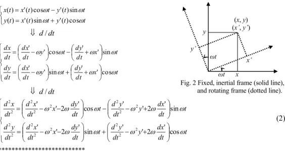
(Fig. 2)
㻚
The actual calculation can be carried out as below.*************************** t t y t t x t y t t y t t x t x '()cos sin ) ( ' ) ( sin ) ( ' cos ) ( ' ) (
dt
d
/
㻌
t x dt dy t y dt dx dt dy t x dt dy t y dt dx dt dx cos ' ' sin ' ' sin ' ' cos ' '
dt
d
/
t dt dx y dt y d t dt dy x dt x d dt y d t dt dx y dt y d t dt dy x dt x d dt x d
cos ' 2 ' ' sin ' 2 ' ' sin ' 2 ' ' cos ' 2 ' ' 2 2 2 2 2 2 2 2 2 2 2 2 2 2 2 2(2)
***************************Table 1. Position, velocity, and acceleration transformed from the fixed (left) into rotating (right) frames.
position velocity acceleration
x ⇔ x' vx dt dx ⇔ ' ' ' ' ' y v y dt dx x x dt x d 2 2 ⇔ ' 2 ' 2 2 2 ' 2 ' ' ' 2 ' ' y
x x v
dt dy x dt x d
y ⇔ y' vy
dt dy ⇔ ' ' ' ' ' x v x dt dy y y dt y d 2 ⇔ ' 2 ' 2 2 2 ' 2 ' ' ' 2 ' ' x
y y v
dt dx y dt y d
As summarized in Table 1., the acceleration observed in the rotating frame,
(
'
x',
'
y')
㻘 and that in thefixed frame,
(
x,
y)
, are related as(
'
,
'
)
(
'
2
'
,
'
2
'
')
2' 2 '
' y x y y x
x
x
v
y
v
. This means that the uniform linear horizontal motion of a force free body in which(
x,
y)
(
0
,
0
)
is seen as an accelerating motion when observed in the rotating frame;(
'
,
'
)
(
'
2
'
,
2'
2
'
')
' 2
'
' y y x
x
x
v
y
v
. The Fig. 2 Fixed, inertial frame (solid line),and rotating frame (dotted line).
x㻌
y
㻌
x’㻌 y’㻌
ωt㻌
(x, y)㻌 (x’, y’)㻌
ωt㻌
Bull. Coll. Educ., Ibaraki Univ.(Nat. Sci.)67(2018)
apparent force that induces the position dependent part,
(
2x
,'
2y
'
)
, is the centrifugal force, and thevelocity dependent part,
(
2
v
'
y',
2
v
'
x')
is interpreted by assuming the apparent Coriolis force. Theapparent acceleration caused by the Coriolis force,
a
C
(
2
v
'
y',
2
v
'
x',
0
)
, is perpendicular to thevelocity,
v
'
(
v
'
x',
v
'
y',
0
)
; aCv'0; it alters the direction of motion to the right if the rotation of theframe is counter-clockwise and to the left if the rotation is clockwise;
a
C
v
'
2
(
v
'
x2
v
'
y2)(
0
,
0
,
)
.This standard procedure is rigorous and complete; it gives the exact temporal behavior of the apparent
acceleration,
(
'
x'(
t
),
'
y'(
t
))
, observed on the rotating frame. However, in most applications of movingbody dynamics in the rotating frame such as those in meteorological problems stated earlier, the major or the
only concern is the sense of deflection caused by the Coriolis force, for which the above fully quantitative
procedure is more than sufficient. In this note, instead of going into the lengthy quantitative discussion just to
reap only the qualitative conclusions in much abundant results derived from it, a simpler and more intuitive
method to perceive the sense of the Coriolis force deflection is presented.
Method
Components of the apparent acceleration, 'x'(t) and
'
y'(
t
)
, are the continuous functions of time t,and, accordingly, contain information on an infinite number of temporal points. However, considering that
they are the second derivatives of the position,
'
x'
d
2x
'
/
dt
2 and
'
y'
d
2y
'
/
dt
2, and the secondderivative is derived in general by the limit operation on three points;
d
2f
/
dx
2
(
f
(
x
x
)
) ( 2f x
2
/
))
(
x
x
x
f
;(
0
x
)
, it is noticed that the direction of the Coriolis force deflection can be confirmed qualitatively by referring to positions of a moving body only at three temporal points.A straightforward and intuitive way to see the positions of a moving body at three consecutive temporal
points is to plot them on coordinates; it is undoubtedly far easier to plot only three points than to follow the
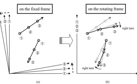
rigorous standard procedure stated above. In Fig. 3 (a), three consecutive positions of linearly moving bodies
are plotted with the corresponding frame rotating counter-clockwise. This is the fixed inertial frame view of
the motion. By overlapping rotating frames without altering the relative arrangement of the positions of
bodies and associated frames, the rotating frame view is obtained as Fig. 3 (b). It is evident that linearly
moving bodies show the apparent deflection to the right for the observer on the frame rotating
counter-clockwise. This is the way how the wind flows in the northern hemisphere reflected on the cloud
pattern in Fig. 1(b), since the frame of reference attached on any points of Earth’s surface in the northern
hemisphere is rotating counter-clockwise. Quite similarly, from the fixed frame view of the linearly moving
bodies (Fig. 4(a)), the rotating frame view can be constructed for the frame rotating clockwise (Fig. 4(b)). It
can be seen immediately that the clockwise rotation of the frame gives rise to the Coriolis force deflection to
the left. This is the situation observed for the wind flow in the southern hemisphere.
The above three-point-plot can thus give qualitative information on the direction of the deflection
observed in the rotating frame, sufficient for most practical Coriolis force problems, without recourse to the
4
Fig. 3 Positions of bodies (circles) moving linearly at three consecutive temporal points and the frame rotating counter-clockwise as observed (a) on the fixed frame, and (b) on the rotating frame.
on the fixed frame
on the rotating frame
(a)
①㻌
②㻌
③㻌
①㻌
②㻌
③㻌
①㻌
②㻌
③㻌
①㻌
②㻌
③㻌
(b)
①㻌
②㻌
③㻌
①㻌
②㻌
③㻌 right turn
right turn
①㻌
②㻌
③㻌
on the fixed frame
on the rotating frame
①㻌
②㻌
③㻌
①㻌
②㻌
③㻌
(a)
②㻌③㻌
①㻌
①㻌
②㻌
③㻌 (b)
①㻌
②㻌
③㻌
①㻌
②㻌
③㻌 left turn
left turn
①㻌
②㻌
③㻌
Fig. 4 Positions of bodies (circles) moving linearly at three consecutive temporal points and the frame rotating clockwise as observed (a) on the fixed frame, and (b) on the rotating frame.
Bull. Coll. Educ., Ibaraki Univ.(Nat. Sci.)67(2018)
5 Conclusion
The direction of the apparent deflection of a moving body by the Coriolis force observed in the rotating
frame of reference can be easily perceived by first (i) plotting three consecutive positions in the fixed inertial
frame, and then (ii) rotating the plot so that there associated rotating frames overlap. This “three-point-plot ”
method can thus give qualitative information on the direction of the deflection, which is sufficient for most
practical Coriolis force problems, without recourse to the standard procedure of lengthy coordinate
transformation and differentiation.
References
Goldstein, H., C. P. Poole, and J. L. Safko. Classical Mechanics: Third Edition (New York: Addison Wesley, 2000),