PCI MegaCore Function User Guide
Version 1.0
PCI MegaCore Function User Guide
December 1999 A-UG-PCI-01
Altera, BitBlaster, ByteBlaster, ByteBlasterMV, FLEX, FLEX 10K, MegaWizard, MAX, MAX+PLUS, MAX+PLUS II, MegaCore, OpenCore, and specific device designations are trademarks and/or service marks of Altera Corporation in the United States and/or other countries. Product elements and mnemonics used by Altera Corporation are protected by copyright and/or trademark laws.
Altera Corporation acknowledges the trademarks of other organizations for their respective products or services mentioned in this document.
Altera reserves the right to make changes, without notice, in the devices or the device specifications identified in this document. Altera advises its customers to obtain the latest version of device specifications to verify, before placing orders, that the information being relied upon by the customer is current. Altera warrants performance of its semiconductor products to current specifications in accordance with Altera’s standard warranty. Testing and other quality control techniques are used to the extent Altera deems such testing necessary to support this warranty. Unless mandated by government requirements, specific testing of all parameters of each device is not necessarily performed. The megafunctions described in this catalog are not designed nor tested by Altera, and Altera does not warrant their performance or fitness for a particular purpose, or non-infringement of any patent, copyright, or other intellectual property rights. In the absence of written agreement to the contrary, Altera assumes no liability for Altera applications assistance, customer’s product design, or infringement of patents or copyrights of third parties by or arising from use of semiconductor devices described herein. Nor does Altera warrant non-infringement of any patent, copyright, or other intellectual property right covering or relating to any combination, machine, or process in which such semiconductor devices might be or are used.
Altera’s products are not authorized for use as critical components in life support devices or systems without the express written approval of the president of Altera Corporation. As used herein:
1. Life support devices or systems are devices or systems that (a) are intended for surgical implant into the body or (b) support or sustain life, and whose failure to perform, when properly used in accordance with instructions for use provided in the labeling, can be reasonably expected to result in a significant injury to the user.
2. A critical component is any component of a life support device or system whose failure to perform can be reasonably expected to cause the failure of the life support device or system, or to affect its safety or effectiveness.
Products mentioned in this document may be covered by one or more of the following U.S. patents: 5,821,787: 5,821,771; 5,815,726; 5,815,024; 5,812,479;
5,812,450; 5,809,281; 5,805,516; 5,802,540; 5,801,541; 5,796,267; 5,793,246; 5,790,469; 5,787,009; 5,771,264; 5,768,562; 5,768,372; 5,767,734; 5,764,583;
5,764,569; 5,764,080; 5,764,079; 5,761,099; 5,760,624; 5,757,207; 5,757,070; 5,744,991; 5,744,383; 5,740,110; 5,732,020; 5,729,495; 5,717,901; 5,705,939;
5,699,020; 5,699,312; 5,696,455; 5,693,540; 5,694,058; 5,691,653; 5,689,195; 5,668,771; 5,680,061; 5,672,985; 5,670,895; 5,659,717; 5,650,734; 5,649,163;
5,642,262; 5,642,082; 5,633,830; 5,631,576; 5,621,312; 5,614,840; 5,612,642; 5,608,337; 5,606,276; 5,606,266; 5,604,453; 5,598,109; 5,598,108; 5,592,106;
5,592,102; 5,590,305; 5,583,749; 5,581,501; 5,574,893; 5,572,717; 5,572,148; 5,572,067; 5,570,040; 5,567,177; 5,565,793; 5,563,592; 5,561,757; 5,557,217;
5,555,214; 5,550,842; 5,550,782; 5,548,552; 5,548,228; 5,543,732; 5,543,730; 5,541,530; 5,537,295; 5,537,057; 5,525,917; 5,525,827; 5,523,706; 5,523,247;
5,517,186; 5,498,975; 5,495,182; 5,493,526; 5,493,519; 5,490,266; 5,488,586; 5,487,143; 5,486,775; 5,485,103; 5,485,102; 5,483,178; 5,481,486; 5,477,474;
5,473,266; 5,463,328, 5,444,394; 5,438,295; 5,436,575; 5,436,574; 5,434,514; 5,432,467; 5,414,312; 5,399,922; 5,384,499; 5,376,844; 5,375,086; 5,371,422;
5,369,314; 5,359,243; 5,359,242; 5,353,248; 5,352,940; 5,309,046; 5,350,954; 5,349,255; 5,341,308; 5,341,048; 5,341,044; 5,329,487; 5,317,212; 5,317,210;
5,315,172; 5,301,416; 5,294,975; 5,285,153; 5,280,203; 5,274,581; 5,272,368; 5,268,598; 5,266,037; 5,260,611; 5,260,610; 5,258,668; 5,247,478; 5,247,477;
5,243,233; 5,241,224; 5,237,219; 5,220,533; 5,220,214; 5,200,920; 5,187,392; 5,166,604; 5,162,680; 5,144,167; 5,138,576; 5,128,565; 5,121,006;
5,111,423; 5,097,208; 5,091,661; 5,066,873; 5,045,772; 4,969,121; 4,930,107; 4,930,098; 4,930,097; 4,912,342; 4,903,223; 4,899,070; 4,899,067;
4,871,930; 4,864,161; 4,831,573; 4,785,423; 4,774,421; 4,713,792; 4,677,318; 4,617,479; 4,609,986; 4,020,469; and certain foreign patents.
Altera products are protected under numerous U.S. and foreign patents and pending applications, maskwork rights, and copyrights.
®
About this User Guide
December 1999
User Guide Contents
This user guide should be used in conjunction with the Altera®pci_mt64, pci_t64, pci_mt32, and pci_t32 functions. This user guide describes each MegaCoreTM function’s specifications and how to use the functions in your designs. The information in this user guide is current as of the printing date, but megafunction specifications are subject to change. For the most current information, refer to the Altera IP MegaStoreTM
world-wide web site at http://www.altera.com/IPmegastore.
For additional details on the functions, including availability, pricing, and delivery terms, contact your local Altera sales representative.
How to Contact Altera
For additional information about Altera products, consult the sources shown in Table 1.
Table 1. Contact Information
Information Type Access U.S. & Canada All Other Locations
Literature Altera Express (800) 5-ALTERA (408) 544-7850
Altera Literature Services (888) 3-ALTERA [email protected]
(408) 544-7144 [email protected] Non-Technical Customer Service Telephone Hotline (800) SOS-EPLD (408) 544-7000
Fax (408) 544-8186 (408) 544-7606
Technical Support Telephone Hotline (800) 800-EPLD
(6:00 a.m. to 6:00 p.m.
Pacific Time)
(408) 544-7000 (7:30 a.m. to 5:30 p.m.
Pacific Time)
Fax (408) 544-6401 (408) 544-6401
Electronic Mail [email protected] [email protected] [email protected] [email protected]
[email protected] [email protected] [email protected] [email protected]
FTP Site ftp.altera.com ftp.altera.com
General Product Information Telephone (408) 544-7104 (408) 544-7104
World-Wide Web http://www.altera.com http://www.altera.com
About this Catalog
Typographic Conventions
The PCI MegaCore Function User Guide uses the typographic conventions shown in Table 2.
Table 2. PCI MegaCore Function User Guide Conventions
Visual Cue Meaning
Bold Type with Initial Capital Letters
Command names and dialog box titles are shown in bold, initial capital letters.
Example: Save As dialog box.
bold type External timing parameters, directory names, project names, disk drive names, filenames, filename extensions, and software utility names are shown in bold type.
Examples: fMAX, \maxplus2 directory, d: drive, chiptrip.gdf file.
Bold Italic Type with Initial Capital Letters
Book titles are shown in bold italic type with initial capital letters. Example: PCI MegaCore Function User Guide.
Italic Type with Initial Capital Letters
Document titles, checkbox options, and options in dialog boxes are shown in italic type with initial capital letters. Examples: AN 75 (High-Speed Board Design), the Check Outputs option, the Directories box in the Open dialog box.
Italic type Internal timing parameters and variables are shown in italic type. Examples: tPIA, n + 1.
Variable names are enclosed in angle brackets (< >) and shown in italic type. Example:
<file name>, <project name>.pof file.
Initial Capital Letters Keyboard keys and menu names are shown with initial capital letters. Examples:
Delete key, the Options menu.
“Subheading Title” References to sections within a document and titles of MAX+PLUS II Help topics are shown in quotation marks. Example: “Configuring a FLEX 10K or FLEX 8000 Device with the BitBlaster™ Download Cable.”
Courier type Reserved signal and port names are shown in uppercase Courier type. Examples:
DATA1, TDI, INPUT.
User-defined signal and port names are shown in lowercase Courier type. Examples:
my_data, ram_input.
Anything that must be typed exactly as it appears is shown in Courier type. For example: c:\max2work\tutorial\chiptrip.gdf. Also, sections of an actual file, such as a Report File, references to parts of files (e.g., the AHDL keyword SUBDESIGN), as well as logic function names (e.g., TRI) are shown in Courier.
1., 2., 3., and a., b., c.,... Numbered steps are used in a list of items when the sequence of the items is important, such as the steps listed in a procedure.
■ Bullets are used in a list of items when the sequence of the items is not important.
1 The hand points to information that requires special attention.
9 The angled arrow indicates you should press the Enter key.
f The feet direct you to more information on a particular topic.
®
Contents
December 1999, ver. 1.0
Getting Started
...1Before You Begin...3
Quartus Walk-Through...6
MAX+PLUS II Walk-Through Overview ...12
Using Third-Party EDA Tools...18
MegaCore Overview
...25Features ...27
General Description ...28
Compliance Summary...33
PCI Bus Signals...35
Parameters...49
Functional Description ...54
Specifications
...59PCI Bus Commands...61
Configuration Registers ...62
Target Mode Operation...78
Master Mode Operation...119
64-Bit Addressing, Dual Address Cycle (DAC) ...155
Notes:
Getting Started
Contents
December 1999
®
Getting Started
1
Before You Begin...3
Obtaining MegaCore Functions...3
Installing the MegaCore Files...4
MegaCore Directory Structure...5
Quartus Walk-Through...6
Design Entry ...7
Run the set_constraint Utility...8
Compilation & Functional Simulation...9
Timing Analysis ...11
Configuring a Device...11
MAX+PLUS II Walk-Through Overview ...12
Design Entry ...13
Functional Compilation/Simulation...14
Run the set_constraint Utility...15
Timing Compilation & Analysis...16
Configuring a Device...17
Using Third-Party EDA Tools...18
Generating VHDL & Verilog HDL Functional Models from the Quartus Software ...19
Synthesis Compilation & Post-Routing Simulation with the Quartus Software...19
Generating VHDL & Verilog HDL Functional Models with the MAX+PLUS II Software...21
Synthesis Compilation & Post-Routing Simulation with the MAX+PLUS II Software...22
Notes:
®
December 1999, ver. 1
Getting Started
1
Altera peripheral component interconnect (PCI) MegaCoreTM functions provide solutions for integrating 32-bit and 64-bit PCI peripheral devices, including network adapters, graphic accelerator boards, and embedded control modules. The functions are optimized for Altera® APEXTM and FLEX® devices, greatly enhancing your productivity by allowing you to focus efforts on the custom logic surrounding the PCI interface. The PCI MegaCore functions are fully tested to meet the requirements of the PCI Special Interest Group (SIG) PCI Local Bus Specification, Revision 2.2 and Compliance Checklist, Revision 2.2.
This section describes how to obtain Altera PCI MegaCore functions, explains how to install them on your PC or UNIX workstation, and walks you through the process of implementing the function in a design. You can test-drive MegaCore functions using Altera’s OpenCoreTM feature to simulate the functions within your custom logic. When you are ready to license a function, contact your local Altera sales representative.
Before You Begin
Before you can start using Altera PCI MegaCore functions, you must obtain the MegaCore files and install them on your PC or UNIX
workstation. The following instructions describe this process and explain the directory structure for the functions.
Obtaining MegaCore Functions
If you have Internet access, you can download MegaCore functions from Altera’s web site at http://www.altera.com. Follow the instructions below to obtain the MegaCore functions via the Internet. If you do not have Internet access, you can obtain the MegaCore functions from your local Altera representative.
1. Run your web browser (e.g., Netscape Navigator or Microsoft Internet Explorer).
2. Open the URL http://www.altera.com/IPmegastore.
3. In the IP MegaSearch Keywords field, type PCI.
4. Click the appropriate link for your desired megafunction.
5. Click the download icon and follow the on-line instructions to download the function and save it to your hard disk.
Installing the MegaCore Files
Depending on your platform, use the following instructions:
Windows NT 3.51
For Windows NT 3.51, follow the instructions below:
1. Open the Program Manager.
2. Click Run (File menu).
3. Type <path name>\<filename>.exe, where <path name> is the location of the downloaded MegaCore function and <filename> is the filename of the function.
4. Click OK. The MegaCore Installer dialog box appears. Follow the on-line instructions to finish installation.
Windows 95/98 & Windows NT 4.0
For Windows 95/98 and Windows NT 4.0, follow the instructions below:
1. Click Run (Start menu).
2. Type <path name>\<filename>.exe, where <path name> is the location of the downloaded MegaCore function and <filename> is the filename of the function.
3. Click OK. The MegaCore Installer dialog box appears. Follow the on-line instructions to finish installation.
UNIX
At a UNIX command prompt, change to the directory in which you saved the downloaded MegaCore function and type the following commands:
Getting Started
MegaCore Directory Structure 1
Altera PCI MegaCore function files are organized into several directories;
the top-level directory is \megacore (see Table 1).
1 The MegaCore directory structure may contain several MegaCore products. Additionally, Altera updates MegaCore files from time-to-time. Therefore, Altera recommends that you do not save your project-specific files in the MegaCore directory structure.
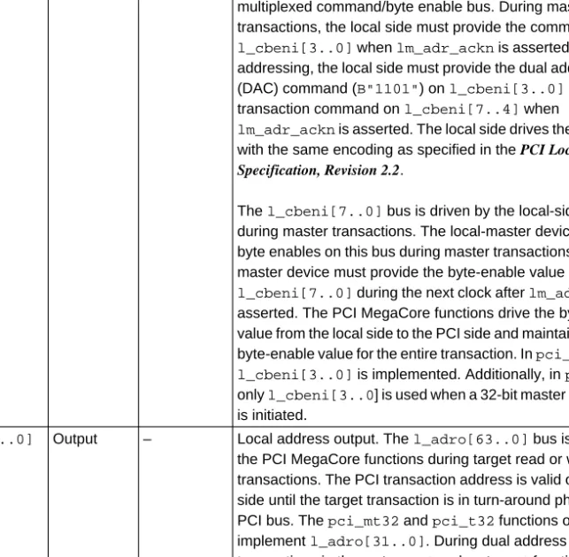
Table 1. PCI MegaCore Directories (Part 1 of 2)
Directory Description
\bin Contains the set_constraint utility that generates constraint files for the Altera software to incorporate your custom design hierarchy. For the Quartus software, the Compiler Settings File (.csf) and Entity Settings File (.esf) are generated. For the MAX+PLUS II software, the Assignment & Configuration File (.acf) is generated. The generated files contain all necessary assignments to ensure that all PCI timing requirements are met.
\lib Contains encrypted lower-level design files. After installing the MegaCore function, you should set a user library in the Altera software that points to this directory. This library allows you to access all of the necessary MegaCore files.
\<pci function> Contains the MegaCore function files.
\<pci function>\APEX Contains the MegaCore function files specific to Altera APEX devices. For more information, refer to the readme file in this directory.
\<pci function>\APEX\csf The \csf directory contains CSFs and ESFs for targeting Altera APEX devices.
These constraint files contain all necessary assignments to meet PCI timing requirements. By using the set_constraint utility, you can annotate the assignments in one of these CSF/ESF sets for your project. For more information, refer to the readme file in this directory.
\<pci function>\APEX\examples The \examples directory has subdirectories containing examples for APEX device/package combinations. Each subdirectory contains a Block Design File (.bdf), a CSF, and an ESF. The \examples directory also contains the \simtop subdirectory, which contains a BDF and Simulator Settings File (.ssf) that can be used to perform compilation and functional simulation of the PCI MegaCore function. For more information, refer to the readme file in the \examples directory.
\<pci core>\APEX\sim The \vwf directory contains Vector Waveform Files (.vwf) that show different
PCI protocol transactions that can be used to verify the functionality of the Altera PCI MegaCore function. For more information, refer to the readme file in this directory.
\<pci core>\doc Contains documentation for the MegaCore function.
Quartus
Walk-Through
This section describes the PCI design flow using an Altera PCI MegaCore function and the Quartus development system (see Figure 1).
Figure 1. Example PCI Design Flow with the Quartus Software
\<pci core>>\FLEX Contains the MegaCore function files specific to Altera FLEX devices. For more information, refer to the readme file in this directory.
\<pci core>\FLEX\acf The \acf directory contains ACFs for targeting Altera FLEX devices. These
constraint files contain all necessary assignments to meet your PCI timing requirements. By using the set_constraint utility, you can annotate the assignments in one of these ACFs for your project. For more information, refer to the readme file in this directory.
\<pci core>\FLEX\examples The \examples directory has subdirectories containing examples for FLEX device/package combinations. Each subdirectory contains a Graphic Design File (.gdf) and an ACF. The \examples directory also contains the \sim_top subdirectory, which contains a GDF and an ACF that can be used to perform functional compilation and simulation of the PCI MegaCore function. For more information, refer to the readme file in this directory.
\<pci core>\FLEX\sim The \scf directory contains Simulator Channel Files (.scf) that show different PCI protocol transactions that can be used to verify the functionality of the Altera PCI MegaCore function. For more information, refer to the readme file in this directory.
Table 1. PCI MegaCore Directories (Part 2 of 2)
Directory Description
Create a Design File
Create a CSF & ESF using the set_constraint utility
Perform Compilation &
Functional Simulation
Use Timing Analyzer to Verify Timing
License the Function &
Getting Started The following instructions assume that:
1
■ You are using an Altera MegaCore function.
■ All files are located in the default directory, c:\megacore. If the files are installed in a different directory on your system, substitute the appropriate path name.
■ You are using a PC; UNIX users should alter the steps as appropriate.
■ You are familiar with the Quartus software.
■ Quartus version 1999.10 or higher is installed in the default location (i.e., c:\quartus).
■ You are using the OpenCore feature to test-drive the function or you have licensed the function.
1 You can use Altera’s OpenCore feature to compile and simulate PCI MegaCore functions, allowing you to evaluate the functions before deciding to license them. However, you must obtain a license from Altera before you can generate programming files.
The sample design process uses the following steps:
1. Create a BDF that instantiates the PCI MegaCore function.
2. Run the set_constraint utility to create a CSF and ESF that contain the necessary assignments for meeting the targeted device’s PCI timing requirements.
3. Perform a compilation and run functional simulations to evaluate and verify the functionality.
4. Examine the timing analysis results to verify that the PCI timing specifications are met.
5. If you have licensed the MegaCore function, configure a targeted Altera APEX device with the completed design.
Design Entry
The following steps explain how to create a BDF that instantiates an Altera PCI MegaCore function.
1 Refer to Quartus Help for detailed instructions on creating and editing block diagrams.
1. Run the Quartus software.
2. Create a new BDF named pci_top.bdf using the schematic shown in the APEX\examples\sim_top directory as an example. You may skip this step by saving the APEX\examples\sim_top\pci_top.bdf as a new design.
3. Using the Quartus software, save your BDF into a new directory (e.g., c:\altr_app). You will be prompted to create a new project with this file. Choose Yes to create a new project.
4. The Quartus New Project wizard will open. Select the present working directory and your new BDF as the project name and top- level design entity. If necessary, change any of the default settings in this dialog box and choose Next.
5. Specify the user library for the Altera PCI MegaCore function as c:\megacore\lib. Add additional design files for your project as necessary and choose Finish.
After you have entered your design, you are ready to annotate PCI- specific assignments to your project using the set_constraint utility.
Run the set_constraint Utility
The set_constraint utility, located in the c:\megacore\bin directory, is used to generate a CSF and an ESF that contain the placement and configuration assignments to meet the PCI timing specifications. For more information on the set_constraint utility, refer to the documentation in the c:\megacore\bin directory.
Generate the files pci_top.csf and pci_top.esf by performing the
following steps (these steps use the Altera pci_mt64 MegaCore function as an example):
1. Close your project in the Quartus software.
2. Run the set_constraint utility by typing the following command at a DOS command prompt:
c:\megacore\bin\set_constraint
Getting Started 3. You are prompted with several questions. Type the following after
1
each question. (The bold text is the prompt text.) Enter the Chip Name:
pci_top9
Enter the Hierarchical Name for the PCI MegaCore Function:
pci_mt64:YY Where:
YY is the instance name for the MegaCore function. In a BDF, it is the name in the lower left-hand corner of the PCI MegaCore symbol.
Type the Path and Name of the Input CSF or ACF:
c:\megacore\pci_mt64\APEX\csf\20K400EF672_66.csf9 Type the Path of the Output CSF:
(e.g., c:\altr_app) c:\altr_app9
1 For a listing of the supported Altera device CSFs, refer to the readme file in the \megacore\pci_mt64\doc directory.
4. After you have generated your CSF and ESF, you are ready to perform compilation to synthesize and place and route your design.
Compilation & Functional Simulation
The following steps explain how to compile and functionally simulate your design.
The default parameter settings of the Altera PCI MegaCore functions instantiate one base address register (BAR). The number of BARs that are instantiated and the size of each BAR’s memory affects the amount of logic that is generated for your design. If the NUMBER_OF_BARS parameter is set to less than 6, the logic for the unused BARs will not be generated.
Each MegaCore function’s simulation files are generated using all 6 BARs, allowing you to further evaluate the functional capabilities of the Altera PCI MegaCore functions. When evaluating the MegaCore function using the functional simulation files contained in the \APEX\sim\vwf directory, set the NUMBER_OF_BARS parameter to a decimal value of 6 and set the individual BAR values to those of
\APEX\examples\sim_top\pci_top.bdf. To change the parameter settings for the MegaCore function, double-click the symbol. You can also single-click the symbol, choose Properties (Edit menu), and choose the Parameters tab.
1 When changing a parameter value, only change the number (i.e., leave the hexadecimal indicator H and quotation marks). If you delete these characters, you will receive a compilation error. In addition, when setting register values, the Quartus software may issue several warning messages indicating that one or more registers are stuck at ground. These warning messages can be ignored.
1. Open your project in the Quartus software and choose the Compile Mode command (Processing menu).
2. Choose Start Compile (Processing menu) to compile your design.
3. When compilation completes, change to Simulate Mode (Processing menu) to functionally simulate your design.
4. In the Quartus Simulator Settings dialog box, choose the Mode tab and select Functional. Click Apply.
5. Choose the Time/Vectors tab and specify c:\megacore\<PCI MegaCore function>\APEX\sim\vwf\<target or master
transactions>.vwf as the source of vector stimuli and choose Apply. 6. Choose Run Simulation (Processing menu) to simulate your design
and view the simulation results. The different simulation files show the behavior of the PCI and local-side signals for different types of transactions.
After you verify that your design is functionally correct, you can use the Quartus timing analysis results to verify that all of the PCI signals in your design meet the PCI timing specifications.
Getting Started
Timing Analysis 1
The following steps explain how to verify the timing results for your design.
1. Choose the Compile Mode command (Processing menu).
2. Open the Compilation Report (Processing menu) and expand the Timing Analysis section.
3. The Quartus software lets you perform the following five types of timing analysis:
■ fMAX: The fMAX results report the maximum clock frequency and identify the longest delay paths between registers.
■ tSU: The tSU results report the setup times of the registers.
■ tH: The tH results report the hold times of the registers.
■ tCO: The tCO results report the clock-to-output delays of the registers.
■ tPD: The tPD results report the combinatorial pin-to-pin delays.
You are now ready to configure your targeted Altera APEX device.
Configuring a Device
After you have compiled and analyzed your design, you are ready to configure your targeted Altera APEX device. If you are evaluating the PCI MegaCore function with the OpenCore feature, you must license the PCI MegaCore function before you can generate configuration files. Altera provides three types of hardware to configure APEX devices.
■ The Altera Stand-Alone Programmer (ASAP2) includes an LP6 Logic Programmer card and a Master Programming Unit (MPU). You should use the PLMJ1213 programming adapter with the MPU to program a serial configuration device, which loads the configuration data to the APEX device during power-up. A Programmer Object File (.pof) is used to program the configuration device. The Altera Stand- Alone Programmer is typically used in the production stage of the design flow.
■ The MasterBlasterTM communications cable is a standard PC serial or USB port hardware interface. An SRAM Object File (.sof) is used to configure the APEX device. The MasterBlaster cable is typically used in the prototyping stage of the design flow.
■ The ByteBlasterMVTM parallel port download cable provides a hardware interface to a standard parallel port. The SOF is used to
f
For more information, refer to the ByteBlasterMV Parallel Port Download Cable Data Sheet and MasterBlaster Serial/USB Communications Cable Data Sheet.Perform the following steps to setup the Quartus configuration interface.
For more information, refer to Quartus Help.
1. Open the Programmer.
2. Click the Setup button.
3. In the Hardware Setup dialog box, select your programming hardware in the Hardware Type box and click OK.
4. Click the Add File button and select your programming filename.
5. Choose the programming mode (JTAG or passive serial). If choosing JTAG, check the Program/Configure box.
6. Click Start to configure the APEX device or EPC2 device using the ByteBlasterMV or MasterBlaster cables.
MAX+PLUS II Walk-Through Overview
This section describes the PCI design flow using an Altera PCI MegaCore function and the MAX+PLUS II development system (see Figure 2).
Figure 2. Example PCI Design Flow with the MAX+PLUS II Software
Create a Design File
Perform Functional Compilation & Simulation
Create an ACF using the set_constraint Utility
Perform Timing Compilation & Analysis
License the Function &
Configure the Devices
Getting Started The following instructions assume that:
1
■ You are using an Altera MegaCore function.
■ All files are located in the default directory, c:\megacore. If the files are installed in a different directory on your system, substitute the appropriate path name.
■ You are using a PC; UNIX users should alter the steps as appropriate.
■ You are familiar with the MAX+PLUS II software.
■ MAX+PLUS II version 9.22 or higher is installed in the default location (i.e., c:\maxplus2).
■ You are using the OpenCore feature to test-drive the function or you have licensed the function.
1 You can use Altera’s OpenCore feature to compile and simulate PCI MegaCore functions, allowing you to evaluate the functions before deciding to license them. However, you must obtain a license from Altera before you can generate programming files.
The sample design process uses the following steps:
1. Create a GDF that instantiates the PCI MegaCore function.
2. Perform functional compilation and simulation to evaluate and verify the functionality.
3. Run the set_constraint utility to create an ACF that contains the necessary assignments for meeting the targeted device’s PCI timing requirements.
4. Perform timing compilation and analysis to verify that the PCI timing specifications are met.
5. If you have licensed the MegaCore function, configure a targeted Altera FLEX device with the completed design.
Design Entry
The following steps explain how to create a GDF that instantiates an Altera MegaCore function.
1 Refer to MAX+PLUS II Help for detailed instructions on how to use the Graphic Editor.
1. Run the MAX+PLUS II software.
2. Specify user libraries for the MegaCore function. Choose User Libraries (Options menu) and specify the directory
c:\megacore\lib.
3. Create a directory to hold your design file, e.g., c:\altr_app.
4. Create a new GDF named pci_top.gdf and save it to your new directory (e.g., c:\altr_app\pci_top.gdf).
5. Choose Project > Set Project to Current File (File menu) and specify the pci_top.gdf file as the current project.
6. Enter the schematic shown in the pci_top.gdf file in the
\examples\sim_top directory. You may skip this step by copying the schematic in the pci_top.gdf file into your pci_top.gdf file in your working directory.
After you have entered your design, you are ready to perform functional simulation to evaluate and verify the functionality.
Functional Compilation/Simulation
The following steps explain how to functionally compile and simulate your design.
1. In the MAX+PLUS II Compiler, turn on Functional SNF Extractor (Processing menu).
2. Click Start to compile your design.
3. In the MAX+PLUS II Simulator, choose Inputs/Outputs (File Menu), specify c:\megacore\<PCI MegaCore function>\sim\scf\<target or master transactions>.scf in the Input box, and click OK.
4. Click Start to simulate your design.
5. Click Open SCF to view the simulation file. The different simulation files show the behavior of the PCI and local-side signals for different types of transactions.
After you have verified that your design is functionally correct, you are ready to synthesize and place-and-route your design. However, you still need to generate an ACF to ensure that all of the PCI signals in your design meet the PCI timing specifications.
Getting Started
Run the set_constraint Utility 1
The set_constraint utility, located in the c:\megacore\bin directory, is used to generate an ACF that contains the placement and configuration assignments to meet the PCI timing specifications. For more information on the set_constraint utility, refer to the documentation in the
c:\megacore\bin directory.
In the previous section, the NUMBER_OF_BARS parameter is set to a decimal value of 6 because the BAR0 through BAR5 parameter settings are based upon the functional simulations in the \sim\scf directory. This setting allows you to evaluate the functionality of the PCI MegaCore function.
The number of BARs that are instantiated and the size of the memory for each BAR instantiated affects the amount of logic that is generated for your design. If the NUMBER_OF_BARS parameter is set to a value less than 6, the logic for the unused BARs will not be generated.
Generate the file pci_top.acf by performing the following steps (these steps use the Altera pci_mt64 MegaCore function as an example):
1. Open pci_top.gdf. Set the following parameters:
NUMBER_OF_BARS= 1, BAR0 = "H"FFF00000"", and TARGET_DEVICE = "EPF10K100EFC484". Double-click the Parameters Field of the PCI symbol. The Edit Ports/Parameters dialog box opens.
1 When changing a parameter value, only change the number (i.e., leave the hexadecimal indicator H and quotation marks). If you delete these characters, you will receive a compilation error.
Additionally, when setting register values, the MAX+PLUS II software may issue several warning messages indicating that one or more registers are stuck at ground. These warning messages can be ignored.
2. Run the set_constraint utility by typing the following command at a DOS command prompt:
c:\megacore\bin\set_constraint 9
You are prompted with several questions. Type the following after each question. (The bold text is the prompt text.)
Enter the Chip Name:
pci_top 9
Enter the Hierarchical Name for the PCI MegaCore Function:
pci_mt64:YY 9 Where:
YY is the instance name for the MegaCore function. In a GDF, it is the number in the lower left-hand corner of the PCI MegaCore symbol.
Type the Path and Name of the Input CSF or ACF:
c:\megacore\pci_mt64\acf\10K100EFC484.acf 9 Type the Path of the Output ACF:
(e.g., c:\altr_app) c:\altr_app9
1 For a listing of the supported Altera device CSFs, refer to the readme file in the \megacore\pci_mt64\doc directory.
3. After you have generated your ACF, you are ready to perform timing compilation to synthesize and place and route your design.
Timing Compilation & Analysis
The following steps explain how to perform timing compilation and analysis.
1. Choose Project > Set Project to Current File (File menu).
2. In the Compiler, turn off the Functional SNF Extractor command (Processing menu).
3. Click Start to begin compilation.
Getting Started 4. After a successful compilation, open the Timing Analyzer. There are
1
three forms of timing analysis you can perform on your design:
■ In the Timing Analyzer, choose Registered Performance (Analysis menu). The Registered Performance Display calculates the maximum clock frequency and identifies the longest delay paths between registers.
■ In the Timing Analyzer, choose Delay Matrix (Analysis menu).
The Delay Matrix Display calculates combinatorial delays, e.g., tCO and tPD.
■ In the Timing Analyzer, choose Setup/Hold Matrix (Analysis menu). The Setup/Hold Matrix Display calculates the setup and hold times of the registers.
You are now ready to configure your targeted Altera FLEX device.
Configuring a Device
After you have compiled and analyzed your design, you are ready to configure your targeted Altera FLEX device. If you are evaluating the PCI MegaCore function with the OpenCore feature, you must license the PCI MegaCore function before you can generate configuration files. Altera provides four types of hardware to configure FLEX devices:
■ The Altera Stand-Alone Programmer (ASAP2) includes an LP6 Logic Programmer card and a Master Programming Unit (MPU). You should use a PLMJ1213 programming adapter with the MPU to program a serial configuration device, which loads the configuration data to the FLEX device during power-up. A Programmer Object File (.pof) is used to program the configuration device. The Altera Stand- Alone Programmer is typically used in the production stage of the design flow.
■ The MasterBlaster communications cable is a standard PC serial or USB port hardware interface. An SRAM Object File (.sof) is used to configure the FLEX device. The MasterBlaster cable is typically used in the prototyping stage of the design flow.
■ The BitBlaster serial download cable is a hardware interface to a standard PC or UNIX workstation RS-232 port. An SRAM Object File (.sof) is used to configure the FLEX device. The BitBlaster cable is typically used in the prototyping stage of the design flow.
■ The ByteBlaster and ByteBlasterMV parallel port download cables provide a hardware interface to a standard parallel port. (The ByteBlaster cable is obsolete and is replaced by the ByteBlasterMV cable.) The SOF is used to configure the FLEX device. The ByteBlaster and ByteBlasterMV cables are typically used in the prototyping stage.
f For more information, refer to the BitBlaster Serial Download Cable Data Sheet, ByteBlaster Parallel Port Download Cable Data Sheet, ByteBlasterMV Parallel Port Download Cable Data Sheet, and MasterBlaster Serial/USB Communications Cable Data Sheet.
Perform the following steps to set up the MAX+PLUS II configuration interface. For more information, refer to MAX+PLUS II Help.
1. Open the Programmer.
2. Choose Hardware Setup (Options menu).
3. In the Hardware Setup dialog box, select your programming hardware in the Hardware Type box and click OK.
4. Choose Select Programming File (File menu) and select your programming filename.
5. Click Program to program a serial configuration device, or click Configure if you are using the BitBlaster, ByteBlaster,
ByteBlasterMV, or MasterBlaster cable to configure a FLEX device.
Using Third- Party EDA Tools
As a standard feature, Altera’s Quartus and MAX+PLUS II software works seamlessly with tools from all EDA vendors, including Cadence, Exemplar Logic, Mentor Graphics, Synopsys, Synplicity, and Viewlogic.
After you have licensed the MegaCore function, you can generate EDIF, VHDL, Verilog HDL, and SDO files from the Altera software and use them with your existing EDA tools to perform functional modeling and post-route simulation of your design.
To simplify the design flow between Altera software and other EDA tools, Altera has developed the Quartus NativeLink Guidelines for use with the Quartus software, and the Altera Commitment to Cooperative
Engineering Solutions (ACCESS) Key Guidelines for use with the MAX+PLUS II software. These guidelines provide complete instructions on how to create, compile, and simulate your design with tools from leading EDA vendors. The guidelines are part of Altera’s ongoing efforts to give you state-of-the-art tools that fit into your design flow, and to enhance your productivity for even the highest-density devices. These guidelines are available on the software installation CD-ROM and on the Altera web site at http://www.altera.com.
The following sections describe how to generate a VHDL or Verilog HDL functional model, and describe the design flow to compile and simulate your custom Altera PCI MegaCore design with a third-party EDA tool.
Getting Started
Generating VHDL & Verilog HDL Functional Models from the 1
Quartus Software
To generate a VHDL or Verilog HDL functional model from the Quartus software, perform the following steps:
1. Create a new project in Quartus using a pci_top.bdf file located in any of the APEX device/package example subdirectories in the
\APEX\examples directory.
2. Choose the third-party EDA tool that you will use for simulation through the EDA Tool Settings dialog box (Project menu).
3. After selecting a simulation tool, you may choose to change the default settings by choosing the Settings tab.
4. After a successful compilation, Quartus will generate a pci_top.vo functional Verilog HDL model or pci_top.vho functional VHDL model of your PCI MegaCore design. Quartus will also generate a pci_top_v.sdo or pci_top_vhd.sdo file containing the timing information.
5. Compile the pci_top.vo or pci_top.vho output files in your third- party simulator to perform functional simulation using Verilog HDL or VHDL.
To use the Quartus NativeLink feature to automatically start your simulation environment, review Quartus Help and the Quartus NativeLink Guidelines on simulating Verilog HDL and VHDL output files for the EDA tool of your choice.
Synthesis Compilation & Post-Routing Simulation with the Quartus Software
To synthesize your design in a third-party EDA tool and perform post-route simulation in the Quartus software, perform the following steps:
1. Create your custom design instantiating a PCI MegaCore function.
2. Synthesize the design using your third-party EDA tool. Your EDA tool should treat the PCI MegaCore instantiation as a black box by either setting attributes or ignoring the instantiation.
For more information on setting compiler options in your third-party
3. After compilation, generate an output netlist file targeting the APEX device family in your third-party EDA tool.
4. Run the set_constraint utility to generate a CSF and ESF for your targeted APEX device. Refer to “Run the set_constraint Utility” on page 8 for more information.
5. Create a new project in Quartus from your EDIF file using the New Project wizard. Add your design file, including the custom
instantiation of the PCI MegaCore function, to the current project.
Add the PCI \lib directory to your User Libraries for the project.
6. Choose EDA Tool Settings (Project menu).
7. In the EDA Tool Settings dialog box, select the EDA tool for your EDIF netlist from the Design Entry/Synthesis Tool drop-down list box. Change the default tool setting through the Settings box as necessary.
8. In the EDA Tool Settings dialog box, select the EDA tool for your simulation from the Simulation Tool drop-down list box. Change the default tool settings through the Settings box as necessary.
9. Make logic option and/or place-and-route assignments for your custom logic using the Assignment Organizer (Tools menu).
10. Compile your design. The Quartus Compiler synthesizes and performs place-and-route on your design, and generates output and programming files.
11. Import your Quartus-generated output files (.edo, .vho, .vo, or .sdo) into your third-party EDA tool for post-route device-level and system-level simulation.
To use the Quartus NativeLink feature to automatically start your EDA tools for synthesis and simulation, review Quartus Help and the Quartus NativeLink Guidelines to setup your project for the EDA tools of your choice.
Getting Started
Generating VHDL & Verilog HDL Functional Models with the 1
MAX+PLUS II Software
To generate a VHDL or Verilog HDL functional model, perform the following steps:
1. In the MAX+PLUS II software, open a pci_top.gdf file located in any of the FLEX device/package example subdirectories in the
\megacore\<Altera PCI MegaCore>\FLEX\examples directory.
2. In the Compiler, ensure that the Functional SNF Extractor command (Processing menu) is turned off.
3. Turn on the Verilog Netlist Writer or VHDL Netlist Writer command (Interfaces menu), depending on the type of output file you want to use in your third-party simulator.
4. Choose Verilog Netlist Writer Settings (Interface menu) if you turned on Verilog Netlist Writer.
5. In the Verilog Netlist Writer Settings dialog box, select either SDF Output File [.sdo] Ver 2.1 or SDF Output File [.sdo] Ver.1.0 and click OK. Selecting one of these options causes the MAX+PLUS II software to generate the files pci_top.vo, pci_top.sdo, and
alt_max2.vo. The pci_top.vo file is the functional model of your PCI MegaCore design, the pci_top.sdo file contains the timing
information, and the alt_max2.vo file contains the functional models of any Altera macrofunctions or primitives.
6. Choose VHDL Netlist Writer Settings (Interface menu) if you turned on VHDL Netlist Writer.
7. In the VHDL Netlist Writer Settings dialog box, select either SDF Output File [.sdo] Ver 2.1 (VITAL) or SDF Output File [.sdo] Ver. 1.0 and click OK. Choosing one of these options causes the MAX+PLUS II software to generate the files pci_top.vho and pci_top.sdo. The pci_top.vho file is the functional model of your PCI MegaCore design, and the pci_top.sdo file contains the timing information.
8. Compile the pci_top.vo or pci_top.vho output files in your third- party simulator to perform functional simulation using Verilog HDL or VHDL.
Synthesis Compilation & Post-Routing Simulation with the MAX+PLUS II Software
To synthesize your design in a third-party EDA tool and perform post-route simulation in the MAX+PLUS II software, perform the following steps:
1. Create your custom design instantiating a PCI MegaCore function.
2. Synthesize the design using your third-party EDA tool. Your EDA tool should treat the PCI MegaCore instantiation as a black box by either setting attributes or ignoring the instantiation.
1 For more information on setting compiler options in your third-party EDA tool, refer to the MAX+PLUS II ACCESS Key Guidelines.
3. After compilation, generate a hierarchical EDIF netlist file in your third-party EDA tool.
4. Open your EDIF file in the MAX+PLUS II software.
5. Run the set_constraint utility to generate an ACF for your targeted FLEX device. Refer to “Run the set_constraint Utility” on page 15 for more information.
6. Set your EDIF file as the current project in the MAX+PLUS II software.
7. Choose EDIF Netlist Reader Settings (Interfaces menu).
8. In the EDIF Netlist Reader Settings dialog box, select the vendor for your EDIF netlist file in the Vendor drop-down list box and click OK.
9. Make logic option and/or place-and-route assignments for your custom logic using the commands in the Assign menu.
10. In the MAX+PLUS II Compiler, make sure Functional SNF Extractor (Processing menu) is turned off.
11. Turn on the Verilog Netlist Writer or VHDL Netlist Writer command (Interfaces menu), depending on the type of output file you want to use in your third-party simulator. Set the netlist writer
Getting Started 12. Compile your design. The MAX+PLUS II Compiler synthesizes and
1
performs place-and-route on your design, and generates output and programming files.
13. Import your MAX+PLUS II-generated output files (.edo, .vho, .vo, or .sdo) into your third-party EDA tool for post-route, device-level, and system-level simulation.
Notes:
Contents
December 1999
®
MegaCore
2
Overview Features ...27 General Description ...28 Compliance Summary...33 PCI Bus Signals...35 Target Local-Side Signals...42 Master Local-Side Signals ...46 Parameters...49 Functional Description ...54 Target Device Signals & Signal Assertion ...54 Master Device Signals & Signal Assertion ...57
®
December 1999, ver. 1
MegaCore
2
Overview
Features...
This section describes the features of the following PCI MegaCore™functions: pci_mt64, pci_mt32, pci_t64, and pci_t32. These functions are parameterized MegaCore functions implementing peripheral component interconnect (PCI) interfaces.
■ Flexible general-purpose interfaces that can be customized for specific peripheral requirements
■ Dramatically shortens design cycles
■ Fully compliant with the PCI Special Interest Group (PCI SIG) PCI Local Bus Specification, Revision 2.2 timing and functional requirements
■ Extensively verified using industry-proven Phoenix Technology test bench
■ Extensively hardware tested using the following hardware and software (see “Compliance Summary” on page 33 for details) – HP E2928A PCI Bus Analyzer and Exerciser
– HP E2920 Computer Verification Tools, PCI series – Altera’s intellectual property (IP) development board
■ Optimized for the APEXTM 20K, FLEX® 10K, and FLEX 6000 architectures
■ 66-MHz compliant with APEX 20KE-1 and FLEX 10KE-1 devices
■ No-risk OpenCoreTM feature allows designers to instantiate and simulate designs in the Quartus and MAX+PLUS II software prior to purchase
■ Supports most PCI commands, including: configuration read/write, memory read/write, I/O read/write, memory read multiple (MRM), memory read line (MRL), and memory write and invalidate (MWI)
■ PCI target features (applies to pci_mt64, pci_mt32, pci_t64, and pci_t32):
– Capabilities list pointer support – Parity error detection
– Up to six base address registers (BARs) with adjustable memory size and type
– Expansion ROM BAR support
– Local side can request a target abort, retry, or disconnect – Local-side interrupt request
■ Configuration registers:
– Parameterized registers: device ID, vendor ID, class code,
...and More Features
– Parameterized default or preset base address (available for all six) and expansion ROM base address
– Non-parameterized registers: command, status, header type, latency timer, cache line size, interrupt pin, interrupt line
■ 64-bit PCI master only features (applies to pci_mt64):
– Initiates 64-bit addressing, using dual-address cycle (DAC) – Initiates 64-bit memory transactions
– Dynamically negotiates 64-bit transactions and automatically multiplexes data on the local 64-bit data bus
■ 64-bit PCI target only features (applies to pci_t64 and pci_mt64):
– 64-bit addressing capable
– Automatically responds to 32- or 64-bit transactions
General Description
The PCI MegaCore functions covered in this document are hardware- tested, high-performance, flexible implementations of PCI interfaces.
These functions handle the complex PCI protocol and stringent timing requirements internally, and their backend interface is designed for easy integration. Therefore, designers can focus their engineering efforts on value-added custom development, significantly reducing time-to-market.
Optimized for Altera® APEX 20K, FLEX 10K, and FLEX 6000 device families, the PCI functions support configuration, I/O, and memory transactions. With the high density of Altera’s devices, designers have ample resources for custom local logic after implementing the PCI interface. The high performance of Altera’s devices also enables these functions to support unlimited cycles of zero-wait-state memory-burst transactions. These functions can run at either 33-MHz or 66-MHz PCI bus clock speeds, thus achieving from 32-Mbps throughput in a 32-bit, 33-MHz PCI bus system up to 528-Mbps throughput in a 64-bit, 66-MHz PCI bus system.
In the pci_mt64 and pci_mt32 functions, the master and target interface can operate independently, allowing maximum throughput and efficient usage of the PCI bus. For instance, while the target interface is accepting zero-wait state burst write data, the local logic may simultaneously request PCI bus mastership, thus minimizing latency.
To ensure timing and protocol compliance, PCI MegaCore functions have been vigorously hardware tested. See “Compliance Summary” on page 33 for more information on the hardware tests performed.
MegaCore
2
Overview As parameterized functions, pci_mt64, pci_mt32, pci_t64, and
pci_t32 have configuration registers that can be modified upon instantiation. These features provide scalability, adaptability, and efficient silicon implementation. As a result, the same MegaCore functions can be used in multiple PCI projects with different requirements. For example, these functions offer up to six BARs for multiple local-side devices. However, some applications require only one contiguous memory range. PCI designers can choose to instantiate only one BAR, which reduces logic cell consumption. After designers define the parameter values, the MAX+PLUS II and Quartus software
automatically and efficiently modifies the design and implements the logic.
This user guide should be used in conjunction with the latest PCI specification, published by the PCI Special Interest Group (SIG). Users should be fairly familiar with the PCI standard before using these functions. Figures 1 through 4 show the block diagrams for pci_mt64, pci_mt32, pci_t64, and pci_t32, respectively. Refer to these figures for signal names and directions for the individual functions.
The functions consist of several blocks:
■ PCI bus configuration register space. This block implements all of the configuration registers required by the PCI Local Bus Specification, Revision 2.2. You can set these registers to your system requirements by setting the parameters provided.
■ Parity checking and generation. This block is responsible for parity checking and generation. It also asserts parity error signals and required status register bits.
■ Target interface control logic. This block controls the operation of the corresponding MegaCore function on the PCI bus in target mode.
■ Master interface control logic. This block controls the PCI bus.
Operation of the corresponding PCI MegaCore function in master mode. This block is only implemented in the pci_mt64 and pci_mt32 functions.
■ Local target control. This block controls the local side interface operation in target mode.
■ Local master control. This block controls the local side interface operation in master mode. This block is implemented only in the pci_mt64 and pci_mt32 functions.
■ Local address/data/command/byte enables. This block multiplexes and registers all the address, data, command, and byte enable signals to the local side interface.
Figure 1. pci_mt64 Functional Block Diagram
PCI Address/
Data Buffer
Parity Checker &
Generator
cache[7..0]
par perrn serrn framen irdyn trdyn devseln stopn gntn reqn
intan ad[63..0]
cben[7..0]
clk rstn idsel
pci_mt64
l_dato[63..0]
l_adro[63..0]
l_beno[7..0]
l_cmdo[3..0]
l_ldat_ackn
lt_rdyn lt_discn lt_abortn lirqn lt_framen lt_ackn lt_dxfrn lt_tsr[11..0]
l_adi[63..0]
l_cbeni[7..0]
lm_req32n lm_lastn lm_rdyn lm_adr_ackn lm_tsr[9..0]
req64n
ack64n
par64
cmd_reg[5..0]
stat_reg[5..0]
lm_req64n
lm_dxfrn
l_hdat_ackn
Local Target Control Local Address/
Data/Command/
Byte Enable Local Master
Control
PCI Target Control PCI Master
Control
Parameterized Configuration
Registers
lm_ackn
MegaCore
2
Overview Figure 2. pci_mt32 Functional Block Diagram
PCI Address/
Data Buffer
Parity Checker &
Generator
cache[7..0]
par perrn serrn framen irdyn trdyn devseln stopn gntn reqn
intan ad[31..0]
cben[3..0]
clk rstn idsel
pci_mt32
l_dato[31..0]
l_adro[31..0]
l_beno[3..0]
l_cmdo[3..0]
lt_rdyn lt_discn lt_abortn lirqn lt_framen lt_ackn lt_dxfrn lt_tsr[11..0]
l_adi[31..0]
l_cbeni[3..0]
lm_req32n lm_lastn lm_rdyn lm_adr_ackn lm_tsr[9..0]
par64
cmd_reg[5..0]
stat_reg[5..0]
lm_dxfrn
Local Target Control Local Address/
Data/Command/
Byte Enable Local Master
Control
PCI Target Control PCI Master
Control
Parameterized Configuration
Registers
lm_ackn
Figure 3. pci_t64 Functional Block Diagram
PCI Address/
Data Buffer
Parity Checker &
Generator par
perrn serrn framen irdyn trdyn devseln stopn intan ad[63..0]
cben[7..0]
clk rstn idsel
pci_t64
l_dato[63..0]
l_adro[63..0]
l_beno[7..0]
l_cmdo[3..0]
l_ldat_ackn
lt_rdyn lt_discn lt_abortn lirqn lt_framen lt_ackn lt_dxfrn lt_tsr[11..0]
l_adi[63..0]
l_cbeni[7..0]
req64n
ack64n
par64
cmd_reg[5..0]
stat_reg[5..0]
l_hdat_ackn
Local Target Control Local Address/
Data/Command/
Byte Enable
PCI Target Control
Parameterized Configuration
Registers
MegaCore
2
Overview Figure 4. pci_t32 Functional Block Diagram
Compliance Summary
The pci_mt64, pci_mt32, pci_t64, and pci_t32 functions are
compliant with the requirements specified in the PCI SIG PCI Local Bus Specification, Revision 2.2 and Compliance Checklist, Revision 2.2. The function is shipped with sample Quartus Vector Waveform Files (.vwf) and MAX+PLUS II Simulator Channel Files (.scf), which can be used to validate the functions. Consult the readme files provided in the
APEX\sim for a complete list and description for the included Quartus files, and the FLEX\sim directory for a complete list and description for the included MAX+PLUS II files.
To ensure PCI compliance, Altera has performed extensive validation of the PCI MegaCore functions. Validation includes both simulation and hardware testing.
PCI Address/
Data Buffer
Parity Checker &
Generator par
perrn serrn framen irdyn trdyn devseln stopn intan ad[31..0]
cben[3..0]
clk rstn idsel
pci_t32
l_dato[31..0]
l_adro[31..0]
l_beno[3..0]
l_cmdo[3..0]
lt_rdyn lt_discn lt_abortn lirqn lt_framen lt_ackn lt_dxfrn lt_tsr[11..0]
l_adi[31..0]
l_cbeni[3..0]
cmd_reg[5..0]
stat_reg[5..0]
Local Target Control Local Address/
Data/Command/
Byte Enable
PCI Target Control
Parameterized Configuration
Registers
The following simulations are covered by the validation suite for the PCI MegaCore functions:
■ PCI SIG checklist simulations
■ Applicable operating rules in PCI specification appendix C, including:
– Basic protocol – Signal stability
– Master and target signals – Data phases
– Arbitration – Latency
– Exclusive access – Device selection – Parity
■ Local-side interface functionality
■ Corner cases of the PCI and local-side interface, such as random wait state insertion
In addition to simulation, Altera performed extensive hardware testing on the functions to ensure robustness and PCI compliance. The test platforms included the HP E2928A PCI Bus Exerciser and Analyzer, the Altera FLEX 10KE PCI development board with an EPF10K100EFC484-1 device configured with the MegaCore function and a reference design, and PCI bus agents such as the host bridge, Ethernet network adapter, and video card. The hardware testing ensures that the PCI MegaCore functions operate flawlessly under the most stringent conditions.
During hardware testing with the HP E2928A PCI Bus Exerciser and Analyzer, various tests are performed to guarantee robustness and strict compliance. These tests include:
■ Memory read/write
■ I/O read/write tests
■ Configuration read/write tests
The tests generate random transaction type and parameters at the PCI and local sides. The HP E2928A PCI Bus Exerciser and Analyzer simulates random behavior on the PCI bus by randomizing transactions with variable parameters such as:
■ Bus commands
■ Burst length
■ Data types
■ Wait states
MegaCore
2
Overview The local side also emulates the variety of conditions where the PCI
Meg