環境センサ(USB型)
環境センサ(USB型)
ユーザーズマニュアル
CDSC-016A
Table of Contents
1. Introduction ... 4 Scope ... 4 1.1. Communication interface ... 4 1.2. Operation mode ... 5 1.3. 1.3.1 Normal mode ... 51.3.2 Acceleration logger mode ... 5
Use case ... 6
1.4. 1.4.1 BLE connection ... 6
1.4.2 Receive advertising data (BLE non-connection) ... 6
1.4.3 USB communication ... 6
2. BLE GATT Services ... 7
Memory Data Service (Service UUID: 0x5000) ... 8
2.1. 2.1.1 Memory index information (Characteristics UUID: 0x5004) ... 10
2.1.2 Request memory index (Characteristics UUID: 0x5005) ... 11
2.1.3 Memory status (Characteristics UUID: 0x5006) ... 12
2.1.4 Memory sensing data (Characteristics UUID: 0x500A) ... 14
2.1.5 Memory calculation data (Characteristics UUID: 0x500B) ... 14
2.1.6 Memory sensing flag (Characteristics UUID: 0x500C) ... 15
2.1.7 Memory calculation flag (Characteristics UUID: 0x500D) ... 15
Latest Data Service (Service UUID: 0x5010) ... 16
2.2. 2.2.1 Latest sensing data (Characteristics UUID: 0x5012) ... 18
2.2.2 Latest calculation data (Characteristics UUID: 0x5013) ... 18
2.2.3 Latest sensing flag (Characteristics UUID: 0x5014) ... 19
2.2.4 Latest calculation flag (Characteristics UUID: 0x5015) ... 19
2.2.5 Latest acceleration status (Characteristics UUID: 0x5016) ... 20
Acceleration Service (Service UUID: 0x5030)... 21
2.3. 2.3.1 Vibration count (Characteristics UUID: 0x5031) ... 25
2.3.2 Request acceleration memory index (Characteristics UUID: 0x5032) ... 26
2.3.3 Acceleration memory status (Characteristics UUID: 0x5033) ... 27
2.3.4 Acceleration memory data [Header] (Characteristics UUID: 0x5034) ... 28
2.3.5 Acceleration memory data [Data] (Characteristics UUID: 0x5034) ... 30
Control Service (Service UUID: 0x5110) ... 33
2.4. 2.4.1 LED setting [normal state] (Characteristics UUID: 0x5111) ... 34
2.4.2 LED setting [event state] (Characteristics UUID: 0x5112) ... 35
2.4.3 LED state [operation] (Characteristics UUID: 0x5113)... 36
2.4.4 Installation offset (Characteristics UUID: 0x5114) ... 37
2.4.5 Advertise setting (Characteristics UUID: 0x5115)... 38
2.4.6 Memory reset (Characteristics UUID: 0x5116) ... 39
2.4.7 Mode change (Characteristics UUID: 0x5117) ... 39
2.4.8 Acceleration logger control (Characteristics UUID: 0x5118) ... 40
2.4.9 Acceleration logger status (Characteristics UUID: 0x5119) ... 42
Time Setting Service (Service UUID: 0x5200) ... 43 2.5.
形 2JCIE-BU01 環境センサ(USB 型) ユーザーズマニュアル (CDSC-016)
2
2.5.3 Memory storage interval (Characteristics UUID: 0x5203) ... 45
Event Setting Service (Service UUID: 0x5210) ... 46
2.6. 2.6.1 Event pattern [Sensor 1] ... 47
2.6.2 Event pattern [Sensor 2] ... 48
2.6.3 Event pattern [Acceleration] ... 48
Information Service (Service UUID: 0x5400) ... 49
2.7. 2.7.1 Error status (Characteristics UUID: 0x5401) ... 50
2.7.2 Installation direction (Characteristics UUID: 0x5402)... 51
2.7.3 FLASH memory status (Characteristics UUID: 0x5403) ... 52
Generic Access Service (Service UUID: 0x1800) ... 53
2.8. 2.8.1 Device name (Characteristics UUID: 0x2A00) ... 54
2.8.2 Appearance (Characteristics UUID: 0x2A01) ... 54
2.8.3 Peripheral preferred connection parameters (Characteristics UUID: 0x2A04) ... 54
2.8.4 Central address resolution (Characteristics UUID: 0x2AA6) ... 55
Device Information Service (Service UUID: 0x180A) ... 56
2.9. 2.9.1 Model number string (Characteristics UUID: 0x2A24) ... 57
2.9.2 Serial number string (Characteristics UUID: 0x2A25) ... 57
2.9.3 Firmware revision string (Characteristics UUID: 0x2A26) ... 58
2.9.4 Hardware revision string (Characteristics UUID: 0x2A27) ... 58
2.9.5 Manufacturer name string (Characteristics UUID: 0x2A28) ... 58
3. BLE Advertising packet ... 59
Sensor data ... 60
3.1. Calculation data ... 61
3.2. Sensor data & Calculation data (Scan rsp) ... 62
3.3. Sensor flag & Calculation flag (Scan rsp) ... 64
3.4. Serial number ... 66 3.5. 4. USB Communication ... 67 Communication specification ... 67 4.1. Communication procedure ... 67 4.2. Frame format ... 68 4.3. 4.3.1 Common frame format ... 68
4.3.2 CRC-16 calculation ... 68
4.3.3 Payload frame format [Command from Host-Controller]... 69
4.3.4 Payload frame format [Normal Response from 2JCIE-BU01] ... 70
4.3.5 Payload frame format [Error Response from 2JCIE-BU01] ... 71
USB original address ... 72
4.4. 4.4.1 Memory data long (Address: 0x500E) ... 73
4.4.2 Memory data short (Address: 0x500F) ... 75
4.4.3 Latest data Long (Address: 0x5021) ... 76
4.4.4 Latest data short (Address: 0x5022) ... 77
4.4.5 Acceleration memory data [Header] (Address: 0x503E) ... 78
4.4.6 Acceleration memory data [Data] (Address: 0x503F) ... 80
BLE common address ... 82
4.5. 4.5.1 Latest memory information (Address: 0x5004) ... 85
4.5.2 Latest sensing data (Address: 0x5012) ... 85
4.5.3 Latest calculation data (Address: 0x5013) ... 86
4.5.5 Latest calculation flag (Address: 0x5015) ... 87
4.5.6 Latest acceleration status (Address: 0x5016) ... 87
4.5.7 Vibration count (Address: 0x5031) ... 88
4.5.8 LED setting [normal state] (Address: 0x5111) ... 88
4.5.9 LED setting [event state] (Address: 0x5112) ... 89
4.5.10 LED setting [operation] (Address: 0x5113) ... 89
4.5.11 Installation offset (Address: 0x5114) ... 90
4.5.12 Advertise setting (Address: 0x5115) ... 91
4.5.13 Memory reset (Address: 0x5116) ... 91
4.5.14 Mode change (Address: 0x5117) ... 92
4.5.15 Acceleration logger control (Address: 0x5118) ... 92
4.5.16 Acceleration logger status (Address: 0x5119) ... 93
4.5.17 Latest time counter (Address: 0x5201) ... 93
4.5.18 Time setting (Address: 0x5202) ... 93
4.5.19 Memory storage interval (Address: 0x5203) ... 94
4.5.20 Event pattern [Sensor 1] (Address: 0x5211 etc.) ... 94
4.5.21 Event pattern [Sensor 2] (Address: 0x5212 etc.) ... 95
4.5.22 Event pattern [Acceleration] (Address: 0x5226 etc.) ... 96
4.5.23 Error status (Address: 0x5401) ... 97
4.5.24 Installation direction (Address: 0x5402) ... 98
4.5.25 Device information (Address: 0x180A) ... 99
5. Data specification ... 101 Output range ... 101 5.1. Event enable/disable ... 103 5.2. Event flag ... 104 5.3. 5.3.1 Simple threshold ... 105 5.3.2 Change threshold ... 106
5.3.3 Average value threshold... 107
5.3.4 Peak to Peak threshold ... 108
5.3.5 Interval difference threshold ... 109
5.3.6 Base difference threshold ... 110
Event threshold ... 111 5.4.
形 2JCIE-BU01 環境センサ(USB 型) ユーザーズマニュアル (CDSC-016) 4 1. Introduction Scope 1.1. 本通信インターフェース説明書は,USB 型環境センサ(2JCIE-BU01)の通信インターフェースについて適用する. Communication interface 1.2. USB 型環境センサは内蔵する無線通信インターフェースにより,スマートフォン,タブレット,Gateway 等(以下,対向機)と Bluetooth® low energy(以下,BLE)による通信,または USB 2.0 による通信が可能である.USB 型環境センサは BLE
の Peripheral の機能を有する.
Table 1 GAP Role
GAP Role
2JCIE-BU01 Peripheral Smartphone,
Operation mode
1.3.
USB 型環境センサは Normal mode, Acceleration logger mode を備えており,用途に応じて選択する.Mode は任意 に変更可能である. 1.3.1 Normal mode 温度,相対湿度,照度,気圧,騒音,eTVOC,eCO2,不快指数,熱中症危険度等のセンシングデータ取得,ま た,加速度センサによる地震/振動判定機能を有し,SI 値,PGA,計測震度相当値を算出する.センシングデータは 任意の間隔で内蔵 FLASH memory に保存することが可能であり,地震/振動発生時は自動的に生加速度データを FLASH memory に保存する. *不快指数: 夏の蒸し暑さを数量的に表現したもの.温度と湿度から換算する. *熱中症危険度: 熱中症の危険度を数量的に表現したもの.温度と湿度から換算する. *SI 値: ある振動が構造物に与える影響を表す指標.震度と相関がある.水平 2 軸の加速度値から換算する. *PGA: ある区間の最大加速度値.水平 2 軸の加速度値を合成して換算する. *計測震度相当値: SI 値から求めた震度に相関した値.
1.3.2 Acceleration logger mode
加速度取得に特化した mode であり,指定された動作周波数,期間分の生加速度データを取得・保存する.SI 値, PGA などの計算は行わない.
形 2JCIE-BU01 環境センサ(USB 型) ユーザーズマニュアル (CDSC-016) 6 Use case 1.4. 代表的な使用例について説明する. 1.4.1 BLE connection
BLE 通信で Central 機器と接続することで,センシングデータの保存・取得,地震発生時の加速度データ取得,LED 点 灯やモード切り替えなどの各種設定を行うことができる.詳細は,2. BLE GATT Services を参照.
Figure 2 BLE connection image
1.4.2 Receive advertising data (BLE non-connection)
対向機に Gateway を採用し,複数台の USB 型環境センサのデータを収集する用途などに適している.Advertising packet は 8 種類あり,センシングデータ取得,加速度データ取得,センサイベント結果などを選択することができる.詳細 は 3. Advertising packet を参照.
Figure 3 BLE non-connection image 1.4.3 USB communication
USB 通信でセンシングデータの保存・取得,地震発生時の加速度データ取得,LED 点灯やモード切替などの各種設定を 行うことができる.基本的なコマンドは BLE connection と同様である.詳細は,4. USB communication を参照.
2. BLE GATT Services
BLE 通信の使用する UUID は下記に示す値とする.Base UUID は太字の XXXX 以外の部分とし, CUSTOM Service の 各 Service UUID, 各 Characteristics ともに共通の値とする.各 Characteristics の 2byte 以上のデータは全てリトルエン ディアンとする.
Base UUID: AB70XXXX-0A3A-11E8-BA89-0ED5F89F718B
Table 2 List of supported GATT Services
Service UUID Service Name Number of Characteristics 0x5000 (CUSTOM) Memory Data Service 7 0x5010 (CUSTOM) Latest Data Service 5 0x5030 (CUSTOM) Acceleration Service 4 0x5110 (CUSTOM) Control Service 9 0x5200 (CUSTOM) Time Setting Service 3 0x5210 (CUSTOM) Event Setting Service 24 0x5400 (CUSTOM) Information Service 3 0x1800 Generic Access Service 4 0x180A Device Information Service 5
形 2JCIE-BU01 環境センサ(USB 型) ユーザーズマニュアル (CDSC-016)
8
Memory Data Service (Service UUID: 0x5000)
2.1.
FLASH memory に保存されているセンシングデータを取得する Service である.
Table 3 List of Characteristics in Memory Data Service
UUID Characteristics Contents Properties Byte R W N
0x5004 Memory index information Memory index の情報 レ 8 0x5005 Request memory index Memory index の指定 レ 9 0x5006 Memory status Memory 読み出しの status レ 11 0x500A Memory sensing data Sensing data 読み出し レ 20 0x500B Memory calculation data Calculation data 読み出し レ 15 0x500C Memory sensing flag Sensing flag 読み出し レ 18 0x500D Memory calculation flag Calculation flag 読み出し レ 11
*Memory data acquisition procedure
USB 型環境センサは Time setting (UUID : 0x5202)に値が書き込まれることで FLASH memory へのデータ保存を開始する. Memory index とは,センシングデータ保存毎に更新される管理番号である.FLASH memory には最大で 60000 回分のセン シングデータ保存する事が可能であり,60000 回分を超えると古いデータから順に自動的消去される.FLASH memory のデータを 読み出すには以下の手順を実施する.
1. Read Memory index information (Characteristics UUID: 0x5004) センシングデータが保存されている Memory index を取得する.
2. Write Request memory index (Characteristics UUID: 0x5005) 読み出すデータを指定する.
3. Read Memory status (Characteristics UUID: 0x5006) 読み出し可能か確認する.
4. Notify Memory sensing data etc. (Characteristics UUID: 0x500A) Notify にてデータ受信を行う.
形 2JCIE-BU01 環境センサ(USB 型) ユーザーズマニュアル (CDSC-016)
10
2.1.1 Memory index information (Characteristics UUID: 0x5004)
FLASH memory に保存されているセンシングデータの index 数を取得する.
Memory index (Latest) – Memory index (Last)間の最大保存データ数は 60000 データであり,Memory index が 60000 を超えると古いデータから順に上書きされる.Memory index (Latest) – Memory index (Last)間のデータのみ 取得することが可能となる.
Table 4 Memory index information format
Byte Field Format Contents
0-3 Memory index (Latest) UInt32 Range: 0x00000001 to 0x7FFFFFFF *0x00000000: Before storage 4-7 Memory index (Last) UInt32
2.1.2 Request memory index (Characteristics UUID: 0x5005)
FLASH memory に保存されているセンシングデータの取得設定を行う.
取得したいデータの Memory index の範囲,Data type を設定することで環境センサは Notify 送信の準備を開始する.
Table 5 Request memory index format
Byte Field Format Contents
0-3 Memory index (Start) UInt32 Range: 0x00000001 to 0x7FFFFFFF *Last index <=Start index
*End index <= Latest index *Start index <= End index 4-7 Memory index (End) UInt32
8 Data type UInt8
0x00: Sensing data 0x01: Calculation data 0x02: Sensing flag 0x03: Calculation flag *Data type 1. Sensing data 温度,相対湿度,照度,気圧,騒音,eTVOC,eCO2 の値を取得する際に選択する. 2. Calculation data 不快指数,熱中症危険度,振動情報等,地震関連の値を取得する際に選択する. 3. Sensing flag 温度,相対湿度,照度,気圧,騒音,eTVOC,eCO2 のイベントフラグを取得する際に選択する. 4. Calculation flag 不快指数,熱中症危険度,振動情報等,地震関連のイベントフラグを取得する際に選択する.
形 2JCIE-BU01 環境センサ(USB 型) ユーザーズマニュアル (CDSC-016)
12
2.1.3 Memory status (Characteristics UUID: 0x5006)
FLASH memory に保存されているセンシングデータの読出状態を取得する.
Request memory index (UUID : 0x5005)でデータ取得要求し,Status が Ready to transfer(0x01)になれば準 備完了となる.指定範囲を誤っている等,送信準備エラーの場合は Status が Error(0x03)となる.
Table 6 Memory status format
Byte Field Format Contents
0 Status UInt8
0x00: Waiting
0x01: Ready to transfer 0x02: Transferring 0x03: Error
1-8 Time counter UInt64 Range: 0x1 to 0xFFFFFFFFFFFFFFFF 9-10 Memory storage interval UInt16 Range: 0x0001 to 0x0E10 (1 to 3600sec)
Unit: 1sec
*Time counter
指定した Memory index(Start)の Time counter が表示される.各データの transfer packet には Time counter の情報は 含まれていないため,Notify 受信したデータの Time counter は対向機にて紐づけることが必要となる.
Example)
Time counter = 0x00010000
Memory storage interval = 0x000A (10sec) Data 1: 0x00010000 (Time counter)
Data 2: 0x0001000A (Time counter + Memory storage interval * 1) Data 3: 0x00010014 (Time counter + Memory storage interval * 2) Data 4: 0x0001001E (Time counter + Memory storage interval * 3) …
*Time setting 更新時の注意点
Memory status では Memory index(Start)の Time counter のみ取得できるため,データの途中で Time setting が更新さ れた場合に識別することができない.Figure 7 のように途中で Time setting が更新された場合,Time counter は 18 の次が 30 となる.Memory index(start)の指定位置が異なると Figure 8, 9 のように異なった Time setting で紐づけすることになる. Time setting を更新する場合は,更新時の Memory index を把握し,Memory index(start)には更新後の値を入力するこ とが必要になる.
Figure 7 Time setting update
Figure 8 Read memory data
形 2JCIE-BU01 環境センサ(USB 型) ユーザーズマニュアル (CDSC-016)
14
2.1.4 Memory sensing data (Characteristics UUID: 0x500A)
FLASH memory に保存されている Sensing data を Notify で取得する.
Request memory index の Data type で Sensing data(0x00)を選択した場合にのみ有効となる.Client Characteristic Configuration Description (CCCD)を Enable にすると Notify 送信が開始される.取得対象の FLASH memory が読み出し失敗になった場合,Memory index の最上位 bit に 1 を立てて送信する.
Table 7 Memory sensing data format
Byte Field Format Contents
0-3 Memory index UInt32 Range: 0x00000001 to 0x7FFFFFFF *If data error, MSB is 1
4-5 Temperature SInt16
Reference: 5.1. Output range 6-7 Relative humidity SInt16
8-9 Ambient light SInt16 10-13 Barometric pressure SInt32 14-15 Sound noise SInt16
16-17 eTVOC SInt16
18-19 eCO2 SInt16
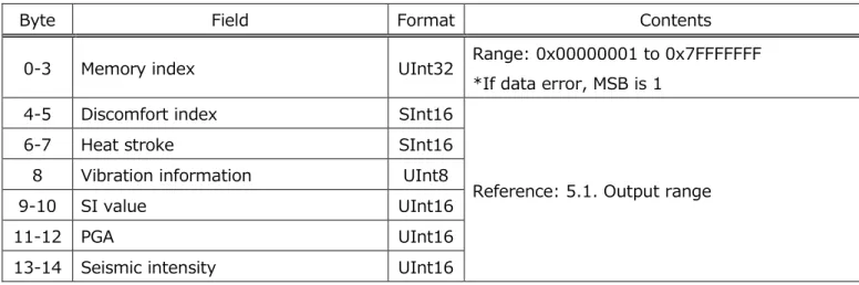
2.1.5 Memory calculation data (Characteristics UUID: 0x500B)
FLASH memory に保存されている Calculation data を Notify で取得する.
Request memory index の Data type で Calculation data(0x01)を選択した場合にのみ有効となる.Client Characteristic Configuration Description (CCCD)を Enable にすると Notify 送信が開始される.取得対象の FLASH memory が読み出し失敗になった場合,Memory index の最上位 bit に 1 を立てて送信する.
Table 8 Memory calculation data format
Byte Field Format Contents
0-3 Memory index UInt32 Range: 0x00000001 to 0x7FFFFFFF *If data error, MSB is 1
4-5 Discomfort index SInt16
Reference: 5.1. Output range 6-7 Heat stroke SInt16
8 Vibration information UInt8 9-10 SI value UInt16
11-12 PGA UInt16
2.1.6 Memory sensing flag (Characteristics UUID: 0x500C)
FLASH memory に保存されている Sensing flag を Notify で取得する.
Request memory index の Data type で Sensing flag(0x02)を選択した場合にのみ有効となる.Client Characteristic Configuration Description (CCCD)を Enable にすると Notify 送信が開始される.取得対象の FLASH memory が読み出し失敗になった場合,Memory index の最上位 bit に 1 を立てて送信する.
Table 9 Memory sensing flag format
Byte Field Format Contents
0-3 Memory index UInt32 Range: 0x00000001 to 0x7FFFFFFF *If data error, MSB is 1
4-5 Temperature flag UInt16
Reference: 5.3. Event flag 6-7 Relative humidity flag UInt16
8-9 Ambient light flag UInt16 10-11 Barometric pressure flag UInt16 12-13 Sound noise flag UInt16 14-15 eTVOC flag UInt16 16-17 eCO2 flag UInt16
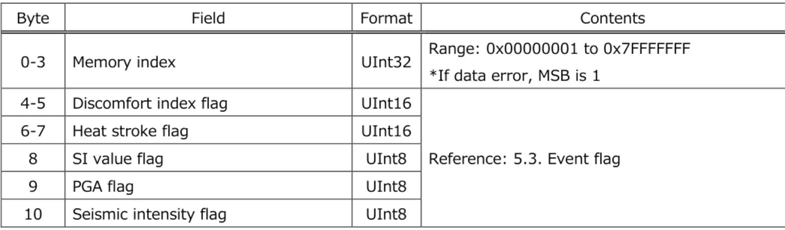
2.1.7 Memory calculation flag (Characteristics UUID: 0x500D)
FLASH memory に保存されている Calculation flag を Notify で取得する.
Request memory index の Data type で Calculation flag(0x03)を選択した場合にのみ有効となる.Client Characteristic Configuration Description (CCCD)を Enable にすると Notify 送信が開始される.取得対象の FLASH memory が読み出し失敗になった場合,Memory index の最上位 bit に 1 を立てて送信する.
Table 10 Memory calculation flag format
Byte Field Format Contents
0-3 Memory index UInt32 Range: 0x00000001 to 0x7FFFFFFF *If data error, MSB is 1
4-5 Discomfort index flag UInt16
Reference: 5.3. Event flag 6-7 Heat stroke flag UInt16
8 SI value flag UInt8
9 PGA flag UInt8
形 2JCIE-BU01 環境センサ(USB 型) ユーザーズマニュアル (CDSC-016)
16
Latest Data Service (Service UUID: 0x5010)
2.2.
センシングデータの最新値を取得できる Service である.
加速度以外のセンシングデータは 1sec 毎に更新され各 Characteristics に反映される. 加速度データは 320msec 毎に更新される.
Table 11 List of Characteristics in Latest Data Service
UUID Characteristics Contents Properties Byte R W N
0x5012 Latest sensing data Sensing data レ レ 17 0x5013 Latest calculation data Calculation data レ レ 18 0x5014 Latest sensing flag Sensing flag レ レ 15 0x5015 Latest calculation flag Calculation flag レ レ 8 0x5016 Latest acceleration status Acceleration status レ レ 15 ※Properties 定義(R : Read,W : Write,N : Notify)
*Sequence number
Sequence number は Memory index と非同期の管理番号であり測定毎(1sec 毎)にインクリメントされる.電源投入後から USB 型環境センサ内部で自動的に更新され 0x00 からスタートする.0xFF まで達すると次は 0x00 となり以降この動作を繰り返 す.
Table 12 Memory index and Sequence number
Description Start trigger Update condition Update interval
Memory index Time setting is set Memory storage Memory storage interval Sequence number Automatic start after boot Measurement 1sec
Figure 10 Memory index and Sequence number [Start-up]
形 2JCIE-BU01 環境センサ(USB 型) ユーザーズマニュアル (CDSC-016)
18
2.2.1 Latest sensing data (Characteristics UUID: 0x5012)
Latest sensing data を取得する.
“Read”の場合は読み出し時点の最新値を返答し,”Notify”を有効にしている場合は更新毎に送信される.
Table 13 Latest sensing data format
Byte Field Format Contents
0 Sequence number UInt8 Range: 0x00 to 0xFF 1-2 Temperature SInt16
Reference: 5.1. Output range 3-4 Relative humidity SInt16
5-6 Ambient light SInt16 7-10 Barometric pressure SInt32 11-12 Sound noise SInt16
13-14 eTVOC SInt16
15-16 eCO2 SInt16
2.2.2 Latest calculation data (Characteristics UUID: 0x5013)
Latest calculation data を取得する.
“Read”の場合は読み出し時点の最新値を返答し,”Notify”を有効にしている場合は更新毎に送信される.
Table 14 Latest calculation data format
Byte Field Format Contents
0 Sequence number UInt8 Range: 0x00 to 0xFF 1-2 Discomfort index SInt16
Reference: 5.1. Output range 3-4 Heat stroke SInt16
5 Vibration information UInt8 6-7 SI value UInt16
8-9 PGA UInt16
10-11 Seismic intensity UInt16 12-13 Acceleration (X-axis) SInt16 14-15 Acceleration (Y-axis) SInt16 16-17 Acceleration (Z-axis) SInt16
2.2.3 Latest sensing flag (Characteristics UUID: 0x5014)
Latest sensing flag を取得する.
“Read”の場合は読み出し時点の最新値を返答し,”Notify”を有効にしている場合は更新毎に送信される.
Table 15 Latest sensing flag format
Byte Field Format Contents
0 Sequence number UInt8 Range: 0x00 to 0xFF 1-2 Temperature flag UInt16
Reference: 5.3. Event flag 3-4 Relative humidity flag UInt16
5-6 Ambient light flag UInt16 7-8 Barometric pressure flag UInt16 9-10 Sound noise flag UInt16 11-12 eTVOC flag UInt16 13-14 eCO2 flag UInt16
2.2.4 Latest calculation flag (Characteristics UUID: 0x5015)
Latest calculation flag を取得する.
“Read”の場合は読み出し時点の最新値を返答し,”Notify”を有効にしている場合は更新毎に送信される.
Table 16 Latest calculation flag format
Byte Field Format Contents
0 Sequence number UInt8 Range: 0x00 to 0xFF 1-2 Discomfort index flag UInt16
Reference: 5.3. Event flag 3-4 Heat stroke flag UInt16
5 SI value flag UInt8
6 PGA flag UInt8
形 2JCIE-BU01 環境センサ(USB 型) ユーザーズマニュアル (CDSC-016)
20
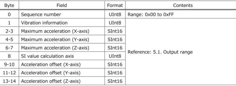
2.2.5 Latest acceleration status (Characteristics UUID: 0x5016)
Latest acceleration status を取得する.
“Read”の場合は読み出し時点の最新値を返答し,”Notify”を有効にしている場合は更新毎に送信される. Acceleration offset は地震/振動非発生時に更新される.
Table 17 Latest acceleration status format
Byte Field Format Contents
0 Sequence number UInt8 Range: 0x00 to 0xFF 1 Vibration information UInt8
Reference: 5.1. Output range 2-3 Maximum acceleration (X-axis) SInt16
4-5 Maximum acceleration (Y-axis) SInt16 6-7 Maximum acceleration (Z-axis) SInt16 8 SI value calculation axis UInt8 9-10 Acceleration offset (X-axis) SInt16 11-12 Acceleration offset (Y-axis) SInt16 13-14 Acceleration offset (Z-axis) SInt16
Acceleration Service (Service UUID: 0x5030)
2.3.
FLASH memory に保存されている加速度データを取得する Service である.
Table 18 List of Characteristics in Acceleration Service
UUID Characteristics Contents Properties Byte R W N
0x5031 Vibration count 地震/振動の積算回数 レ 8 0x5032 Request acceleration memory
index Acceleration memory index 指定 レ 6 0x5033 Acceleration memory status Acceleration memory の読み出し
status レ 3
0x5034 Acceleration memory data Acceleration data 読み出し レ 20 ※Properties 定義(R : Read,W : Write,N : Notify)
形 2JCIE-BU01 環境センサ(USB 型) ユーザーズマニュアル (CDSC-016)
22
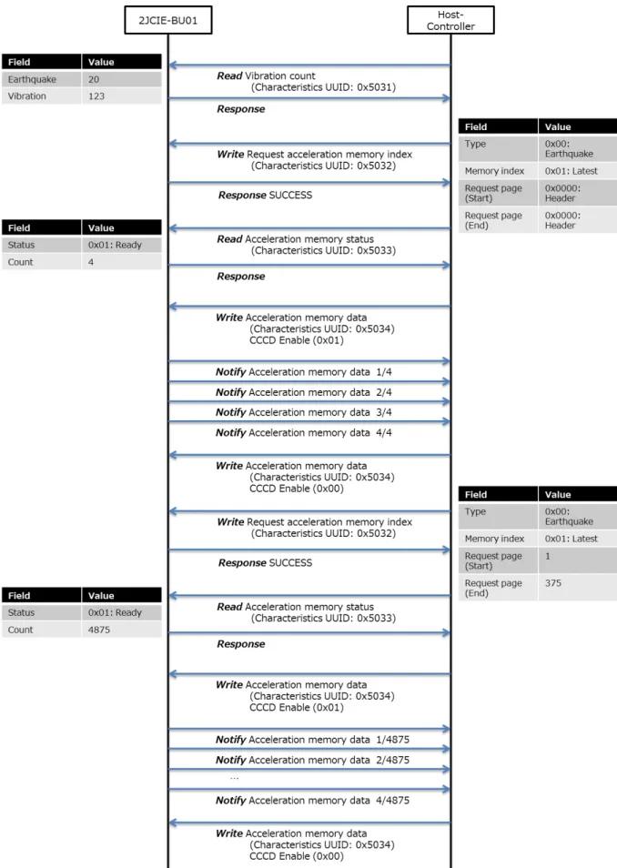
*Acceleration memory data acquisition procedure [Normal mode]
地震/振動は Time setting (UUID : 0x5202)に値が書き込まれる前でも振動を検知すればデータ保存を開始する.取得デー タの format に Time counter があるが Time setting 未書込み時は 0 となる.FLASH memory のデータを読み出すには以下 の手順を実施する.地震データ数は 375page で固定であるが,振動データは振動時間により可変であるため,Header page を 読み出すことで Total page 数を確認する.
1. Read Vibration count (Characteristics UUID: 0x5031) 地震/振動データが保存されているカウント数を取得する.
2. Write Request acceleration memory index (Characteristics UUID: 0x5032) Header page を指定する.
3. Read Acceleration memory status (Characteristics UUID: 0x5033) 読み出し可能か確認する.
4. Notify Memory sensing data etc. (Characteristics UUID: 0x500A) Notify にてデータ受信を行う.
5. Write Request acceleration memory index (Characteristics UUID: 0x5032) 取得する page を指定する.
6. Read Acceleration memory status (Characteristics UUID: 0x5033) 読み出し可能か確認する.
7. Notify Memory sensing data etc. (Characteristics UUID: 0x500A) Notify にてデータ受信を行う.
形 2JCIE-BU01 環境センサ(USB 型) ユーザーズマニュアル (CDSC-016)
24
*Acceleration memory data acquisition procedure [Acceleration logger mode]
Acceleration logger mode で FLASH memory のデータを読み出すには以下の手順を実施する. 1. Write Request acceleration memory index (Characteristics UUID: 0x5032)
取得する page を指定する.
2. Read Acceleration memory status (Characteristics UUID: 0x5033) 読み出し可能か確認する.
3. Notify Memory sensing data etc. (Characteristics UUID: 0x500A) Notify にてデータ受信を行う.
2.3.1 Vibration count (Characteristics UUID: 0x5031)
地震/振動の積算回数を取得する.
Mode 変更,または,Memory reset で Acceleration area を消去した場合に積算回数はリセットされる.
Table 19 Vibration count format
Byte Field Format Contents
0-3 Earthquake count UInt32 Range: 0x00000000 to 0xFFFFFFFF Unit: 1count
形 2JCIE-BU01 環境センサ(USB 型) ユーザーズマニュアル (CDSC-016)
26
2.3.2 Request acceleration memory index (Characteristics UUID: 0x5032)
FLASH memory に保存されている加速度データの取得設定を行う. 1. Normal mode
Data type で取得したいデータ(Earthquake data or Vibration data)を選択し,memory index を指定する. Memory index は,Latest が 1,Last が 10 となる.Header page には,SI value, PGA などの計算結果,また 保存されている加速度生データの page 数を取得することができる.生データを取得する場合は,Header page で Storage total page を確認してから Start page と End page を指定して読み出しを開始する.
Table 20 Request acceleration memory index format [Normal mode]
Byte Field Format Contents
0 Acceleration data type UInt8 0x00: Earthquake data 0x01: Vibration data
1 Request acceleration memory index UInt8 Range: 0x01 to 0x0A (1 to 10)
*0x01: Latest data <---> 0x0A: Last data 2-3 Request page (Start) UInt16 Range: 0x0000 to 0x01FF (0 to 511)
*0x0000: Header page *Start page <= End page 4-5 Request page (End) UInt16
2. Acceleration logger mode
Data type で Logger data を指定し,Start page と End page を指定する.Memory index は使用しないため 0x01 固定となる.Request page (Start)-Request page (End)間で指定できる値は最大 1000page 分とする ため,それ以上のデータを取得する場合は分割する.
Table 21 Request acceleration memory index format [Acceleration logger mode]
Byte Field Format Contents
0 Acceleration data type UInt8 0x02: Logger data 1 Request acceleration memory index UInt8 0x01: Fixed value
2-3 Request page (Start) UInt16 Range: 0x0001 to 0x2800 (1 to 10240) *Start index <= End index
*(Start index - End index) <= 1000 4-5 Request page (End) UInt16
2.3.3 Acceleration memory status (Characteristics UUID: 0x5033)
FLASH memory に保存されている加速度データの読出状態を取得する.
Request acceleration memory index でデータ指定した後,Status が Ready to transfer (0x01)になれば準備完 了となり,これから送信する Notify の総数(Total transfer count)を確認できる.
Table 22 Acceleration memory status format
Byte Field Format Contents
0 Status UInt8
0x00: Waiting
0x01: Ready to transfer 0x02: Transferring 0x03: Error
形 2JCIE-BU01 環境センサ(USB 型) ユーザーズマニュアル (CDSC-016)
28
2.3.4 Acceleration memory data [Header] (Characteristics UUID: 0x5034)
加速度データの Header 情報を”Notify”で取得する.
Normal mode の Header page が指定された場合は,以下の packet が 4 分割され Notify 送信される.取得対象の FLASH memory が読み出し失敗になった場合,Total transfer count の最上位 bit に 1 を立てて送信する.
Table 23 Acceleration memory data format [Header] 1/4
Byte Field Format Contents
0-1 Total transfer count UInt16
Range: 0x0001 to 0x7FFF *Increment for each transmission *If data error, MSB is 1
2-3 Storage total page UInt16 Range: 0x0001 to 0xFFFF
4-7 Earthquakes or vibration count UInt32 Range: 0x00000001 to 0xFFFFFFFF Unit: 1count
8-15 Time counter UInt64 Range: 0x1 to 0xFFFFFFFFFFFFFFFF 16 Earthquake flag UInt8 0x00: Vibration data
0x01: Earthquake data 17 SI value calculation axis UInt8 Reference: 5.1. Output range 18 Reserve for Future Use UInt8 0xFF: Fixed value
19 Reserve for Future Use UInt8 0xFF: Fixed value
Table 24 Acceleration memory data format [Header] 2/4
Byte Field Format Contents
0-1 Total transfer count UInt16
Range: 0x0001 to 0x7FFF
*Increment for each transmission *If data error, MSB is 1
2-3 Page number UInt16 0x0000: Fixed value 4-5 SI value UInt16
Reference: 5.1. Output range
6-7 PGA UInt16
8-9 Seismic intensity UInt16 10-11 Maximum acceleration (X-axis) SInt16 12-13 Maximum acceleration (Y-axis) SInt16 14-15 Maximum acceleration (Z-axis) SInt16 16-17 Temperature SInt16 18-19 Relative humidity SInt16
Table 25 Acceleration memory data format [Header] 3/4
Byte Field Format Contents
0-1 Total transfer count UInt16
Range: 0x0001 to 0x7FFF
*Increment for each transmission *If data error, MSB is 1
2-3 Ambient light SInt16
Reference: 5.1. Output range 4-7 Barometric pressure SInt32
8-9 Sound noise SInt16
10-11 eTVOC SInt16
12-13 eCO2 SInt16
14-15 Discomfort index SInt16 16-17 Heat stroke SInt16
18 Reserve for Future Use UInt8 0xFF: Fixed value 19 Reserve for Future Use UInt8 0xFF: Fixed value
Table 26 Acceleration memory data format [Header] 4/4
Byte Field Format Contents
0-1 Total transfer count UInt16
Range: 0x0001 to 0x7FFF
*Increment for each transmission *If data error, MSB is 1
2-3 Acceleration offset (X-axis) SInt16
Reference: 5.1. Output range 4-5 Acceleration offset (Y-axis) SInt16
6-7 Acceleration offset (Z-axis) SInt16
8 Reserve for Future Use UInt8 0xFF: Fixed value 9 Reserve for Future Use UInt8 0xFF: Fixed value 10 Reserve for Future Use UInt8 0xFF: Fixed value 11 Reserve for Future Use UInt8 0xFF: Fixed value 12 Reserve for Future Use UInt8 0xFF: Fixed value 13 Reserve for Future Use UInt8 0xFF: Fixed value 14 Reserve for Future Use UInt8 0xFF: Fixed value 15 Reserve for Future Use UInt8 0xFF: Fixed value 16 Reserve for Future Use UInt8 0xFF: Fixed value 17 Reserve for Future Use UInt8 0xFF: Fixed value 18 Reserve for Future Use UInt8 0xFF: Fixed value 19 Reserve for Future Use UInt8 0xFF: Fixed value
形 2JCIE-BU01 環境センサ(USB 型) ユーザーズマニュアル (CDSC-016)
30
2.3.5 Acceleration memory data [Data] (Characteristics UUID: 0x5034)
加速度データの Data 情報を”Notify”で取得する.
Normal mode の Data page が指定された場合,または Acceleration logger mode が指定された場合は,以下の packetが13分割されNotify送信される.取得対象のFLASH memoryが読み出し失敗になった場合,Total transfer count の最上位 bit に 1 を立てて送信する.Acceleration logger mode では,SI value,PGA,Seismic intensity, Maximum acceleration は計算対象外となるため出力は 0x0000 固定となる.
Table 27 Acceleration memory data format [Data] 1/13
Byte Field Format Contents
0-1 Total transfer count UInt16
Range: 0x0001 to 0x7FFF
*Increment for each transmission *If data error, MSB is 1
2-3 Page number UInt16
[Normal mode]
Range: 0x0001 to 0x01FF (1 to 511) [Acceleration logger mode]
Range: 0x0001 to 0x2800 (1 to 10240) 4-5 SI value UInt16
[Normal mode]
Reference: 5.1. Output range [Acceleration logger mode] 0x0000: Fixed value
6-7 PGA UInt16
8-9 Seismic intensity UInt16 10-11 Maximum acceleration (X-axis) SInt16 12-13 Maximum acceleration (Y-axis) SInt16 14-15 Maximum acceleration (Z-axis) SInt16 16-17 Temperature SInt16
Reference: 5.1. Output range 18-19 Relative humidity SInt16
Table 28 Acceleration memory data format [Data] 2/13
Byte Field Format Contents
0-1 Total transfer count UInt16
Range: 0x0001 to 0x7FFF
*Increment for each transmission *If data error, MSB is 1
2-3 Ambient light SInt16
Reference: 5.1. Output range 4-7 Barometric pressure SInt32
8-9 Sound noise SInt16
10-11 eTVOC SInt16
12-13 eCO2 SInt16
14-15 Discomfort index SInt16 16-17 Heat stroke SInt16
18 Reserve for Future Use UInt8 0xFF: Fixed value 19 Reserve for Future Use UInt8 0xFF: Fixed value
Table 29 Acceleration memory data format [Data] 3/13 to 12/13
Byte Field Format Contents
0-1 Total transfer count UInt16
Range: 0x0001 to 0x7FFF
*Increment for each transmission *If data error, MSB is 1
2-3 Acceleration (X-axis) SInt16
Reference: 5.1. Output range 4-5 Acceleration (Y-axis) SInt16
6-7 Acceleration (Z-axis) SInt16 8-9 Acceleration (X-axis) SInt16 10-11 Acceleration (Y-axis) SInt16 12-13 Acceleration (Z-axis) SInt16 14-15 Acceleration (X-axis) SInt16 16-17 Acceleration (Y-axis) SInt16 18-19 Acceleration (Z-axis) SInt16
形 2JCIE-BU01 環境センサ(USB 型) ユーザーズマニュアル (CDSC-016)
32
Table 30 Acceleration memory data format [Data] 13/13
Byte Field Format Contents
0-1 Total transfer count UInt16
Range: 0x0001 to 0x7FFF
*Increment for each transmission *If data error, MSB is 1
2-3 Acceleration (X-axis) SInt16
Reference: 5.1. Output range 4-5 Acceleration (Y-axis) SInt16
6-7 Acceleration (Z-axis) SInt16 8-9 Acceleration (X-axis) SInt16 10-11 Acceleration (Y-axis) SInt16 12-13 Acceleration (Z-axis) SInt16
14 Reserve for Future Use UInt8 0xFF: Fixed value 15 Reserve for Future Use UInt8 0xFF: Fixed value 16 Reserve for Future Use UInt8 0xFF: Fixed value 17 Reserve for Future Use UInt8 0xFF: Fixed value 18 Reserve for Future Use UInt8 0xFF: Fixed value 19 Reserve for Future Use UInt8 0xFF: Fixed value
Control Service (Service UUID: 0x5110)
2.4.
各種設定を実施する Service である.
Table 31 List of Characteristics in Control Service
UUID Characteristics Contents Properties Byte R W N
0x5111 LED setting [normal state] RGB color setting [normal state] レ レ 5 0x5112 LED setting [event state] RGB color setting [event state] レ レ 5 0x5113 LED state [operation] RGB color setting [operation] レ レ 3 0x5114 Installation offset Offset correction レ レ 13 0x5115 Advertising setting Interval and mode setting レ レ 3 0x5116 Memory reset Memory reset レ 1 0x5117 Mode change Mode change レ レ 1 0x5118 Acceleration logger control 加速度ロガーモード 測定開始コマンド レ 7 0x5119 Acceleration logger status 加速度ロガーモード Status レ 3 ※Properties 定義(R : Read,W : Write,N : Notify)
形 2JCIE-BU01 環境センサ(USB 型) ユーザーズマニュアル (CDSC-016)
34
2.4.1 LED setting [normal state] (Characteristics UUID: 0x5111)
通常時の LED 表示状態を取得または設定する.
Normally ON (0x01)の場合は Intensity of LED で設定した RGB(Red, Green, Blue)の強度により表示する色を指 定する.255 段階で 255 が最大,全て 255(0xFF)で白色,全て 0(0x00)で点灯無しとなる.Scales を選択した場合は センサ出力に応じて自動的に色が変化する.設定値は FLASH memory に保存され,電源 ON/OFF でも保持される. FLASH 書込みが完了したことを確認するため,”Write”実行後は必ず FLASH memory status (Characteristics UUID: 0x5403)を確認する.
Table 32 LED setting [normal state] format
Byte Field Format Contents
0-1 Display rule (normal state) UInt16
0x0000: Normally OFF 0x0001: Normally ON
0x0002: Temperature value scales 0x0003: Relative humidity value scales 0x0004: Ambient light value scales
0x0005: Barometric pressure value scales 0x0006: Sound noise value scales
0x0007: eTVOC value scales 0x0008: SI value scales 0x0009: PGA value scales 2 Intensity of LED (Red) UInt8
Range: 0x00 to 0xFF 3 Intensity of LED (Green) UInt8
4 Intensity of LED (Blue) UInt8
Table 33 Upper and lower limits of LED scales
Display rule Sensor type Lower value Upper value Unit 0x0002 Temperature 10.00 35.00 degC 0x0003 Relative humidity 20.00 80.00 %RH
0x0004 Ambient light 0 10000 Lx
0x0005 Barometric pressure 950.000 1050.000 hPa 0x0006 Sound noise 35.00 80.00 dB
0x0007 eTVOC 0 1000 ppb
0x0008 SI value 0 60.0 kine
0x0009 PGA 0 300.0 gal
2.4.2 LED setting [event state] (Characteristics UUID: 0x5112)
イベント発生時の LED 表示状態を取得または設定する.
イベント発生時は Intensity of LED で設定した RGB(Red, Green, Blue)の強度により点滅する色を指定する.255 段 階で 255 が最大,全て 255(0xFF)で白色,全て 0(0x00)で点灯無しとなる.イベントは bit field 設定のため,複数のイ ベントを同時に設定することが可能である.設定値は FLASH memory に保存され,電源 ON/OFF でも保持される. FLASH 書込みが完了したことを確認するため,”Write”実行後は必ず FLASH memory status (Characteristics UUID: 0x5403)を確認する.
Table 34 LED setting [event state] format
Byte Field Format Contents
0-1 Display rule (event state) UInt16
Bit7: PGA event Bit6: SI value event Bit5: eTVOC event Bit4: Sound noise event
Bit3: Barometric pressure event Bit2: Ambient light event
Bit1: Relative humidity event Bit0: Temperature event 2 Intensity of LED (Red) UInt8
Range : 0x00 to 0xFF 3 Intensity of LED (Green) UInt8
形 2JCIE-BU01 環境センサ(USB 型) ユーザーズマニュアル (CDSC-016)
36
2.4.3 LED state [operation] (Characteristics UUID: 0x5113)
各動作での LED 表示状態を取得または設定する.
Start up は起動後のみ,Error は Error status (Characteristics UUID: 0x5401)のいずれかのエラーが発生している 場合,Connection は BLE 通信で接続した場合に適用される.設定値は FLASH memory に書き込まれ,電源 ON/OFF でも保持される.FLASH 書込みが完了したことを確認するため,”Write”実行後は必ず FLASH memory status (Characteristics UUID: 0x5403)を確認する.
Table 35 LED setting [operation] format
Byte Field Format Contents
0 Start up UInt8 0x00: Rainbow (default) 0x01: BLUE
1 Error UInt8 0x00: NONE (default) 0x01: RED
2 Connection UInt8 0x00: NONE (default) 0x01: GREEN ON 1sec
Figure 15 LED lighting [Start-up] *Priority of LED lighting
LED 点灯は同時にイベント,エラーが発生する可能性があるため,以下の優先順位で点灯する.
Table 36 Priority of LED lighting
Priority Operation 1 (High) Start up 2 Error 3 Event 4 Normal 5 (Low) Connection
2.4.4 Installation offset (Characteristics UUID: 0x5114)
設置後の任意オフセット・ゲイン値を取得または設定する.
Enable にした設置オフセットについて,指定した値を加算/減算することが可能である.Ambient light のみ Gain 補正で あり,生出力に対して一定の倍率を掛けることができる.設定値は FLASH memory に書き込まれ,電源 ON/OFF でも保 持 さ れ る . FLASH 書込み が 完 了 した こ とを 確 認 す る ため , ”Write” 実行 後 は 必ず FLASH memory status (Characteristics UUID: 0x5403)を確認する.
Table 37 Installation offset format
Byte Field Format Contents
0 Installation offset enable/disable UInt8
Bit4: Sound noise offset enable
Bit3: Barometric pressure offset enable Bit2: Ambient light gain enable
Bit1: Relative humidity offset enable Bit0: Temperature offset enable 1-2 Temperature installation offset SInt16
Range: 0xD8F0 to 0x2710 (-10000 to 10000) Unit: 0.01degC
Default: 0x0000 (0.00degC) 3-4 Relative humidity installation offset SInt16
Range: 0xD8F0 to 0x2710 (-10000 to 10000) Unit: 0.01%RH
Default: 0x0000 (0.00%RH) 5-6 Ambient light installation gain SInt16
Range: 0x0000 to 0x2710 (0 to 10000) Unit: 0.001
Default: 0x0000 (0.000) 7-10 Barometric pressure installation
offset SInt32
Range: 0xFFF0BDC0 to 0x000F4240 (-1000000 to 1000000)
Unit: 0.001hPa
Default: 0x0000 (0.000hPa) 11-12 Sound noise installation offset SInt16
Range: 0xD8F0 to 0x2710 (-10000 to 10000) Unit: 0.01dB
Default: 0x0000 (0.00dB) Example)
Installation offset enable/disable = 0x01 Temperature installation offset = -5.00degC Temperature raw value = 25.65 degC ↓
形 2JCIE-BU01 環境センサ(USB 型) ユーザーズマニュアル (CDSC-016)
38
2.4.5 Advertise setting (Characteristics UUID: 0x5115)
BLE advertising の送信間隔,Data type を取得または設定する.
Advertising の Packet 構成は,3. BLE Advertising packet 参照のこと.Advertising mode で Reserved for Future Use (0x06 to 0x08)が選択された場合は,Sensor data (0x01)の Advertising packet が選択される.設 定値は FLASH memory に保存され,電源 ON/OFF でも保持される.FLASH 書込みが完了したことを確認するた め,”Write”実行後は必ず FLASH memory status (Characteristics UUID: 0x5403)を確認する.
Table 38 Advertise setting format
Byte Field Format Contents
0-1 Advertising interval UInt16
Range: 0x00A0 to 0x4000 (100ms to 10.24s) Unit: 0.625ms
Default: 0x00A0 (100ms)
2 Advertising mode UInt8
0x01: Sensor data (default) 0x02: Calculation data
0x03: Sensor data & Calculation data (Scan rsp) 0x04: Sensor flag & Calculation flag (Scan rsp) 0x05: Serial number
0x06: Reserve for Future Use 0x07: Reserve for Future Use 0x08: Reserve for Future Use
2.4.6 Memory reset (Characteristics UUID: 0x5116)
該当エリアの FLASH memory データを消去する.
Sensing data area はリングバッファになっており自動的に古いデータは消去されるが,Memory index をリセットしたい場合 は Memory reset により Sensing data area を消去する.Acceleration area は Acceleration logger mode でデ ータを消去する場合に使用する.消去時間は約 2min 間であり LED が BLUE に点灯する.FLASH memory status (Characteristics UUID: 0x5403)を読み出すことでも状態が確認でき,Flash memory erasing (0x04)となる間は 消去中であり,NONE (0x00)になると完了となる.
Table 39 Memory reset format
Byte Field Format Contents
0 Memory reset UInt8 0x01: Sensing data area 0x02: Acceleration area
2.4.7 Mode change (Characteristics UUID: 0x5117)
現在のモードの取得,またはモードを設定する.
Mode 切り替え時は Acceleration area の FLASH memory が消去されるため,Memory reset で Acceleration area を消去することと同じ状態となり,約 2min 間の時間を要する.設定値は FLASH memory に保存され,電源 ON/OFF でも同じ mode で起動する.
Table 40 Mode change format
Byte Field Format Contents
0 Mode change UInt8 0x00: Normal mode (default) 0x01: Acceleration logger mode
形 2JCIE-BU01 環境センサ(USB 型) ユーザーズマニュアル (CDSC-016)
40
2.4.8 Acceleration logger control (Characteristics UUID: 0x5118)
Acceleration logger mode の Log Start/Stop を設定する.
Log stop 実行時は Byte 1 から Byte 6 までの値は Log start 時と同じ値を設定する.Start page/End page はユーザ が任意に設定できるが,書き込み済の page に上書きすると正常データを得られないため,同じ page に書き込む場合は Memory reset を実行する必要がある.ODR 設定と,page 数により保存時間を算出できるため,以下の Logging time から設定を行う.
Table 41 Acceleration logger control format
Byte Field Format Contents
0 Logger condition UInt8 0x00: Log stop 0x01: Log start
1 Range of detection UInt8 0x00: ±2000 gal (fixed value)
2 ODR setting UInt8
0x00: 1 Hz 0x01: 10 Hz 0x02: 25 Hz 0x03: 100 Hz 0x04: 200 Hz 0x05: 400 Hz
3-4 Start page UInt16 Range: 0x0001 to 0x2800 (1 to 10240) Unit: 1 page
5-6 End page UInt16
*Logging time
加速度データ保存時間は以下の計算式から算出する.1page に 32 回の加速度データが保存される.
𝐋𝐋𝐋𝐋𝐋𝐋𝐋 𝐭𝐋𝐭𝐭(𝐬𝐭𝐬) = 𝟑𝟑 × 𝟏 𝑶𝑶𝑶
�
×
𝒑𝒑𝒑𝒑
Table 42 Example of acceleration logger setting
Example ODR setting Page Logging time
1 10Hz 10 32sec 2 10Hz 100 320sec 3 100Hz 100 32sec 4 100Hz 1000 320sec 5 400Hz 100 8sec 6 400Hz 1000 80sec
*Sensing data
加速度データ保存に加えて温度,湿度,照度などのセンシングデータもメモリ保存を行う.保存間隔は ODR 設定により異なる.
Table 43 Sensing data update interval
Value ODR setting Update interval
0x00 1Hz 32sec 0x01 10Hz 3.2sec 0x02 25Hz 1.28sec 0x03 100Hz 0.96s 0x04 200Hz 0.96s 0x05 400Hz 0.96s
形 2JCIE-BU01 環境センサ(USB 型) ユーザーズマニュアル (CDSC-016)
42
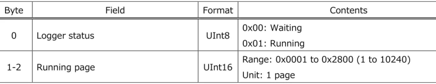
2.4.9 Acceleration logger status (Characteristics UUID: 0x5119)
Acceleration logger mode の Status を取得する.
Logging 実行中は 0x01: Running となる.Running page は Running 中の最終 page を表示する.
Table 44 Acceleration logger status
Byte Field Format Contents
0 Logger status UInt8 0x00: Waiting 0x01: Running
1-2 Running page UInt16 Range: 0x0001 to 0x2800 (1 to 10240) Unit: 1 page
Time Setting Service (Service UUID: 0x5200)
2.5.
時間に関する設定を行う Service である.
Table 45 List of Characteristics in Time Setting Service
UUID Characteristics Contents Properties Byte R W N
0x5201 Time counter デバイスでカウントしている値 レ 8 0x5202 Time setting 設定させたカウント値 レ レ 8 0x5203 Memory storage interval センシングデータ保存間隔 レ レ 2
形 2JCIE-BU01 環境センサ(USB 型) ユーザーズマニュアル (CDSC-016)
44
2.5.1 Latest time counter (Characteristics UUID: 0x5201)
Latest timer counter を取得する.
Latest time は Time setting Characteristics に書き込まれた時点からの経過時間を 1sec 単位で表示する.
Table 46 Latest time counter format
Byte Field Format Contents
0-7 Time counter UInt64 Range: 0x1 to 0xFFFFFFFFFFFFFFFF
2.5.2 Time setting (Characteristics UUID: 0x5202)
環境センサ内部でカウントするオフセット値を取得または設定する.
設定値は FLASH memory に保存されないため,電源 OFF でリセットされる.
Table 47 Time setting format
Byte Field Format Contents
0-7 Time setting UInt64 Range: 0x1 to 0xFFFFFFFFFFFFFFFF *指定する時間は上位システムで任意に決定する.
上図のように書き込む時間を 1 としたときの経過をカウントする,また下図のように UNIX time をベースとした時間設定を行うことも可 能.
2.5.3 Memory storage interval (Characteristics UUID: 0x5203)
FLASH memory にセンシングデータを保存する間隔を取得または設定する.
保存間隔を変更すると Memory index がリセットされるとともに Sensing data area の FLASH memory も消去される. Memory reset で Sensing data area を消去することと同じ状態となり,約 2min 間の時間を要する.設定値は FLASH memory に保存され,電源 ON/OFF でも保持される.FLASH 書込みが完了したことを確認するため,”Write”実行後は 必ず FLASH memory status (Characteristics UUID: 0x5403)を確認する.
Table 48 Memory storage interval format
Byte Field Format Contents
0-1 Memory storage interval UInt16
Range: 0x0001 to 0x0E10 (1 to 3600sec) Unit: 1sec
形 2JCIE-BU01 環境センサ(USB 型) ユーザーズマニュアル (CDSC-016)
46
Event Setting Service (Service UUID: 0x5210)
2.6.
イベント設定を実施する Service である.
Table 49 List of Characteristics in Event Setting Service
UUID Characteristics Contents Properties Byte R W N
0x5211 Temperature [Sensor 1] 温度イベント設定 レ レ 20 0x5212 Temperature [Sensor 2] 温度イベント設定 レ レ 20 0x5213 Relative humidity [Sensor 1] 相対湿度イベント設定 レ レ 20 0x5214 Relative humidity [Sensor 2] 相対湿度イベント設定 レ レ 20 0x5215 Ambient light [Sensor 1] 照度イベント設定 レ レ 20 0x5216 Ambient light [Sensor 2] 照度イベント設定 レ レ 20 0x5217 Barometric pressure [Sensor 1] 気圧イベント設定 レ レ 20 0x5218 Barometric pressure [Sensor 2] 気圧イベント設定 レ レ 20 0x5219 Sound noise [Sensor 1] 音圧イベント設定 レ レ 20 0x521A Sound noise [Sensor 2] 音圧イベント設定 レ レ 20 0x521B eTVOC [Sensor 1] eTVOC イベント設定 レ レ 20 0x521C eTVOC [Sensor 2] eTVOC イベント設定 レ レ 20 0x521D eCO2 [Sensor 1] eCO2 イベント設定 レ レ 20 0x521E eCO2 [Sensor 2] eCO2 イベント設定 レ レ 20 0x521F Discomfort index [Sensor 1] 不快指数イベント設定 レ レ 20 0x5220 Discomfort index [Sensor 2] 不快指数イベント設定 レ レ 20 0x5221 Heat stroke [Sensor 1] 熱中症危険度イベント設定 レ レ 20 0x5222 Heat stroke [Sensor 2] 熱中症危険度イベント設定 レ レ 20 0x5226 SI value [Acceleration] SI 値イベント設定 レ レ 9 0x5227 PGA [Acceleration] PGA イベント設定 レ レ 9 0x5228 Seismic intensity [Acceleration] 震度イベント設定 レ レ 9
2.6.1 Event pattern [Sensor 1]
各種イベントの有効/無効,閾値を取得または設定する.
設定値は FLASH memory に保存され,電源 ON/OFF でも保持される.FLASH 書込みが完了したことを確認するた め,”Write”実行後は必ず FLASH memory status (Characteristics UUID: 0x5403)を確認する.
Table 50 Event pattern [Sensor 1] format
Byte Field Format Contents
0-1 Event enable/disable UInt16 Reference: 5.2. Event enable/disable 2-3 Simple threshold [upper limit] 1 Sint16
Reference: 5.4. Event threshold 4-5 Simple threshold [upper limit] 2 Sint16
6-7 Simple threshold [lower limit] 1 Sint16 8-9 Simple threshold [lower limit] 2 Sint16 10-11 Change threshold [rise] 1 Sint16 12-13 Change threshold [rise] 2 Sint16 14-15 Change threshold [decline] 1 Sint16 16-17 Change threshold [decline] 2 Sint16
18 Reserve for Future Use UInt8 0xFF: Fixed value 19 Reserve for Future Use UInt8 0xFF: Fixed value
形 2JCIE-BU01 環境センサ(USB 型) ユーザーズマニュアル (CDSC-016)
48
2.6.2 Event pattern [Sensor 2]
各種イベントの閾値を取得または設定する.
設定値は FLASH memory に保存され,電源 ON/OFF でも保持される.FLASH 書込みが完了したことを確認するた め,”Write”実行後は必ず FLASH memory status (Characteristics UUID: 0x5403)を確認する.
Table 51 Event pattern [Sensor 2] format
Byte Field Format Contents
0-1 Average value threshold [upper] Sint16
Reference: 5.4. Event threshold 2-3 Average value threshold [lower] Sint16
4-5 Peak to Peak threshold [upper] Sint16 6-7 Peak to Peak threshold [lower] Sint16 8-9 Interval difference threshold [upper] Sint16 10-11 Interval difference threshold [lower] Sint16 12-13 Base difference threshold [upper] Sint16 14-15 Base difference threshold [lower] Sint16 16 Average value count UInt8 17 Peak to Peak count UInt8 18 Interval difference count UInt8 19 Base difference count UInt8
2.6.3 Event pattern [Acceleration]
各種イベントの有効/無効,閾値を取得または設定する.
設定値は FLASH memory に保存され,電源 ON/OFF でも保持される.FLASH 書込みが完了したことを確認するた め,”Write”実行後は必ず FLASH memory status (Characteristics UUID: 0x5403)を確認する.
Table 52 Event pattern [Acceleration] format
Byte Field Format Contents
0 Event enable/disable UInt8 Reference: 5.2. Event enable/disable 1-2 Simple threshold [upper limit] 1 UInt16
Reference: 5.4. Event threshold 3-4 Simple threshold [upper limit] 2 UInt16
5-6 Change threshold [rise] 1 UInt16 7-8 Change threshold [rise] 2 UInt16
Information Service (Service UUID: 0x5400)
2.7.
センサの情報を取得する Service である.
Table 53 List of Characteristics in Information Service
UUID Characteristics Contents Properties Byte R W N
0x5401 Error Status エラー情報 レ 11
0x5402 Installation direction センサ設置方向 レ 1 0x5403 FLASH memory status FLASH memory 状態 レ 1 ※Properties 定義(R : Read,W : Write,N : Notify)
形 2JCIE-BU01 環境センサ(USB 型) ユーザーズマニュアル (CDSC-016)
50
2.7.1 Error status (Characteristics UUID: 0x5401)
センサ及び CPU 異常状態を取得する.
対向機から”Read”すると Error status はクリアされる.
Table 54 Error status format
Byte Field Format Contents
0 Temperature sensor error UInt8
Bit3: Initialization error Bit2: Frozen output
Bit1: Sensing data is out of range Bit0: Communication error 1 Relative humidity sensor error UInt8
2 Ambient light sensor error UInt8 3 Barometric pressure sensor error UInt8 4 Sound noise sensor error UInt8 5 Acceleration sensor error UInt8 6 eTVOC sensor error UInt8 7 eCO2 sensor error UInt8
8 CPU error UInt8
Bit2: Reboot with watchdog Bit1: FLASH memory erase error Bit0: FLASH memory initialization error 9 Reserve for Future Use UInt8 0xFF: Fixed value
2.7.2 Mounting orientation (Characteristics UUID: 0x5402)
設置方向を取得する.
Mounting orientation は加速度センサの振動/地震が非検出時に 320ms 間隔で更新される.
Table 55 Mounting orientation format
Byte Field Format Contents
0 Mounting orientation UInt8 Range: 0x01 to 0x06
形 2JCIE-BU01 環境センサ(USB 型) ユーザーズマニュアル (CDSC-016)
52
2.7.3 FLASH memory status (Characteristics UUID: 0x5403)
FLASH memory の書き込み状態を取得する.
BLE 経由で FLASH memory 書き込みを実行した場合は必ずこの Status 確認を実施する必要がある.書込み直後は Writing (0x01)となり,FLASH memory への書込みが完了すると,Write success (0x02)または Write failure (0x03)となる.対向機から Read すると Status は NONE (0x00)となる.Memory reset (Characteristics UUID: 0x5116)でメモリ消去中の 2min 間は Flash memory erasing (0x04)となり,完了後に NONE (0x00)となる.
Table 56 FLASH memory status format
Byte Field Format Contents
0 FLASH memory status UInt8
0x00: NONE 0x01: Writing 0x02: Write success 0x03: Write failure
0x04: Flash memory erasing
Generic Access Service (Service UUID: 0x1800)
2.8.
Table 57 List of Characteristics in Generic Access Service
UUID Characteristics Contents Properties Byte R W N
0x2A00 Device name Name レ 10 0x2A01 Appearance Category レ 2
0x2A04 Peripheral preferred connection parameters
Minimum connection
interval
レ 2Maximum connection
interval
レ 2Slave latency
レ 2Connection supervision
timeout multiplier
レ 2 0x2AA6 Central address resolution Central address resolution形 2JCIE-BU01 環境センサ(USB 型) ユーザーズマニュアル (CDSC-016)
54
2.8.1 Device name (Characteristics UUID: 0x2A00) Table 58 Device name format
Byte Field Format Contents
0 Name Utf8s “R” 0x52 1 “b” 0x62 2 “t” 0x74 3 “-“ 0x2D 4 “S” 0x53 5 “e” 0x65 6 “n” 0x6E 7 “s” 0x73 8 “o” 0x6F 9 “r” 0x72
2.8.2 Appearance (Characteristics UUID: 0x2A01) Table 59 Appearance format
Byte Field Format Contents
0-1 Category 16bit 0: Unknown
2.8.3 Peripheral preferred connection parameters (Characteristics UUID: 0x2A04) Table 60 Peripheral preferred connection parameters format
Byte Field Format Contents
0-1 Minimum connection interval 16bit Unit: 1.25ms
Default: 0x0010(20ms) 2-3 Maximum connection interval 16bit Unit: 1.25ms
Default: 0x0020(40ms) 4-5 Slave Latency 16bit Default: 0x0004(4) 6-7 Connection Supervision Timeout Multiplier 16bit Unit: 10ms
2.8.4 Central address resolution (Characteristics UUID: 0x2AA6) Table 61 Central address resolution support format
Byte Field Format Contents
形 2JCIE-BU01 環境センサ(USB 型) ユーザーズマニュアル (CDSC-016)
56
Device Information Service (Service UUID: 0x180A)
2.9.
Table 62 List of Characteristics in Generic Access Service
UUID Characteristics Contents Properties Byte R W N
0x2A24 Model Number String Model Number レ 10 0x2A25 Serial Number String Serial Number レ 10 0x2A26 Firmware Revision String Firmware Revision レ 5 0x2A27 Hardware Revision String Hardware Revision レ 5 0x2A29 Manufacturer Name String Manufacturer Name レ 5
2.9.1 Model number string (Characteristics UUID: 0x2A24) Table 63 Model number string format
Byte Field Format Contents
0
Model number Utf8s
“2” 0x32 1 “J” 0x4A 2 “C” 0x43 3 “I” 0x49 4 “E” 0x45 5 “-“ 0x2D 6 “B” 0x42 7 “U” 0x55 8 “0” 0x30 9 “1” 0x31
2.9.2 Serial number string (Characteristics UUID: 0x2A25) Table 64 Serial number string format
Byte Field Format Contents
0
Serial number Utf8s
"0"~"3" 0x30~0x33 1 "0"~"9" 0x30~0x39 2 "0"~"9", "X", "Y", "Z" 0x30~0x39, 0x58, 0x59, 0x5A 3 "0"~"9" 0x30~0x39 4 “M” 0x4D 5 "Y" 0x59 6 "0"~"9" 0x30~0x39 7 "0"~"9" 0x30~0x39 8 "0"~"9" 0x30~0x39 9 "0"~"9" 0x30~0x39
形 2JCIE-BU01 環境センサ(USB 型) ユーザーズマニュアル (CDSC-016)
58
2.9.3 Firmware revision string (Characteristics UUID: 0x2A26) Table 65 Firmware revision string format
Byte Field Format Contents
0
Firmware revision Utf8s
"0"~"9" 0x30~0x39 1 "0"~"9" 0x30~0x39
2 "." 0x2E
3 "0"~"9" 0x30~0x39 4 "0"~"9" 0x30~0x39
2.9.4 Hardware revision string (Characteristics UUID: 0x2A27) Table 66 Hardware revision string format
Byte Field Format Contents
0
Hardware revision Utf8s
"0"~"9" 0x30~0x39 1 "0"~"9" 0x30~0x39
2 "." 0x2E
3 "0"~"9" 0x30~0x39 4 "0"~"9" 0x30~0x39
2.9.5 Manufacturer name string (Characteristics UUID: 0x2A28) Table 67 Manufacture name string format
Byte Field Format Contents
0
Manufacture name Utf8s
"O" 0x4F
1 "M" 0x4D
2 "R" 0x52
3 "O" 0x4F
3. BLE Advertising packet
Advertising packet 構成を示す.
Table 68 List of Advertising packet
Description Data type Advertising response Scan
AD Type
Flags(0x01) 16-bit Service UUIDs(0x02) specific(0xFF) Manufacturer Sensor data
(default) 0x01 レ レ レ
Calculation data 0x02 レ レ レ
Sensor data &
Calculation data 0x03 レ レ レ レ
Sensor flag &
Calculation flag 0x04 レ レ レ レ
形 2JCIE-BU01 環境センサ(USB 型) ユーザーズマニュアル (CDSC-016) 60 Sensor data 3.1. Li nk L ay er p ac ke t f or m at ( 47 o ct et s) Preamble (1 octets) Access Address (4 octets) PDU Header (16bits) AdvA (6 octets) Ad ve rt isi ng D at a (3 1 oc te ts) AD 1 0 Length 1 AD Type 0x02 0x01 2 Flags 0x06 AD 2 3 Length 0x17 4 AD Type 0xFF 5 Company ID 0xD5 6 0x02 7 Data Type 0x01 8 Sequence number - 9 Temperature - 10 - 11 Relative humidity - 12 - 13 Ambient light - 14 - 15 Barometric pressure - 16 - 17 - 18 - 19 Sound noise - 20 - 21 eTVOC - 22 - 23 eCO2 - 24 -
25 Reserve for Future Use 0xFF
AD 3 26 Length 0x04 27 AD Type 0x08 28 Local Name "R" 29 "b" 30 "t" CRC
Calculation data 3.2. Li nk La ye r pa ck et fo rm at ( 47 o ct et s) Preamble (1 octets) Access Address (4 octets) PDU Header (16bits) AdvA (6 octets) Ad ve rt isi ng D at a (3 1 oc te ts) AD 1 0 Length 1 AD Type 0x02 0x01 2 Flags 0x06 AD 2 3 Length 0x17 4 AD Type 0xFF 5 Company ID 0xD5 6 0x02 7 Data Type 0x02 8 Sequence number - 9 Discomfort index - 10 - 11 Heat stroke - 12 - 13 Vibration information - 14 SI value - 15 - 16 PGA - 17 - 18 Seismic intensity - 19 - 20 Acceleration (X-axis) - 21 - 22 Acceleration (Y-axis) - 23 - 24 Acceleration (Z-axis) - 25 - AD 3 26 Length 0x04 27 AD Type 0x08 28 Local Name "R" 29 "b" 30 "t"
![Table 25 Acceleration memory data format [Header] 3/4](https://thumb-ap.123doks.com/thumbv2/123deta/7047686.789717/30.892.62.867.158.518/table-acceleration-memory-data-format-header.webp)
![Table 27 Acceleration memory data format [Data] 1/13](https://thumb-ap.123doks.com/thumbv2/123deta/7047686.789717/31.892.66.871.338.789/table-acceleration-memory-data-format-data.webp)
![Table 28 Acceleration memory data format [Data] 2/13](https://thumb-ap.123doks.com/thumbv2/123deta/7047686.789717/32.892.63.866.154.518/table-acceleration-memory-data-format-data.webp)
![Table 50 Event pattern [Sensor 1] format](https://thumb-ap.123doks.com/thumbv2/123deta/7047686.789717/48.892.65.858.292.632/table-event-pattern-sensor-format.webp)
![Table 52 Event pattern [Acceleration] format](https://thumb-ap.123doks.com/thumbv2/123deta/7047686.789717/49.892.58.856.863.1037/table-event-pattern-acceleration-format.webp)
