SPC-16-112 MD-16-076
電気的磁極反転形可変界磁
PM モータの磁極相対位置に関する検討
青山
真大
*, 中島 一清(スズキ) 野口 季彦(静岡大学)
Study on Relative Position of Magnetic Poles of Electrically Reversal Magnetic Pole Type Variable Magnetic Flux PM Motor
Masahiro Aoyama*, Kazukiyo Nakajima (SUZUKI Motor Corporation), Toshihiko Noguchi (Shizuoka University)
This paper describes a variable magnetic flux PM motor in which space harmonic power is utilized for the magnetic flux weakening, automatically. The stator has a toroidally-concentrated winding structure, and the torque generation surfaces are composed of three air-gaps, i.e., a single radial-gap and double axial-gaps. The radial-gap rotor is a consist-magnetized PM rotor and the axial-gap rotors are self-excited wound-field rotor. The magnetomotive force of axial-gap rotor can be retrieved a space harmonic power, which is inevitably generated by a concentrated winding stator. The effects of relative position of magnetic poles between the radial-gap rotor and the axial-gap rotors are conducted through the FE-analysis. Consequently, it is clarified that the relative position of magnetic poles in 60 electrical degree offset against fully reversal magnetic pole position is the most effective position for the variable magnetic flux ratio, and the torque performance. In addition, the self-excitation is experimentally demonstrated with prototype machine.
キーワード:可変界磁,スキュー角,トロイダル巻,自己励磁,マルチギャップ,磁極反転
(Keyword: variable magnetic flux, skew angle, toroidal winding, self-excitation, multi-gap, reversal magnetic pole)
1. はじめに
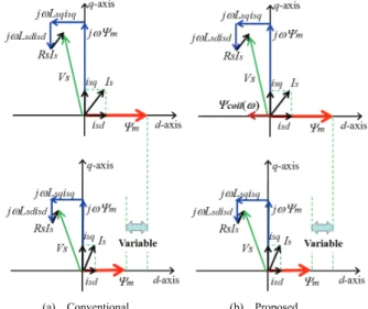
近年,欧州を中心に48V マイルド HEV システムの技術開 発が盛んに行われている。48V システムは高電圧のフル HEV システムに比べれば燃費改善効果が劣るが,一方で車 両重量が軽量なB セグメント以下のコンパクトカーにとっ ては小型軽量で安価なHEV システムとなり,コストメリッ トと燃費改善効果を得やすい。一方で,低電圧駆動のため, 可変界磁可能なクローポール形モータとインバータを組み 合わせた ISG システムが主流となっているが,クローポー ル形モータの場合,スリップリングを用いた他励式のため, 大出力化に伴い従来よりも界磁電流を増やす必要に対して ブラシの摩耗や耐久性が問題となる。さらに鉄塊のロータ 構造のため,鉄損増加による高効率化が困難である。 それらの課題に鑑みて,近年,磁石式同期モータ(PMSM) の高効率エリアと出力拡大を目的に可変界磁モータの検討 が盛んに行われている。図1(a)に示すように磁石磁束Ψmが 可変になることで電機子鎖交磁束の調整と磁石磁束による 鉄損割合が大きい駆動点での高効率化が可能となる。 今日の代表的な研究として,①PMSM の磁石磁力を可変 にするメモリモータ方式,②ロータスキュー角を調整する 方式,③コンシクエントポールの磁化量を調整する方式, ④漏れ磁束を活用する方式が挙げられる(1)-(12)。①の場合, 広い可変界磁レンジで駆動できるため各駆動点で最適なロ ータ界磁を得ることができるが一方でパルス電流を電機子 電流に重畳して駆動中に着減磁を行うため,瞬時的なトル クリプルの発生とモータ出力に対して必要以上に大容量の インバータが必要になる(1)-(4)。②の場合,ロータスキュー角 を機械的に調整するための外部アクチュエータが必要にな(a) Conventional. (b) Proposed.
Fig. 1. Effect of variable magnetic flux technique. (Flux intensifying type).
る(5)(6)。③の場合,静止磁界を発生させるためのコイルと DC/DC コンバータが必要になり且つ,原理的にリラクタン ストルクの活用が困難である(7)-(10)。④の場合,シンプルな 構造でパッシブに可変界磁可能だが可変界磁レンジが狭 く,文献(11)はトルク密度が低い,文献(12)は短絡磁路用の 端板を駆動するアクチュエータが必要という課題がある (11)(12)。 それらの課題に鑑み,筆者らはパルス電流やアクチュエ ータを不要とし,図1(b)に示すように回転速度の増加ととも に自動的に永久磁石磁束に対して反転(スキュー電気角180 deg)した電磁石磁束Ψcoil (ω)を形成することでパッシブに可 変界磁を実現するPM モータを既に提案した(13)。本稿では, 磁石磁極と電磁石磁極の磁極相対位置(スキュー電気角180 deg を変更)に対するモータ性能との関係について,電磁界 解析により性能予測を行い,自励の実機検証を行ったので 報告する。
2. 提案モータの構造
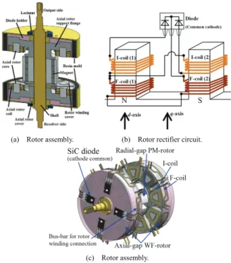
図 2 に提案モータの全体構造を示す。集中巻トロイダル ステータのラジアルギャップ面にPM ロータ,アキシャルギ ャップ2 面に自励式巻線界磁ロータ(SE-WF ロータ)を配 置している。同図は一例としてPM ロータと SE-WF ロータ の磁極配置を電気角で 180 deg 反転させた構造としている が,本稿ではこの磁極相対位置を変化させたときのモータ 諸性能への影響を検証する。PM ロータの磁極は永久磁石の ため起磁力一定であるが,SE-WF ロータの磁極は集中巻構 造で不可避に発生する第 2 次空間高調波(基本波同期回転 座標上では第3 次時間高調波)を界磁エネルギー源として, ダイオード整流回路により自励するパッシブな可変界磁磁 極(回転速度や電機子起磁力によって変化)となる(14)。集 中巻トロイダルステータコアとSE-WF ロータコア材質は磁 路が3 次元となるため SMC(圧粉鉄心)を用いる。図 3 に 示すように集中巻トロイダルステータは突極を挟んで対向 するコイルに逆方向に電流を流すことで 3 次元的に磁束を 発生させることが可能となる。図 4 にロータ構造を示す。 PM ロータコアは電磁鋼板,SE-WF ロータコアは SMC を用 いる。各ロータはシャフトに機械的に連結され同期速度で 回転する。図4(a)に示すように SE-WF ロータの突極にはフ ラットワイズでα 巻した誘導コイル(I-coil)と界磁コイル (F-coil)を軸方向に積み重ねて取り付け,図 4(b)に示す整 流回路で図 4(c)のバックヨーク側に配置したダイオードと 結線する構成である。第 2 次空間高調波はギャップ近傍に多く鎖交するためI-coil をギャップ面側,F-coil を SE-WF ロ
ータの突極根元側に配置している(14)。
(a) Armature current vectors.
図 5 にトロイダルステータの電機子起磁力に重畳してい る第 2 次空間高調波の磁束ベクトルを示す。この静止座標 系における第2 次空間高調波(基本波同期回転座標上の第 3 次時間高調波)がI-coil に鎖交することで誘導起電力が発生 し,その誘導起電力をダイオード整流してF-coil に界磁電流 を流すことで自己励磁により磁極が形成される。I-coil の誘
(b) Magnetic flux contour and vectors.
Fig. 3. Armature current and magnetic flux vectors.
(c) Rotor assembly.
Fig. 5. Second space harmonic vectors and contour. 導起電力はファラデーの法則に基づくため,回転速度の増 加とともにSE-WF ロータ起磁力が増加していく。その結果, 磁極を反転させて配置した PM ロータの磁束ベクトルと SE-WF ロータの磁束ベクトルが対向して電機子巻線に鎖交 するため,回転速度の増加とともに電機子鎖交磁束を減少 でき,結果として自動的に線間電圧を抑制できる。
3. 電磁界解析による性能予測
表 1 に原理検証機の主要諸元を示す。この条件において 電磁界解析により可変界磁特性の確認を行った。解析は (株)JSOL 製の JMAG-Designer ver.14.1 を用いて正弦波電流 源で解析を行い,鉄損は考慮していない。 〈3.1〉電流位相-トルク特性 図6,図 7 に回転速度 2000 r/min,電機子起磁力 890 ArmsT 一定の励磁条件下でスキュー電気角を0 deg から 180 deg ま で30 deg 毎に変化させたときの電流位相-トルク特性を示 す。ここで図8 に示すように,スキュー電気角 0 deg は PM ロータとSE-WF ロータの極性が一致,スキュー電気角 180 deg は両ロータの極性が反転していることを意味する。電流 位相基準はPM ロータの N 極磁石磁極(d 軸)を 0 deg とし ている。図6 に示すように SE-WF ロータの磁極位置(スキ ュー角)を変化させていくとリラクタンストルク(SE-WF ロータ巻線を開放状態で計算)の電流位相-トルク特性は 振幅が変わらず位相特性がシフトすることが確認できる。 順突極構造のため,スキュー電気角180 deg の結果と 0 deg の結果は同じになる。同図(b)の自励式電磁石トルクも振幅 が変わらず位相特性がシフトすることが確認できる。電磁 石トルクは図 7(b)の SE-WF ロータトルクから図 6(a)の SE-WF ロータのリラクタンストルクを差分することで求め ている。ここで自励式電磁石トルクは図8(d)のスキュー電気 角0 deg のとき PM ロータと極性が一致するため正トルク特 性となり,図8(a)のスキュー電気角 180 deg のときは PM ロ ータと極性反転するため負トルク特性となることが確認で きる。図7(a)の PM ロータトルクの結果から SE-WF ロータ の相対磁極位置の影響を受けていないことが確認できる。3 次元磁路とすることでラジアル面の磁路とアキシャル面の 磁路が直交関係となり,磁気干渉していない。Table I. Specifications of prototype. Number of rotor poles 8 Number of stator slots 12 Motor core outer diameter 120 mm
Air-gap length Axial 0.9 mm Radial 0.7 mm
Axial length of core 51.8 mm (without axial-gap core) 107.6 mm (with axial-gap core) Maximum
magnetomotiveforce 1272 ArmsT (60 s) Number of stator coil-turn 18
Armature winding
connection 4 parallel Number of rotor induction
coil-turn 30 Number of rotor field
coil-turn 30 Armature coil size
(with insulation coating) 5.26 mm×0.56 mm Rotor coil size
(with insulation coating) 2.57 mm×0.47 mm Core material Magnetic steel sheet (radial rotor) SMC (stator and axial rotor)
(a) Reluctance torque. (b) Electromagnet toque.
Fig. 6. Current phase-vs.-pancake-axial-gap rotor torque characteristics with respect to electrical skew angle under 890 ArmsT for 2000 r/min.
(a) Radial-gap rotor torque. (b) Pancake-axial-gap rotor torque.
Fig. 7. Current phase-vs.-torque characteristics with respect to electrical skew angle under 890 ArmsT for 2000 r/min.
(a) Electrical skew angle: 180 deg. (b) Electrical skew angle: 90 deg.
(c) Electrical skew angle: 45 deg. (d) Electrical skew angle: 0 deg.
(b) Armature magnetomotive force 509 ArmsT.
(c) Armature magnetomotive force 890 ArmsT.
(d) Armature magnetomotive force 1272 ArmsT.
Fig. 13. Current phase-vs.-line voltage ratio characteristics with respect to electrical skew angle for 2000 r/min.
(a) With rotor winding rectified. (b) With rotor winding opened.
Fig. 10. Current phase-vs.-torque characteristics with respect to electrical skew angle under 509 ArmsT for 2000 r/min.
(a) With rotor winding rectified. (b) With rotor winding opened.
Fig. 11. Current phase-vs.-torque characteristics with respect to electrical skew angle under 890 ArmsT for 2000 r/min.
(a) With rotor winding rectified. (b) With rotor winding opened.
Fig. 12. Current phase-vs.-torque characteristics with respect to electrical skew angle under 1272 ArmsT for 2000 r/min.
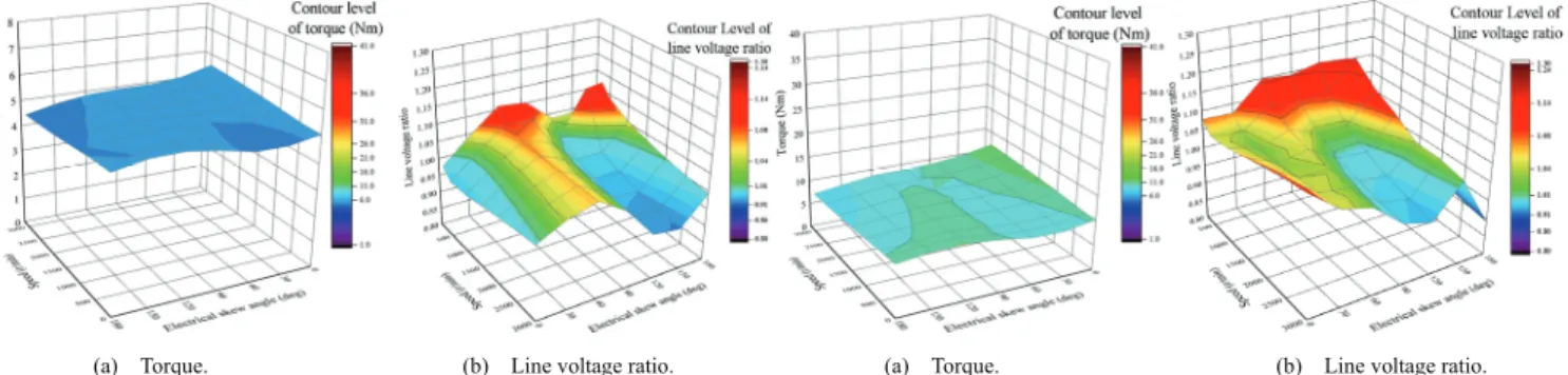
〈3.2〉スキュー角に対する可変速特性 回転速度2000 r/min 一定で、電機子起磁力を変更させたと きのスキュー角に対する電流位相-トルク特性と,比較対 象としてロータ巻線を開放状態にした結果を図9 から図 12 に示す。同図からスキュー角が0 deg(強め界磁)から 180 deg (弱め界磁)に近づくに従い、提案モータはトルクが低下 する傾向になることがわかる。図13 に図 9 から図 12 と同 じ駆動条件における電機子巻線の線間電圧比σを示す。線間 電圧比σは SE-WF ロータ巻線を開放にしたときの線間電圧 Vopenedに対するSE-WF ロータ巻線を整流回路結線したとき
の線間電圧Vclosedの比率 (σ = Vclosed /Vopened)で定義している。
同図より,スキュー角0 deg は強め界磁状態になるためσが
1.0 を上回る結果となる。一方,スキュー角が進角(弱め界
磁状態)していくに従い, σが1.0よりも低い値になることが
(a) Torque. (b) Line voltage ratio. (a) Torque. (b) Line voltage ratio.
Fig. 14. Adjustable speed drive torque and line voltage ratio characteristics Fig. 15. Adjustable speed drive torque and line voltage ratio characteristics with respect to electrical skew angle under 255 ArmsT. with respect to electrical skew angle under 509 ArmsT.
(a) Torque. (b) Line voltage ratio. (a) Torque. (b) Line voltage ratio.
Fig. 16. Adjustable speed drive torque and line voltage characteristics Fig. 17. Adjustable speed drive torque and line voltage ratio characteristics with respect to electrical skew angle under 890 ArmsT. with respect to electrical skew angle under 1272 ArmsT.
キュー角に対してσが比例して減少していくのではなくス キュー角が90 deg から 180 deg の間に極小点が存在すること がわかる。このとき,図9 から図 12 よりスキュー角 180 deg の完全磁極反転よりも線間電圧比σに対するトルクΤ の比η (η=Τ/σ)が最大になるスキュー角のほうがモータ性能(ト ルク密度,可変速特性,効率)を向上できると言える。 次に図14 から図 16 に MTPA 点駆動させたときのスキュ ー角に対する可変速特性を示す。各図より各電機子起磁力 によって線間電圧比σに対するトルクΤ の比ηが最大になる スキュー角が異なることがわかる。可変速トルク特性の拡 大に焦点を当てると電機子起磁力が最大のときに線間電圧 がもっとも抑制されるスキュー角が望ましいと言える。よ って,スキュー角30 deg 刻みで検討した結果においてはス キュー角120 deg が可変速トルク特性拡大に対してもっと も望ましい。図18 にスキュー角 180 deg とスキュー角 120 deg のときの電機子起磁力 1272 ArmsT における可変速特性 (トルク,線間電圧)を示す。同図(a),(b)よりスキュー角 120 deg のほうが線間電圧比σに対するトルク比ηが高く可 変速特性の拡大が可能であることがわかる。同図(c)に同図 (a)のトルク分離をした結果を示す。図 7(a)でスキュー角に 対してラジアルギャップロータ(PM ロータ)のトルクが変 化しないことを示したが一方で,図 6 でスキュー角によっ てアキシャルギャップロータ(SE-WF ロータ)のトルク特 性が変化することを示した。すなわち,スキュー角120 deg
と180 deg で MTPA 点が異なるため,SE-WF ロータがリ
ラクタンストルクのみの0 r/min において図 18(c)で PM ロ
ータトルクが異なる結果となっている。このとき,スキュ
ー角180 deg の MTPA 点が-30 deg であるのに対し,スキ
ュー角120 deg の MTPA 点が 0 deg となる。その結果,電
流位相が強め界磁側から進角する(弱め界磁側)ことにな り,スキュー角120 deg のほうがトルクに対する線間電圧 の抑制が可能となる。
4. 自己励磁の実機検証
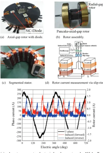
図19(a)~(c)に示す小型原理検証機にて SE-WF ロータの 自励現象の実機検証を行った。ロータ電流は図19(d)に示す ように1 極対分の整流回路をスリップリングを介して接続 することで測定した。図19(d)に回転速度 1800 r/min,電機 子起磁力405 ArmsT,電流位相-20 deg 時のロータ誘導電流 測定結果を示す。同図より.集中巻トロイダルステータで 不可避に発生する第2 次空間高調波(同期回転座標上では 第3 次時間高調波)をアキシャルギャップ面に配置したダ イオード整流形巻線界磁ロータにて自励に活用できること を実機で確認できた。5. まとめ
本稿ではパルス電流やアクチュエータを不要とし,回転 速度の増加とともに自励的に反転磁極(スキュー電気角180 deg)が徐々に形成されることでパッシブに可変界磁可能な モータのPM ロータと WF ロータの磁極相対位置について 検討した。電磁界解析により,磁極相対位置を変更したと きのモータ諸特性を明らかにし反転磁極(180 deg)よりも 磁極相対位置が120 deg の場合のほうがモータ諸特性(ト ルク密度,可変速特性,効率)を向上できることがわかった。また小型試作機にて自励の実機検証を行った。今後は, 試作機により駆動特性を明らかにするとともに,各起磁力 (電機子,永久磁石,自励式電磁石)とアスペクト比のバ ランス調整を行い,可変界磁量の拡大に取組む予定である。
文 献
(1) Ostovic, V.: “Memory Motors”, IEEE Industry Applications Magazine, vol. 9, pp.52-61 (2003)
(2) Ostovic, V. : “Memory Motors – a New Class of Controllable Flux PM Machines for a True Wide Speed Operation”, Proc. of IEEE Industry Applications Society Conference, 2001, vol. 4, pp.2577-2584 (2001)
(3) K. Sakai, K. Yuki, Y. Hashiba, N. Takahashi, K. Yasui, and L. Kovudhikulrungsri: “Principle and Basic Characteristics of Variable Magnetic-Force Memory Motors”, IEEJ Trans. on IA., vol. 131, No. 1 pp.53-60 (2011) (in Japanese)
(4) T. Kato, N. Limsuwan, C. Y. Yu, K. Akatsu, and R. D. Lorenz: “Rare Earth Reduction Using a Novel Variable Magnetomotive Force, Flux Intensified IPM Machine”, IEEE Trans. on IA., vol. 50, No. 3, pp.1748-1756 (May/June, 2016)
(5) T. Nonaka, S. Oga, and M. Ohto: “Consideration about the Drive of
Variable Magnetic Flux Motor”, IEEJ Trans. on IA., vol. 135, No. 5, pp. 451-456 (2015) (in Japanese)
(b) Rotation speed-vs.-line voltages characteristics.
(c) Radial-gap rotor torque and pancake-axial-gap rotor torque.
Fig. 18. Adjustable speed drive characteristics of electrical skew angle 120 deg and 180 deg under 1272 ArmsT.
(e) Armature current and rotor induced currents under 405 ArmsT, and current phase -20 deg for 1800 r/min.
Fig. 19. Prototype machine and experimental test results.
(6) 平本健二・難波雅史・中井英雄・守屋一成・伊藤嘉昭・三浦徹也・山 田堅滋:「回転電機の制御装置及び回転電機制御システム」,特開 (A)2015-177640 (published in 2014) (in Japanese)
(7) T. Mizuno, K. Nagayama, T. Ashikaga, and T. Kobayashi: “Basic Principles and Characteristics of Hybrid Excitation Type Synchronous Machine”, IEEJ Trans. on IA., vol. 115, No. 11, pp.1402-1411 (1995) (in Japanese)
(8) J. A. Tapia, F. Leonardi, and T. A. Lipo: “Consequent-Pole Permanent-Magnet Machine with Extended Field-Weakening Capability”, IEEE Trans. on IA., vol. 39, No. 6, pp.1704-1709 (2003) (9) M. Namba, K. Hiramoto, and H. Nakai: “Novel Variable-Field
Motor with a Three-Dimentional Magnetic Circuit”, IEEJ Trans. on IA., vol. 135, No. 11, pp.1085-1090 (2015) (in Japanese)
(10) T. Ogawa, T. Takahashi, M. Takemoto, H. Arita, A. Daikoku, and S. Ogasawara: “The Consequent-Pole Type Ferrite Magnet Axial Gap Motor with Field Winding for Traction Motor Used in EV”, SAEJ Proc. of EVTeC & APE Japan 2016, No. 20169094 (2016)
(11) T. Kato, M. Minowa, H. Hijikata, and K. Akatsu: “High Efficiency IPMSM Effectively Utilizing Variable Leakage Flux Characteristics”, IEEJ JIASC 2014, No. 3-13, pp. 139-142 (2014) (in Japanese)
(12) I. Urquhart, D. Tanaka, R. Owen, Z. Q. Zhu, J. B. Wang, and D. A. Stone: “Mechanically Actuated Variable Flux IPMSM for EV and HEV Applications”, Proc. of EVS27 International Battery, Hybrid and Fuel Cell Vehicle Symposium 2013, pp. 0684-0695 (2013) (13) M. Aoyama, K. Nakajima, and T. Noguchi: “Proposal of Electrified
Reversal Magnetic Pole Type Variable Magnetic Flux Motor”, IEEJ Annual Meeting 2016, No. 5-043, pp. 77-78 (2016) (in Japanese) (14) M. Aoyama, and T. Noguchi: “Experimental Verification of
Radial-Air-Gap-Type Permanent-Magnet-Free Synchronous Motor Utilizing Space Harmonics with Auxiliary Poles”, IEEJ Trans. on IA., vol. 135, No. 8, pp.869-881 (2015)