Formation and Characterization of Single-Wall Carbon Nanotubes
Shinzo SUZUKI
1,2) 1) Department of Physics, Kyoto Sangyo University, Kyoto 603-8555, Japan 2) Department of Chemistry, Tokyo Metropolitan University, Tokyo 192-0397, JapanAbstract
Different kinds of technique (laser-furnace technique, arc-burning technique, and alcohol- CCVD (ACCVD) technique) were applied for the preparation of single-wall carbon nanotubes (SWNTs), in order to prepare them in high quality and high yield. Based on the experimental find- ings and other investigations using a high-speed video camera combined with a laser furnace appa- ratus, the formation process of SWNTs was discussed.
Introduction
In order to get single-wall carbon nanotubes (SWNTs) in high quality and high yield, several different kinds of technique have been developed and applied. References describe those tech- niques in more details [1-3]. Roughly speaking, these techniques are divided in two categories, i.e., the technique based on the chemical vapor deposition (CVD) and others. In early 1990’s, after the discovery of multi-walled carbon nanotubes by Iijima in the soot obtained with arc-discharge of graphite target [4], this technique has been extensively used for the macroscopic production of carbon nanotubes. Unlike the formation of multi-walled carbon nanotubes (MWNTs), it was found to be essential to use metal catalyst as material incorporated in the composite rods during the preparation of SWNTs. However, the yield of them is relatively low when using He gas atmos- phere, as was usually used for the preparation of fullerenes such as C60 or C70[5], and most of researchers now avoid using this technique, mainly because the raw soot prepared by applying this technique contains not only carbon materials but also lots of metal particles as impurities.
In this paper, the characteristic features of several different techniques for the preparation of SWNTs are briefly described, and then the formation process of SWNTs is considered. The com- mon features seen among those techniques are pointed out, and then discussed based on the
experimental findings using a high-speed video camera and an ICCD system.
1. Characteristic features seen among different techniques used for the prepa- ration of single-wall carbon nanotubes (SWNTs).
Laser furnace technique, first developed by Smalley and others for the preparation of metal- containing endohedral fullerenes [5], was also found to be applicable for the preparation of SWNTs [6]. The advantage of this technique is, as has been described in the previous section, that we can change the experimental parameters independently. Figure 1shows the Raman spec- tra of SWNTs obtained with Ni/Co or Rh/Pd carbon composite rods under different ambient tem- perature, indicating that SWNTs having diameters less than 1nm were preferably prepared in lower ambient temperature condition (T < 1300°C) with Rh/Pd carbon composite rods.
Chemical vapor deposition (CVD) technique has been developed first for the preparation of multi-walled carbon nanotubes. Dai and others reported that, by using the combination of suitable catalyst materials with carbon feedstock (such as methane) under high temperature (850-1000C) one could grow high quality SWNT materials [8-10]. On the other hand, Maruyama et al. reported Fig. 1.Raman spectra in the lower frequency region (100cm-1350cm-1) for SWNTs obtained with Ni/Co (0.6/0.6atom%) (left) and Rh/Pd (1.2/1.2atom%) (right) carbon composite rod by using laser fur- nace technique under different ambient temperature and Ar gas atmosphere.
the successful preparation of SWNTs by using alcohol as carbon feedstock, which was named as ACCVD (alcohol catalytic chemical vapor deposition) technique [11]. This technique has been applied by many researchers, because the experimental setup is quite simple in comparison with that of a laser furnace apparatus or an arc discharge apparatus, and also, it was recognized that SWNTs with less impurity are easily obtained.
In the typical experimental condition of ACCVD technique, metal particles are generated at first, and these metal particles are supported on the limited kinds of porous materials, such as USY zeolite powder [11] or home made porous silica membrane [12]. Then SWNTs are produced by the reaction of alcohol with these metal particles. In order to purify these SWNTs from the raw sample, it is necessary to get rid of these supported materials as well as the metal particles as themselves. Therefore, recent effort of improving CVD technique, (e.g. dip-coating method [13]) has been made to keep away from using these supported materials. Very recently, the formation of mm-scale bulk material consisting mostly of SWNTs (“super-growth” nanotubes [14]) by using such a kind of modified CVD technique, was reported.
SWNTs can be also made with other kind of porous glass particles prepared with a phase sep- aration technique, where borosilicate glass was kept in an oven for several hours [15]. It is well known that one can control the inner diameter of the pore size in the glass systematically and accurately by controlling the ambient temperature and the time during phase separation treat- ments [16]. After heat treatment, porous glass was prepared by etching with chemical treatment.
It is interesting to see whether the yield of SWNTs and the diameter distribution of them are influ- enced or not by using these porous glasses having different inner pore sizes.
Figure 2represents the Raman spectra in lower frequency region (100-350cm-1), which corre- spond to radial breathing mode (RBM) of SWNTs. The upper horizontal axis shows the diameter distribution of SWNT corresponding to the Raman peak position, assuming that the diameter of each SWNT, d(nm), is given by the formula, d = 248 / w, where, w(cm-1) indicates the RBM (Radial Breathing Mode) frequency (The exact formula of das a function of wis still under discus- sion. See e.g., ref. [17]). Figure 2declares that the diameter distribution of SWNTs is invariant in all porous glasses having different pore sizes under the same ambient temperature condition. It is well known that the diameter distribution of SWNTs obtained with ACCVD technique with zeolite is, generally speaking, more widely dispersed than that obtained with arc discharge or laser fur- nace technique, and that distribution shifts toward the larger, as the ambient temperature increas- es. At lower ambient temperature (600°C - 700°C), the diameter distribution of SWNTs prepared with zeolite gives similar diameter distribution of that prepared with porous glass at 850°C, as is shown in Figure 2, except the additional features around 300cm-1, which corresponds to SWNTs
having smaller diameters (of around 0.8nm). In other words, the diameter distribution of SWNTs obtained in this experiment has much sharper distribution than that obtained by usual ACCVD technique with zeolite powder.
Another kind of technique, named as ‘laser-CVD technique’, where metal particles are first generated by laser vaporization of metal or metal alloys and then these metal particles react with alcohol, can also show the preparation of SWNTs [18]. Figure 3indicates the typical TEM image of soot prepared by this technique. The figure clearly shows that lots of SWNTs were synthesized in the form of bundle structures. Figure 4summarizes the Raman spectra of SWNTs prepared by this laser-CVD technique with different ambient temperatures and/or metals. The diameter distri- bution of SWNTs obtained by using this technique resembles to that by using normal ACCVD technique, where the diameter distributions of SWNTs is rather broad at lower ambient tempera- ture, then the mean diameter increases as it becomes higher.
Recent rapid progress of spectrofluometric measurements on SWNTs isolated in aqueous surfactant suspensions has revealed distinct electronic absorption and emission transitions for more than 30different semiconducting nanotube species [19-22]. From the viewpoint of the inves- tigation of the formation process of SWNTs, this finding enables us to see the differences, not only in the diameter distributions of SWNTs, but also in those distributions of ‘chiral index’ which determines the morphological structure of each SWNT prepared in differenet formation condi- Fig. 2.Raman spectra in the lower frequency region (100- 350cm-1) of SWNTs prepared by alcohol CCVD
technique by using porous glasses of different pore sizes at 850∞C [15].
tions. Figure 5shows a typical example, indicating that the ‘chiral index’ distribution seems to converge into only a few species, when the ambient reaction temperature decreases in the case of ACCVD technique, originally shown by Miyauchi et al. [23].
Fig. 4.Raman spectra of untreated SWNTs prepared by the laser-CVD method under various ambient tem- peratures [18]. (a) Low-frequency spectra. Peaks designated by asterisks do not originate from SWNTs. (b) High-frequency Raman spectra. Dotted cuerves indicate the Lorentzian functions and the BWF line shape.
Fig. 3.TEM image of the soot prepared by laser-CVD method under 950°C atmosphere [18].
2. Formation process of SWNTs
Based on the experimental findings and theoretical considerations, the formation process of SWNTs has been extensively discussed since the discovery of carbon nanotubes, and various kinds of model were proposed up to now. The most popular one, especially when considering the formation process of multi-wall carbon nanotubes (MWNTs), is VLS (vapor-liquid-solid) model.
This model was used in order to explain the growth process of carbon whiskers by decomposition of gaseous hydrocarbons on submicron catalytic particles [24]. The characteristic feature of this model is that the metal catalysis is left at the end of growth of carbon whiskers.
In the CVD technique, the generation of SWNTs is usually understood in terms of this VLS model, where carbon atoms are first dissolved into metal particles and a cylindrical structure of SWNT is considered to grow from these metal-carbon mixtures afterwards. When Dai et al. pro- posed such a mechanism first for the growth of SWNTs prepared by using arc-burning technique [25], they showed the transmission electron microscopic image, where the metal alloys were clearly seen to be located at the end of them. Recently, this model was also discussed with in situ observation of TEM image of the growth of carbon nanofibers, where the moving image of metal Fig. 5.Contour plots of fluorescence spectra of SWNTs prepared by ACCVD technique. Each sample was pre- pared under the following ambient temperature condition. (a) 850°C; (b) 750°C; (c) 650°C; (d) HiPco sample (as a reference). The notation (x,y) represents the ‘chiral index’ of each SWNT [23].
particles inside the carbon wall was clearly seen [26].
The size distribution of the SWNTs obtained by using CVD technique depends on the ambi- ent temperature, kinds of metal catalyst, carbon sources, etc. However, the diameter distribution of them obtained by CVD technique is usually broader than those obtained by arc-burning tech- nique or laser furnace technique. It is interesting to investigate whether the size distribution of metal particles supported by these porous glasses is different from others or not, though these metal particles hide inside or around the pore of them. Several experimental studies are now going on in order to clarify this problem [27].
For the formation of SWNTs prepared by using laser furnace technique, another different mechanism, i.e., a ‘scooting’ mechanism is presented by Smalley and others [7]. In this model, a metal atom has an essential role for the elongation of SWNTs. However, other researchers seem to adopt the following idea, that the meal-carbon mixtures are first prepared by laser vaporization of composite rods, then a certain nucleation process and successive elongation process occur [28].
It was recently confirmed that a certain precursor is necessary for the formation of SWNTs, which consists of metal particles and carbon materials, by the following experimental finding [29].
The soot prepared at 550°C and 700°C by laser furnace technique shows the Raman signal due to SWNTs, after post-annealing process. Figure 6clearly shows that the Raman signal due to SWNTs grows after it was heated to 1200°C. Additionally, it is interesting to point out that the soot prepared under lower ambient temperature (T < 550°C), it cannot show any Raman signal due to SWNTs even after annealing process. As was pointed out in the previous section, the round carbon structure seems to start growing above 550°C [30]. Therefore, this experimental finding may suggest that the precursor for SWNTs should include such round carbon structures.
Fig. 6.(left) Raman spectra of the soot prepared by using the laser furnace technique with Ni/Co (0.6/0.6 atom%) carbon composite rods at (a) room temperature (b) 400°C (c) 550°C and (d) 700°C; (right) Raman spectra of each soot after annealing process (1200°C, 2hours) [29].
3. Study by using a high-speed video camera and an ICCD system
As the common feature among the preparation methods for SWNTs, it is well known that metal nanoparticles should coexist with the carbon source. Therefore, in comparison with the for- mation of fullerene species, it is interesting to think when and how the metal particles work dur- ing the course of SWNT formation process. When the metal/alloy nanoparticles and carbon mate- rials are vaporized independently by use of double laser vaporization technique, and are mixed together in the inert gas atmosphere at relatively high temperature, the formation of SWNTs was recognized [31]. Figure 7shows high speed video camera images of the time and spatial evolution of the emission by the plume of the carbon and metal nanoparticles after laser vaporization, each of which was obtained with different time delay (t = -300, -100, 0, +100, +300, and +500µsec, respectively) between two laser systems for double laser vaporization. Figure 7indicates that, though the images of carbon nanoparticles last as long as 1000µsec, those of metal nanoparticles disappear within 100µsec.
Fig. 7.Time and spatial evolution of emission by the plume of carbon and metal nanoparticles, immediately after laser irradiation of a graphite rod (each image covers an area of 50mm x 24mm) [31].
The vertical axis gives the time t1defined by the vaporization of graphite target as an origin.
∆t is defined by t2- t1, where t2is the time defined by the laser vaporization of metal target as an origin. The data for t1= 0µs are omitted because they are heavily overlapped with the intense emission.
In the case of carbon nanoparticles, it was confirmed that the increase of blackbody emission due to the formation of fullerene-like species was the cause of long life of the emission to 1000 µsec. On the other hand, the internal temperature of metal nanoparticles is considered to be decrease to the ambient temperature of the electric furnace, i.e. 1200°C in the present experi- mental condition, within 100µsec. Additionally, Figure 7indicates that the area occupied by the carbon nanoparticles does not seem to mix with the area occupied metal nanoparticles within 1000 µsec. From that experimental finding, one can expect that it is not necessary for metal alloy nanoparticles to coexist with the carbon source in the beginning of laser vaporization process. It is interesting to point out that, in the ACCVD technique, the metal/alloy nanoparticles were pre- pared first, as supported by pores of zeolite, then, carbon source was supplied as hydrocarbons or alcohols.
Whether the time delay between carbon source and metal particles is important or not, is still
Fig. 8.Typical SEM images of soot produced in 1000torr (a) N2, (b) Ar, (c) Ne and (d) Kr gases [34].
unresolved in laser vaporization technique. However, recent preliminary experimental finding suggests that the encounter of metal nanoparticles and carbon species within less than 10msec causes better formation yield for SWNTs [32], suggesting that the time delay, which changes par- ticularly the internal temperature of carbon source, had better to be shorter for the initial nucle- ation process of SWNTs. After the initial nucleation process finished, SWNTs has to grow under moderately higher ambient temperature. The time available for the complete SWNT growth was estimated, from milliseconds to the order of 1sec, by Kokai et al.[33]. They used laser ablation of graphite – Ni/Co composite rod with an ICCD system.
It also seems to be important how these precursors are cooled down in the ambient gas atmosphere. A recent study claims that the yield of SWNTs is influenced much by the kind of ambient gas and pressure [34]. Figure 8shows the SEM images of soot containing SWNTs, each of which was prepared in different kinds of gas atmosphere. Among the ambient gasses under investigation, nitrogen gas was found to be the best for the preparation of SWNTs, i.e., it has least carbon impurities.
When the cooling process of carbon materials in the different kinds of ambient gasses is investigated by using a high-speed video camera with band-pass filters, one can recognize that nitrogen gas has less ability for cooling them.
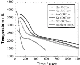
Figure 9shows the cooling process of carbon materials in the initial 1msec, determined by using a high-speed video camera combined with a laser furnace apparatus, indicating that the car- Fig. 9.Time evolution of the internal temperature of carbon nanoparticles, prepared by the laser furnace tech-
nique with Ni/Co carbon composite rods.
bon species cools down more rapidly than Ar, Ne, or Kr. Additionally, the yield of C60or other fullererens is also influenced much on the pressure of the ambient gas. Figure 10summarizes the yields of fullerene species (C60and C70) and SWNTs from the soot prepared by laser furnace tech- nique with Ni/Co carbon composite rods. It is interesting top point out that, only C60 or other fullerene species are prepared under lower pressure, even when using metal-carbon composite rods as starting materials.
Fig. 11.(left) Soot prepared with Ni/Co (0.6/0.6atom%) carbon composite rod by arc-burning technique under 50torr N2atmosphere; (right) Soot prepared with the same experimental condition under 1000torr N2atmosphere.
Fig. 10.Summary of the yield of fullerenrs (C60and C70) and SWNTs as a function of the pressure of ambient gas (N2and Ar) by using a laser furnace apparatus.
These experimental findings suggest the proper way of improvement of the preparation of SWNTs, e.g., in the arc burning process may exists. It was recently confirmed that the yield of the SWNTs increases when nitrogen gas is used as a buffer gas in the arc burning process with Ni/Co carbon composite rod, which was the same atomic ratio as that used in the laser furnace study [35]. Furthermore, one can clearly see that the yield drastically changes in the morphology as the pressure of nitrogen changes from 50torr to 1000torr (see Figure 11for the two extreme cases, the left shows the raw soot is found to be like a film, while the right looks like powder, which does not contain SWNTs. These differences come from the differences in the cooling behaviors. In the arc burning apparatus, the ambient temperature cannot be uniform between the center position of arc burning and the position of inner-wall of the apparatus, which is usually cooled down by water flow. Therefore, at the moment, it is found that the yield of SWNTs by arc- burning technique can reach only ca. 1/4compared with that obtained by laser furnace technique.
It is promising that controlling the internal temperature of precursors for the formation of SWNTs will give higher efficiencies, even in the case of arc burning technique.
Based on the consideration described above, the effort for the preparation of SWNTs having unique chirality is now going on, particularly using laser furnace technique. Recent experimental results indicates that it may be possible to get semi-conductive SWNTs having narrower and thin- ner diameter distribution than before, when the proper combination of metal catalyst and ambient gas is used for the preparation of them [36].
Acknowledgements
I would like to thank Prof. Dr. Wolfgang Krätschmer, Dr. Hiromichi Kataura, and Prof. Yohji Achiba for the comments and continuous encouragements during the course of the study, espe- cially that by using a high-speed video camera combined with a laser furnace technique. Also, I appreciate very much Dr. Tomonari Wakabayashi, Dr. Rahul Sen, Dr. Toshinobu Ishigaki, and Mr. Hirofumi Yamaguchi for their collaborations. Part of this work was supported by the funds of the Japan Society for the Promotion of the Science (JSPS) (“Future Program”), Industrial Technology Research Grant Program from New Energy and Industrial Technology Development Organization (NEDO) of Japan, Ishikawa Carbon Science Foundation, Nippon Sheet Glass Foundation for Materials Science and Engineering (NSG Foundation) and the Ministry of Education, Culture, Sports, Science and Technology (MEXT).
References
[1] M. S. Dresslhaus, G. Dresselhaus, and P. C. Eklund, Science of Fullerenes and Carbon Nanotubes (Academic Press, 1996).
[2] R. Saito, G. Dresselhause, and M. S. Dresselhaus, Physical Properties of Crabon Nanotubes(Imperial College Press, 1998).
[3] M. S. Dresselhaus, G. Dresselhaus, Ph. Avouris (Eds.), Carbon Nanotubes; Synthesis, Structure, Properties, and Applications(Springer, 2001).
[4] S. Iijima, Nature, 354, 56(1991).
[5] Y. Saito, Y. Tani, and A. Kasuya, J. Phys. Chem. B, 104, 2495(2000).
[6] Y. Chai, T. Guo, C. M. Jin, R. E. Haufler, L. P. F. Chibante, J. Fure, L. H. Wang, J. M. Alford, and R. E.
Smalley, J. Phys. Chem., 95, 7564(1991).
[7] A. Thess, R. Lee, P. Nikolaev, H. Dai, P. Petit, J. Robert, C. Xu, Y. H. Lee, S. G. Kim, A. G. Linzler, [9] J. Kong, A. M. Cassell, C. F. Quate, and H. Dai, Nature, 395, 878(1998).
[9] A. Cassel, J. Raymakers, J. Kong, and H. Dai, J. Phys. Chem., 103, 6484(1999).
[10] H. Dai, J. Kong, C. Zhou, N. Franklin, T. Tombler, A. Cassell, S. Fan, and M. Chapline, J. Phys. Chem., 103, 11246(1999).
[11] S. Maruyama, R. Kojima, Y. Miyaushi, S. Chiashi, and M. Kohno, Chem. Phys. Lett., 360, 229(2002).
[12] Y. Miyauchi, S. Yamakita, T. Okubo, and S. Maruyama, Chem. Phys. Lett., 375, 393(2003).
[13] Y. Murakami, Y. Miyauchi, S. Chiashi, and S. Maruyama, Chem. Phys. Lett., 377, 49(2003).
[14] K. Hata, D. N. Futaba, K. Mizuno, T. Namai, M. Yumura, and S. Iijima, Science, 306,1362(2004).
[15] Y. Aoki, S. Suzuki, S. Okubo, H. Kataura, H. Nagasawa, and Y. Achiba, Chem. Lett., 34, 562(2005).
[16] H. Tanaka, T. Yazawa, K. Eguchi, H. Nagasawa, N. Matsuda, and T. Einishi, J. Non-Cryst. Solids, 65, 301 (1984).
[17] S. Reich, C. Thomsen, and J. Maultzsch, Carbon Nanotubes; Basic Concepts and Physical Properties, 141- 149(Wiley-VCH, 2004).
[18] D. Nishide, H. Kataura, S. Suzuki, S. Okubo, and Y. Achiba, Chem. Phys. Lett., 392, 309(2004).
[19] M. J. O’Connell, S. M. Bachilo, C. B. Huffman, V. C. Moore, M. S. Strano, E. H. Haroz, K. L. Rialon, P. J.
Boul, W. H. Noon, C. Kittrell, J. Ma, R. H. Hauge, R. B. Weisman, and R. E. Smalley, Science, 297, 593 (2002).
[20] S. M. Bachilo, M. S. Strano, C. Kittrel, R. H. Hauge, R. E. Smalley, and R. B. Weisman, Science, 298, 2361 (2002).
[21] S. Lebedkin, K. Arnold, F. Hennrich, R. Krupke, B. Renker, and M. M. Kappes, New J. Phys., 5, 140.1 (2003).
[22] R. B. Weisman and S. M. Bachilo, Nano Lett., 3, 1235(2003).
[23] Y. Miyauchi, S. Chiashi, Y. Murakami, Y. Hayashida, and S. Maruyama, Chem. Phys. Lett., 387, 198 (2004).
[24] G. G. Tibbetts, J. Cryst. Growth, 66, 632(1984).
[25] H. Dai, A. G. Rinzler, P. Nikolaev, A. Thess, D. T. Colbert, and R. E. Smalley, Chem. Phys. Lett., 260, 471
(1996).
[26] S. Helveg, C. López-Cartes, J. Sehested, P. L. Hansen, B. S. Clausen, J. R. Rostrup-Nielsen, F. Abild- Pedersen, and J. K. Nørskov, Nature, 427, 426(2004).
[27] T. Saito, S. Ohshima, W.-C. Xu, H. Ago, M. Yumura, and S. Iijima, J. Phys. Chem. B., 109, 10647(2005).
[28] M. Yudasaka, R. Yamada, N. Sensui, T. Wilkins, T. Ichihashi, and S. Iijima, J. Phys. Chem. B, 103, 6224 (1999).
[29] R. Sen, S. Suzuki, H. Kataura, and Y. Achiba, Chem. Phys. Lett., 349, 383(2001).
[30] S. Iijima, T. Wakabayashi, and Y. Achiba, J. Phys. Chem., 100, 5839(1996).
[31] S. Suzuki, R. Sen, T. Tamaki, H. Kataura, and Y. Achiba, Eur. Phys. J. D, 24, 401(2003).
[32] unpublished result.
[33] F. Kokai et al., K. Takahashi, N. Yudasaka, and S. Iijima, J. Phys. Chem. B, 104, 6777(2000).
[34] D. Nishide, H. Kataura, S. Suzuki, K. Tsukagoshi, Y. Aoyagi, and Y. Achiba, Chem. Phys. Lett., 372, 45 (2003).
[35] Y. Makita, S. Suzuki, H. Kataura, and Y. Achiba, Eur. Phys. J. D, 34, 287(2005).
[36] S. Suzuki, N. Asai, H. Kataura, and Y. Achiba, Eur. Phys. J. D, 43, 143-146(2007).
![Fig. 3. TEM image of the soot prepared by laser-CVD method under 950 °C atmosphere [ 18 ].](https://thumb-ap.123doks.com/thumbv2/123deta/6868665.2247426/5.774.178.588.443.720/fig-tem-image-soot-prepared-laser-method-atmosphere.webp)
![Fig. 7. Time and spatial evolution of emission by the plume of carbon and metal nanoparticles, immediately after laser irradiation of a graphite rod (each image covers an area of 50 mm x 24 mm) [ 31 ]](https://thumb-ap.123doks.com/thumbv2/123deta/6868665.2247426/8.774.181.575.521.906/spatial-evolution-emission-carbon-nanoparticles-immediately-irradiation-graphite.webp)
![Fig. 8. Typical SEM images of soot produced in 1000 torr (a) N 2 , (b) Ar, (c) Ne and (d) Kr gases [ 34 ].](https://thumb-ap.123doks.com/thumbv2/123deta/6868665.2247426/9.774.155.614.559.949/fig-typical-sem-images-soot-produced-torr-gases.webp)