学位論文 博士(工学)
人間の振動特性と
車速による車両ダイナミクスの変化を考慮した 自動車用サスペンションの制御系設計
2011年 3月
慶應義塾大学大学院理工学研究科
鈴木 卓馬
自動車の乗心地向上,さらには操縦安定性のため,これまでに多くの制御デバイスと 制御手法が提案され,実用化されてきた.近年では,更なる性能向上のために,人間の 振動特性に関する研究や,路面外乱に対する車両挙動解析などの基礎研究も盛んに行わ れている.
本論文では,人間の振動特性と,車速による車両ダイナミクスの変化を考慮した自動 車用サスペンションの制御系設計法を確立することを目的とする.人間の振動特性とは,
乗員が着座姿勢において着座位置の振動に対する乗員挙動のダイナミクスを示す.また,
車速による車両ダイナミクスの変化とは,車両が走行する際に路面の凹凸によって生じ る車両挙動のダイナミクスの車速依存特性を示す.はじめに,着座姿勢の乗員挙動のダ イナミクスを考慮した乗員挙動制御の制御系設計を提案し,性能を検証する.次に,路 面の凹凸による車両ダイナミクスを考慮した制御系設計を提案し,性能を検証する.さ らに,路面の凹凸による車両ダイナミクスが車速によって変わることを考慮した制御系 設計を提案し,性能を検証する.
第1章では,本論文に関わる背景と目的を述べた.
第2章では,先行研究で明らかになっている人間の着座姿勢における着座位置の振動 に対する頭部の挙動データに基づき,乗員のダイナミクスをモデル化し,アクティブサ スペンションを備えた車両モデルと組み合わせ,H∞制御を適用して路面PSD (Power
Spectral Density) 特性を踏まえた外乱包含H∞制御系を設計する.数値シミュレーション
により,従来の制御系よりも乗員の振動を抑制する効果があることを示した.
第3章では,第2章で設計したアクティブサスペンションにおける制御系をセミアクテ ィブサスペンションに適用するため,車両と乗員の共振周波数といった代表的な周波数 において,サスペンション速度とセミアクティブダンパの減衰力のリサージュ波形に着 目し,速度がゼロ付近において減衰力の急激な変化を抑制し,ジャークを低減する制御 系を設計する.数値シミュレーションにより,従来の制御系よりも乗員の振動を抑制す る効果があることを示した.
第4章では,路面の凹凸によって発生するサスペンションのストロークおよびタイヤ 横力がタイヤ横力変化を生じさせることによるサスペンション特性を踏まえ,車両平面 運動も考慮した車両モデルに,車速を一定とした条件において,前後輪の路面入力の時 間差を導入し,前輪2輪から外乱が加わる車両モデルを構築する.本モデルにおいて,
アクティブサスペンションを用いて,乗心地のみならず,車両平面方向の挙動を制御量 とする外乱包含H∞制御系を設計する.数値シミュレーションにより,従来手法よりも,
路面凹凸に対する車両平面運動を抑制する効果があることを示した.
第5章では,第4章で構築した詳細なサスペンションおよび前後輪の路面入力時間差を 踏まえた車両モデルを車速に対するLPV (Linear Parameter Varying) 系で再定義し,アク ティブサスペンションを用いて,LMI (Linear Matrix Inequality) により車速によるゲイン スケジュール型H∞制御系を設計する.数値シミュレーションにより,提案手法を詳細 なサスペンション特性を踏まえて,ある車速で最適と設計した制御系と比較し,車速に よる車両ダイナミクスの変化に対するロバスト性を検証した.
最後に,第6章において,本論文の結論を述べた.
Automotive performance has improved from a demand for riding comfort and driving stability.
Many research have proposed various control system design methods for active and semi-active suspension systems. In recent year, research on dynamics of human body and vehicle dynamics are actively done. However, there are few research about a suspension control method considering those characteristics.
A purpose of this study is to establish a design method of control system considering dynamics of human body and vehicle dynamics at different vehicle speed for the vehicle suspension. The dynamics of human body means response of seated human due to vibration in seated position. The vehicle dynamics means vertical and lateral motion of the vehicle due to road input. First of all, to consider the dynamics of human body, seated position and vertical motion of the vehicle, “Passenger Control” is proposed. Second, the design method of control system which considers lateral motion of the vehicle due to change of tire side-force is proposed. In addition, the control system considers the characteristic of vehicle motions change depending on the vehicle speed is proposed. Those control performances are verified by some numerical simulations.
The contents of this dissertation are summarized as follows.
Chapter 1 describes the background and the purpose of this study.
In chapter 2, a vehicle and passenger model including the dynamics of human body at seated position is constructed. The disturbance accommodating H∞ control which considers both dynamics of human body and power spectral density of road disturbance is proposed. In order to verify the effectiveness of the proposed control system, the numerical simulations are carried out by using a full vehicle model. From numerical simulation, it was confirmed that in nearly the resonance frequency of a passenger’s head, the proposed control system is effective in reducing a passenger's vibration better than the general control system.
In chapter 3, the control system for the active suspension designed in Chapter 2 is applied to a semi active suspension. In order to control the jerk which is generated by changing of a damping coefficient rapidly, the robust controller is designed based on Lissajous figure of damping force. From numerical simulation, it was confirmed that the proposed control system reduces the jerk better than general control system.
In chapter 4, to consider suspension characteristic, which is change of tire side force caused by suspension stroke and tire side-force, a vehicle model including lateral motion is constructed. The disturbance accommodating H∞ control which considers the vehicle model, and sets the lateral acceleration of the vehicle to one of controlled outputs is proposed. From numerical simulation, it was confirmed that the proposed control system is effective for reducing the lateral motion of the vehicle due to antiphase road disturbance.
In chapter 5, the vehicle model in chapter 4 is defined as the linear parameter varying system taking amount of vehicle speed. The gain-scheduling controller based on the linear matrix inequalities which sets the vertical and lateral acceleration of the vehicle to one of controlled outputs is proposed. From the numerical simulation, the proposed gain-scheduling controller can reduce the vertical and lateral motions caused by road disturbance at a different vehicle speed better than a normal H∞ controller.
Chapter 6 is the conclusion of this dissertation.
目次
第1章 序論...1
1.1 背景... 1
1.1.1 サスペンション... 1
1.1.2 自動車における制御サスペンション... 2
1.1.3 研究事例... 4
1.1.3.1 制御サスペンションによる乗心地向上... 4
1.1.3.2 セミアクティブサスによる振動抑制... 5
1.1.3.3 制御サスペンションによる乗心地と操縦安定性の両立... 6
1.1.3.4 エネルギー回生... 6
1.1.3.5 人間の振動特性... 6
1.1.3.6 詳細なサスペンション特性を考慮した制御系設計... 7
1.1.3.7 車速による車両ダイナミクスの変化... 8
1.2 本論文の目的... 8
1.3 本論文の構成... 9
第2章 人間の振動特性を考慮したアクティブサスペンションによる制御系設計...12
2.1 緒言... 12
2.2 モデリング... 13
2.2.1 車両のモデル化... 13
2.2.2 乗員モデル... 15
2.2.3 車両-乗員モデル... 19
2.3 制御理論... 20
2.3.1 H∞制御... 20
2.3.1.1 H∞制御問題の定式化(161)(162)(163)... 20
2.3.1.2 標準H∞制御器の導出(161)~(165)... 22
2.3.1.3 非標準H∞制御器の導出(163)... 24
2.3.2 外乱包含制御... 25
2.3.3 外乱包含H∞制御... 26
2.4 制御系設計... 28
2.4.1 外乱包含H∞制御を用いた制御系設計... 28
2.4.2 上下加速度重みの設定... 30
2.5 数値シミュレーション... 31
2.5.1 計算条件と走行条件... 31
2.5.3 乗員のダイナミクスが異なる場合の応答... 38
2.6 結言... 41
第3章 減衰力のリサージュ図形に着目したセミアクティブサスペンションによる 制御系設計...42
3.1 緒言... 42
3.2 制御系設計... 44
3.2.1 外乱包含H∞制御の適用... 44
3.2.2 周波数重みの設定... 46
3.2.3 上下加速度重みに対する応答の比較... 46
3.3. 数値シミュレーション... 52
3.3.1 ランダム路面での従来手法との比較... 52
3.3.2 フルアクティブの乗員挙動制御との比較... 54
3.4 結言... 57
第4章 路面入力に対する車両の平面運動を考慮したアクティブサスペンションの 制御系設計...58
4.1. 緒言... 58
4.2 モデリング... 60
4.2.1 サスペンション特性を踏まえた車両モデル... 60
4.2.2 路面ロール入力による車両応答... 65
4.3 制御系設計... 66
4.3.1 路面に対する後輪への路面入力むだ時間の近似... 66
4.3.2 外乱包含H∞制御を用いた制御系設計... 68
4.3.3 周波数重みの設定... 70
4.4 数値シミュレーション... 73
4.4.1 計算条件と走行条件... 73
4.4.2 単一周波数路面での応答... 73
4.4.3 左右輪の路面が同位相のランダム路面... 75
4.4.4 左右輪の路面が逆位相のランダム路面... 75
4.5 結言... 76
第5章 車速による車両ダイナミクスの変化を考慮したアクティブサスペンション の制御系設計...77
5.1 緒言... 77
5.2 制御理論... 79
5.2.1 線形パラメータ変動系... 79
5.2.2 ゲインスケジュールドH∞制御(187)(188)... 79
5.3 制御系設計... 83
5.3.1 前輪への路面外乱に対する後輪へ入力のむだ時間の近似... 83
5.3.2 車速をパラメータとするゲインスケジュールドH∞制御の設計... 83
5.3.3 周波数重みの検討... 86
5.4 数値シミュレーション... 91
5.4.1 数値計算条件および走行条件... 91
5.4.2 単一周波数での応答... 92
5.4.3 ランダム路での応答... 92
5.5 結言... 99
第6章 結論...100
謝辞...103
参考文献...104
付録... 111
付録A 各モデルの詳細...111
A.1 車両モデル...111
A.2 乗員モデル...112
A.3 車両-乗員モデル...113
A.4 タイヤ横力発生モデルを含む車両モデル...113
付録B 複素コーナリングパワーの導出...114
著者論文目録...115
Fig. 1.1 Suspension(4)... 2
Fig. 1.2 Classification of ride comfort(6)... 2
Fig. 1.3 Classification of controlled suspension... 3
Fig. 1.4 Controlled suspension device ... 3
Fig. 1.5 Frequency response from road displacement to vertical acceleration of vehicle body... 5
Fig. 1.6 The content of Ph. D. dissertation... 10
Fig. 2.1 Vehicle model ... 14
Fig. 2.2 Passenger model ... 16
Fig. 2.3 Transfer function from seat to head (Translational motion, dot: Experiment(86), Line: Model). 18 Fig. 2.4 Transfer function from seat to head (Rotational motion, dot: Experiment(85), Line: Model)... 18
Fig. 2.5 Vehicle-passenger model ... 19
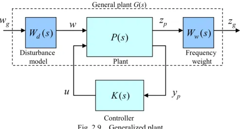
Fig. 2.6 Generalized Plant ... 21
Fig. 2.7 H∞ norm of Gzw(s) ... 21
Fig. 2.8 PSD of road surface(193)... 26
Fig. 2.9 Generalized plant ... 27
Fig. 2.10 Generalized plant for “Passenger Control”... 29
Fig. 2.11 Frequency weights for controlled value... 29
Fig. 2.12 Sensitivity curve of vertical vibration (ISO-2631)(111)... 29
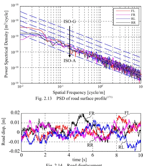
Fig. 2.13 PSD of road surface profile(171)... 32
Fig. 2.14 Road displacement ... 32
Fig. 2.15 Lissajous figure (Lateral and vertical acceleration) ... 34
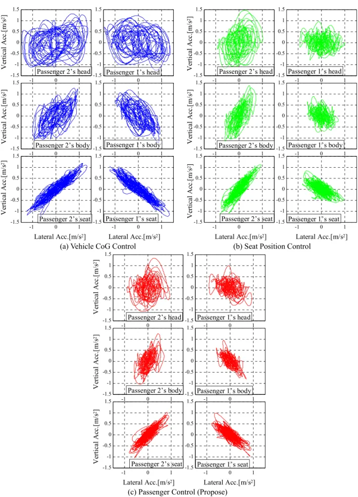
Fig. 2.16 Vehicle and passenger’s behavior (Vertical acceleration, unit:m/s2)... 35
Fig. 2.17 Actuating force... 35
Fig. 2.18 Power spectral density ... 36
Fig. 2.19 RMS value of vertical acceleration... 37
Fig. 2.20 Resonance frequency of head due to vertical vibration (15 subjects)(192)... 39
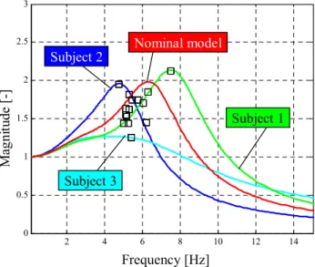
Fig. 2.21 Frequency response from seat to the head ... 39
Fig. 2.22 PSD of vertical acceleration (Passenger 1’s head)... 40
Fig. 2.23 RMS value of vertical acceleration of passenger 1’s head... 40
Fig. 3.1 Lissajous figure of control input at a single frequency ... 43
Fig. 3.2 Vehicle model ... 44
Fig. 3.3 Control system of semi-active suspension ... 45
Fig. 3.4 Semi-active dumper model ... 45
Fig. 3.5 Peak to peak value of the vertical acceleration and the vertical jerk ... 48
Fig. 3.6 Lissajous figure of suspension velocity and damping force of of “Vehicle CoG Control” ... 49
Fig. 3.7 Lissajous figure of suspension velocity and damping force of “Seat Position Control” ... 50
Fig. 3.8 Lissajous figure of suspension velocity and damping force of “Passenger Control” ... 51
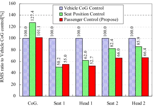
Fig. 3.9 Sum of peak to peak value of the vertical acceleration of passenger1’s head ... 52
Fig. 3.10 PSD value of vertical acceleration... 53
Fig. 3.11 Time history of passenger 1’s seat jerk ... 53
Fig. 3.12 Time history of passenger 1’s head jerk... 54
Fig. 3.13 RMS value of vertical acceleration and actuating force ... 55
Fig. 3.14 PSD value of vertical acceleration... 56
Fig. 4.1 Toe change and scuff caused by roll motion... 59
Fig. 4.2 Toe change and scuff caused by tire side force... 59
Fig. 4.3 Vehicle model ... 61
Fig. 4.4 Tire motion caused by bounce motion ... 62
Fig. 4.5 Imaginary link of suspension ... 62
Fig. 4.6 Tire motion caused by tire side force... 63
Fig. 4.7 Vehicle response caused by antiphase road disturbance ... 65
Fig. 4.8 Approximation of time delay of road disturbances from front to rear wheels... 67
Fig. 4.9 Vehicle response of vehicle model which includes the Pade approximation... 67
Fig. 4.10 Generalized plant ... 69
Fig. 4.11 Frequency weight... 69
Fig. 4.12 Lateral acceleration (Rear view) ... 69
Fig. 4.13 Sensitivity curve of lateral vibration (ISO-2631)(111)... 70
Fig. 4.14 PSD of road surface profile(171)... 71
Fig. 4.15 Road displacement ... 72
Fig. 4.16 RMS value changed by evaluation function of lateral acceleration... 72
Fig. 4.17 Road displacement (Case 1)... 73
Fig. 4.18 Time history of vertical and lateral acceleration (Case 1) ... 74
Fig. 4.19 Time history of lateral acceleration (Case 1) ... 74
Fig. 4.20 PSD of Vertical acceleration (Case 2)... 75
Fig. 4.21 PSD of Lateral acceleration (Case 3)... 75
Fig. 5.1 Contour diagram of vehicle motion due to road input (Gain characteristic of transfer function) ... 78
Fig. 5.2 Gain-schedule control system ... 81
Fig. 5.3 Approximation of time delay of road disturbances from front to rear wheels... 83
Fig. 5.4 Generalized plant of proposed method ... 85
Fig. 5.5 Frequency weights Wi(s) ... 85
Fig. 5.6 Sensitivity curve of vibration (ISO-2631)(111)... 86
Fig. 5.7 PSD of road surface profile(171)... 87
Fig. 5.8 Road displacement of front-left wheel... 88
Fig. 5.9 Contour diagram of RMS value of accelerations (V = 20 km/h, unit : m/s2) ... 88
Fig. 5.10 Contour diagram of RMS value of accelerations (V = 70 km/h, unit : m/s2) ... 89
Fig. 5.11 Contour diagram of RMS value of accelerations (V = 120 km/h, unit : m/s2) ... 89
Fig. 5.12 Frequency weight of Kw1 and Kw2... 90
Fig. 5.13 Gain diagram of LTI vertex controllers (Front-left speed to front-left actuating force) ... 90
Fig. 5.14 Time history of road case 1 (Vehicle response, V= 70 km/h) ... 93
Fig. 5.15 Time history of road case 1 (Vehicle response, V= 120 km/h) ... 94
Fig. 5.16 Actuating force of road case 1 (V=70 km/h)... 95
Fig. 5.17 PSD of acceleration (V = 70 km/h) ... 96
Fig. 5.18 PSD of acceleration (V = 120 km/h) ... 97
Fig. 5.19 RMS of acceleration (Each speed and sum of 3 conditions) ... 98
Table 2.1 Specification of vehicle model ... 14
Table 2.2 Earlier study of seated human model(85)(89)(95)... 16
Table 2.3 Specification of passenger model... 19
Table 2.4 Controlled value of each method... 31
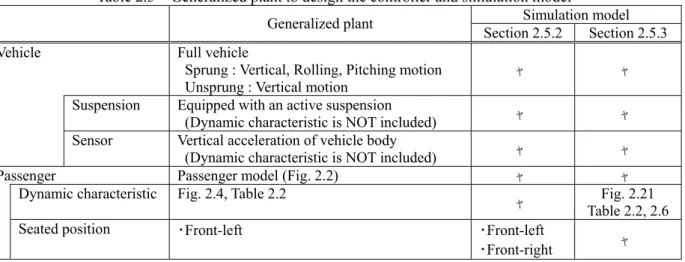
Table 2.5 Generalized plant to design the controller and simulation model ... 31
Table 3.1 Generalized plant to design the controller and simulation model ... 45
Table 3.2 Road displacement ... 47
Table 3.3 Controlled value of each method... 47
Table 3.4 Specifications of each method... 55
Table 4.1 Modeling of suspension characteristics... 61
Table 4.2 Specification of suspension characteristics ... 65
Table 4.3 Controlled value of each method... 71
Table 4.4 Generalized plant to design the controller and simulation model ... 71
Table 4.5 Driving condition ... 73
Table 5.1 Controller... 91
Table 5.2 Generalized plant to design the controller and simulation model ... 91
Table 5.3 Driving condition ... 91
Symbol Definition Units Symbol Definition Units Mb
Mass of sprung
(Vehicle body) kg mb Mass of passenger’s head kg
Mt
Mass of unsprung
(Tire and wheel) kg mh Mass of passenger’s body kg
Ir
Moment of Inertia of
vehicle rolling kg m2 Ihr Moment of Inertia of
passenger’s head (Rolling) kg m2 Ip
Moment of Inertia of
vehicle pitching kgm2 Ihp Moment of Inertia of
passenger’s head (Pitching) kg m2 Iy
Moment of Inertia of
vehicle yawing kgm2 kpi (i = 1, 3, 4, 6) Each stiffness in passenger
model (Fig. 2.2) N/m
Kf,r
Stiffness of Suspension
(Front, Rear) N/m cpi (i = 1, 3, 4, 6) Each damping in passenger
model (Fig. 2.2) N/m/s
Cf,r
Damping of Suspension
(Front, Rear) N/m/s kpi (i = 2, 5) Each stiffness in passenger
model (Fig. 2.2) Nm/rad
Tf,r Tread (Front, Rear) m cpi (i = 2, 5) Each damping in passenger
model (Fig. 2.2) Nm/rad/s g Acceleration of gravity m2/s ri(i = 1,・・・, 5) Each distance in passenger
model (Fig. 2.2) m
Hr Rolling moment arm m xpi (i = 1, 2) Longitudinal displacement of seated position (Passenger 1, 2)
m
Hp Pitching moment arm m ypi (i = 1, 2) Lateral displacement of seated position (Passenger 1, 2)
m
Lf,r
Distance from to CoG. of vehicle to each axis (Front, Rear)
m zpi (i = 1, 2) Vertical displacement of seated position (Passenger 1, 2)
m
L Wheelbase m xbi (i = 1, 2) Longitudinal displacement
of passenger’s body (Passenger 1, 2)
m
Fi (i = 1,…, 4) Actuating force of active
suspension (Each wheel) N ybi (i = 1, 2) Lateral displacement of passenger’s body (Passenger 1, 2)
m
Fdi (i = 1,…, 4)
Damping force of semi-active suspension (Each wheel)
N zbi (i = 1, 2) Vertical displacement of passenger’s body (Passenger 1, 2)
m
Fli (i = 1,…, 4) Actuator force command
(Each wheel, Fig. 3.3) N xhi (i = 1, 2) Longitudinal displacement of passenger’s head (Passenger 1, 2)
m
f Body roll angle rad yhi (i = 1, 2) Lateral displacement
of passenger’s head (Passenger 1, 2)
m
q Body yaw angle rad zhi (i = 1, 2) Vertical displacement
of passenger’s head (Passenger 1, 2)
m
zri(i = 1,…, 4) Vertical displacement of
road (Each wheel) m fhi (i=1,2)
Roll angle
of passenger’s head (Passenger 1, 2)
rad
Symbol Definition Units Symbol Definition Units zui(i = 1,…, 4) Vertical displacement of
unsprung (Each wheel) m qhi (i=1,2)
Pitch angle of passenger’s head (Passenger 1, 2)
rad
zsi (i = 1,…, 4) Suspension stroke
(Each wheel) m ai (i=1,2) Tire slip angle
(Each tire, Appendix B) rad zti (i = 1,…, 4) Tire deformation
(Each wheel) m b Slip angle (Vehicle) rad
pxi (i = 1,…, 4) Distance from to CoG. of vehicle to each seat position (Longitudinal direction)
m g Yaw rate (Vehicle) rad/s
pyi(i = 1,…, 4) Distance from to CoG. of vehicle to each seat position (Lateral direction)
m V Vehicle speed m/s
pzi(i = 1,…, 4) Distance from to CoG. of vehicle to each seat position (Vertical direction)
m KCf,r Cornering stiffness
(Front, Rear) N/rad
Fyi(i = 1,…, 4) Tire side force
(Each wheel) N Ksf,r Stroke steer coefficient
(Front,Rear) rad/m
hcg Height of CoG. of
vehicle body m KSFf,r Compliance steer coefficient
(Front, Rear) rad/N
hrf,r Height of roll center
(Front, Rear) m KPFf,r Lateral suspension stiffness
(Front, Rear) m/N
yCG
&& Lateral acceleration of CoG.
of vehicle body m/s2 t Time lag of front to
rear wheel s
yRC
&& Lateral acceleration of roll
center of vehicle body m/s2
第 1 章 序論
1.1 背景
1.1.1 サスペンション
自動車が発明され,量産が始まってから既に100年以上もの年月が経過し,生産台数はやや減少 傾向にあるものの(1),自動車の総台数は今もなお増え続けている現状にある(2).自動車は,ユーザー からのニーズに応え,様々な技術革新・開発が行われてきた.自動車のサスペンションは,乗心地 性能以外にも,操縦安定性,振動・騒音性能などを左右する自動車を支える重要な部品(システム)
であり,他性能とのトレードオフを克服しながら,幅広いユーザーのニーズに応えてきた.
近年では環境問題に対する意識が強まりつつある中,燃費性能に優れるハイブリッド車や電気自 動車などに注目が集まっている.それら自動車は,電気モータにより駆動をする自動車であり,化 石燃料を駆動エネルギーに変える内燃機関を備える車両に比べ,駆動源からの騒音が小さく静粛性 に優れる特徴がある.そのため,「静かな車」は,車外の人にとって認知しづらくなり危険を感じ る車両になりかねないという報告がある(3).一方,乗員にとってはこれまで内燃機関などから発生 する振動や騒音によって白色ノイズとして埋もれていたものが特徴的な振動や騒音として表れる 現象がある.そのため,今後は,振動や騒音といった快適性・静粛性に関するニーズ,さらには心 地よいサウンドや乗心地など,より高いレベルのニーズを実現する必要がある.
サスペンションとは,タイヤと車体の間に設けられた懸架装置であり,量産されている自動車の すべてに備えられ,車両レイアウトや車両性能に合わせ様々な形式が実用化されている.図1.1に示 すのは前輪および後輪の代表的なサスペンション(4)のひとつであり,ばね・ダンパといった振動吸 収部品だけでなく,タイヤと車体を連結するサスペンションアームなどから構成される.サスペン ションには振動吸収機能以外にも,車体姿勢制御機能,タイヤ姿勢制御機能がある.振動吸収とは,
路面の凹凸によって車両が振動するのを抑制する機能であり,車体姿勢制御機能とは,車体の重量 を支え,旋回時や制駆動時の車体の姿勢変化を抑制する機能である.また,タイヤ姿勢制御機能に より,車輪は操舵や車輪自身の上下方向の動き,走行中の外力などにより車体に対してタイヤの向 きをコントロールすることでタイヤの性能を適切に発揮し,タイヤが発生する力を車体に伝えるこ とができる.それらサスペンションの機能を発揮するためにばね・ダンパの仕様やサスペンション のジオメトリ,各サスペンションアームを連結するブッシュの仕様などが詳細に検討され,乗心地 と操縦安定性,さらには振動・騒音性能のトレードオフを克服しながら,車両としてそれら性能を 実現している.
乗心地性能の現象について,簡単に分類したのが図1.2である.周波数が高くなるに従い,フワフ ワ,ヒョコヒョコ,ブルブル,ゴツゴツ・ビリビリ振動(5)といわれ,低周波域の振幅が大きい領域
(a) Front suspension (b) Rear suspension Fig. 1.1 Suspension(4)
Frequency [Hz]
1 10 100
Amplitude SmallLarge
Handling-stability
Noise & Vibration
“Huwa-Huwa”
vibration
“Hyoko-Hyoko”
vibration “Buru-Buru”
vibration “Gotsu-Gotsu”
“Biri-Biri”
vibration Impact harshness Dumping after
harshness
Fig. 1.2 Classification of ride comfort(6)
では操縦安定性と重なり,高周波の振幅が小さい領域では騒音・振動性能が伴う現象と重なってお り,一般的に乗心地性能とそれらはトレードオフの関係にある.例えば,一般的に乗心地性能から はダンパの減衰力を下げたく,操縦安定性からは減衰力を高めたいという相反する設計要求が生じ る.このような課題は一例であり,様々なトレードオフを克服するために,メカニカルなサスペン ション構造によって克服する方法や,制御サスペンションによって克服するなど様々な方法が提案 され,多くが実用化されてきた(12)(13)(14)(17)(18)(29)(30)(44)(45)(46)(194)(195).
1.1.2 自動車における制御サスペンション
乗心地性能,操縦安定性さらに騒音・振動性能のトレードオフを克服し,それら性能を高めるこ とができるサスペンションに制御サスペンションがある.図1.3に制御サスペンションの分類を示す.
制御サスペンションには,懸架装置自らが力を発生しタイヤ(ばね下)と車体(ばね上)間の相対 変位を自在に変更することができるアクティブサスペンション(以後,アクティブサス),懸架装 置のダンパの減衰力を自在に変更することができるセミアクティブサスペンション(以後,セミア
Controlled suspension Active susp.
Semi-active susp.
Hydraulic Pneumatic
Electrical-motor Rotary type Liner type
Active stabilizer
Hydraulic
Magnetic-Rheological fluid Electro-Rheological fluid
Hydraulic Electrical-motor Kinetic susp.
Adjustable geometry susp.
Fig. 1.3 Classification of controlled suspension
Linear motor
Comfort mode Sport mode
Solenoid coil headed Solenoid coil not
headed Piston drillings
Particle
(a) Active suspension
(Electrical motor type, Bose K. K.)(11)
(b) Semi-active suspension
(Magnetic-Rheological fluid type, Audi AG.)(12) Fig. 1.4 Controlled suspension device
クティブサス),左右輪の懸架装置の相対変位差に作用するスタビライザの剛性を自在に変更でき るアクティブスタビライザ(以後,アクティブスタビ),懸架装置のダンパの油圧回路を連結し,
各輪のサスペンションの動きに拘束力を作用させる連結式サスペンション (Kinetic suspension)(7)(8), さらにはサスペンションのリンク取り付け位置を自在に変えるジオメトリ可変サスペンション (Adjustable geometry suspension)(9)(10)などがある.そのうち,アクティブサス,セミアクティブサス,
アクティブスタビは,更に細かく分類ができる.アクティブサスは,1950年代から開発が始まり(194),
1980年代初めに車高を調整するシステムが生産車に適用され(195),これまでに油圧式,空圧式,電気
モータ式が提案されている.近年は,油圧式に比べ高応答な図1.4(a)に示す電気モータを利用したア クティブサスのシステムがいくつか提案されている(11)(14)(15)(28)(64)(66)~(74)(196).一方,実用化の観点からは アクティブサスに比べ,セミアクティブサスの方が多く採用され,油圧のダンパの減衰力を調整す
る形式(194)(195),ダンパに電気粘性流体(ER流体:Electrorheological-Reological Fluid)を用いたり,図
1.4(b)に示すような磁性流体(MR流体:Magnetrical-Reological Fluid)を用いた形式(12)が提案,実用
化されている.さらに,アクティブスタビは,油圧によって剛性を変更する形式(13)や,電気モータ によって剛性を変更するタイプ(14)などが実用化されるなど,近年,様々な形式が提案され(15),実用 化されている.
以上のような,制御サスペンション装置を用いて,様々な要求に対応する制御手法がこれまでに 提案されてきた.次節では,上記の制御装置を用いた制御手法に関する過去の研究事例を述べる.
1.1.3 研究事例
1.1.3.1 制御サスペンションによる乗心地向上
サスペンションの制御として最も広く知られているのが,スカイフック制御である.図1.5に示す のは一輪の車両モデルにおいて,路面入力に対するばね上の加速度の周波数応答であり,図1.5(a) はコンベンショナルなサスペンションにおいてメカニカルなダンパを強くした場合の応答,図 1.5(b)はフルアクティブサスで理想的なスカイフック制御を実現した場合の応答である.メカダン パを強くした場合,ばね上およびばね下の共振周波数域の振動を抑制する効果があるが,ブルブル 振動といわれる5Hz 前後の振動は悪化する問題があるのに対して,理想的なスカイフック制御は,
ブルブル振動の増加を生じず,ばね上の共振周波数帯域の振動を抑制する効果があることが知られ ており,赤津はばね上共振での路面に対するばね上の振動伝達比は,スカイフックダンパの減衰比 を適切に設定すれば,1以下になることを示している(16).1980年代に空圧アクティブサス(エアサ ス)を用いてスカイフック制御が適用され(17),1980年代終わりには油圧アクティブサス(油圧アク ティブ)により実現されている(18).
また,車体の振動に対してフィードバックを行うスカイフック制御に対して,車輪が通過する路 面情報をフィードフォワードするプレビュー制御がある.プレビュー制御は,大きく2つに分類さ れ,車両が通過する前の路面情報を用いる方式と,前輪が通過した路面情報を後輪のアクティブサ スが用いる方式がある.
川越らは一輪モデルにおいては前者,ハーフビークルモデルにおいては後者の方式を用いて,最 適プレビュー制御を解析的に導き,プレビュー制御の効果を出すには最低限0.1秒先のプレビューが 必要であると結果を示し(19),藤岡らは有限時間の最適制御問題にあてはめ,制御器を導出し,プレ ビュー制御の効果は1.5秒で飽和する結果を示した(20).永井らは制御器の導出に H∞制御を適用し,
LQG制御でプレビュー制御を行った場合よりも良い結果を示し(21),Thompsonらも最適制御を基本 とした制御則をいくつも提案している(22)(23).
一方,前輪が通過した路面情報を後輪のアクティブサスが用いる方式においては,赤津らは前輪 のばね下の動きから路面の凹凸を推測し,後輪が通過するタイミングに路面からの伝達力を相殺す る予見制御を提案し,実車においてもその有効性を示している(16)(24).永井らが非線形ニューラルネ ットワークにより後輪の路面外乱を推定し,それを補償する手法(25)や,荒木らは予見最適アルゴリ ズム(26)を適用し,Zhangらは前後輪の路面入力むだ時間をPade近似し,それをモデルに考慮したカ ルマンフィルタを設計し,最適制御を適用した手法(27)を提案している.また,電動アクティブサス ペンションに適用し,乗心地向上と消費電力低減を実現した報告もある(28).実用化の観点からは,
路面と車体の相対変位から路面の粗さにより減衰力を切り替える方式(29)や,同様のセンシングによ り路面入力が作用する前に減衰力を切り替えて乗心地を向上させる方式(30)が実用化されているが,
より詳細に路面の凹凸をセンシングし制御に利用する手法は,路面情報のセンシングの難しさから,
まだ実用化されていないのが現状である.
100 101 0
10 20 30 40 50 60
70 ばね上加速度/路面変位
F[Hz]
Gain[db (m/sec2)/m]
100 101
0 10 20 30 40 50 60
70 ばね上加速度/路面変位
F[Hz]
Gain[db (m/sec2)/m]
1 10 1 10
Frequency [Hz] Frequency [Hz]
Gain [dB m/s2/m] 0204060 Gain [dB m/s2/m] 0204060
Damping coefficient
Damping coefficient (Skyhook dumper) Low
High
Low
High
(a) Conventional suspension (b) Skyhook control Fig. 1.5 Frequency response from road displacement to vertical acceleration of vehicle body
1.1.3.2 セミアクティブサスによる振動抑制
セミアクティブサスは,フルアクティブサスに比べ,消費するエネルギーが遥かに小さく,パッ シブサスペンションに比べ振動抑制が可能であること(197)から,セミアクティブサスを適用した車両 が多く開発,生産されてきた.しかし,セミアクティブサスは双線形システムであるため,アクテ ィブサスのような線形システムのようにサスペンション速度によらず,常に推力(減衰力)を発生 することが不可能である.そのため,サスペンション速度がゼロ付近では,急激な減衰力の変化が 生じ,ばね下の共振が抑えられず不安定なハンチング現象が発生したり,車体のジャークが大きく なったりするなど,セミアクティブサスを実車適用するための課題がある.
このような問題に対して,Karnopp らはスカイフック制御をセミクティブサスに適用し,近似ス カイフック制御則(31)を提案している.Miller らはばね上の加速度のみならずジャークの低減をも狙 った制御則(32)を提案し,永井らは減衰係数を連続的に切り替えオンオフ型の不安定性を緩和した連 続系制御則(33)を提案し,Yiらはスカイフック制御およびグランドフック制御のフィードバックゲイ ンをニューラルネットワークで設計する手法(34)を提案している.また,三平らは非線形 H∞制御を セミアクティブサスへ応用し,制御則を導き,線形 H∞制御を用いた場合に比べて制御効果が高い こと(35)を示し,実用化している(45)(46).吉田らは双線形H∞制御をフルビークルの車両モデルに適用し ている(36).横山らはモデル追従型制御理論に基づいたスライディングモード制御器(37)やニューラル ネットワークを用いて制御器(38)を設計し,西村らはセミアクティブダンパを線形パラメータ変動 (LPV: Linear Parameter Varying) 系でモデル化したゲインスケジューリング制御(39)(40),深尾らはセミ アクティブダンパの非線形性も考慮するためバックステッピング法を用いた制御則(41)をそれぞれ 提案している.さらに,Sergioらは近似スカイフック制御則に加えて,ばね上の上下加速度をフィ ードバックする制御を行うことでブルブル領域の振動低減を実現し(42),Stamatらはさらなるジャー ク低減を目指し,Karnopp らの近似スカイフック制御則に時間ベースの推力調整則を加えた手法(43) を提案するなど,多くの手法が提案されている(198)(199)(200).また,実車適用の観点からは,平井らが Karnoppらの手法を改良した制御則を商品化(44)したり,非線形H∞制御を採用した報告(45)(46)もあるが,
その制御則の多くは一輪の車両モデルを前提にした方式が多く,4輪の車両モデルを用いた制御系 設計を提案する例は数少ない.
1.1.3.3 制御サスペンションによる乗心地と操縦安定性の両立
乗心地と操縦安定性の両立に関しても研究開発が行われてきた.操舵に対する車両の運動性能の 向上として,ロール角制御(47),前後剛性配分制御(18)(48)(201)(202),ピッチ角制御(49)(50),が古くから提案さ れ,路面入力に対する各輪の輪荷重変化を低減し,車両の挙動を低減する接地荷重制御(51)(52)(53)など もある.また,ロールとピッチ角の位相差に関する実車実験から前下がりロールかつロールとピッ チの位相差をゼロに近づける方が,ロール感が良いという先行研究(54)(55)を元にロールとピッチの位 相を制御した手法もある(56).
制御サスペンショと他の制御システムの統合制御に関しては,ブレーキの協調制御により限界性 能を向上させた報告(57)や,ABS (Antilock Brake System) との統合制御により制動性能を向上させた 報告(58)や,ブレーキとの統合制御により緊急時にブレーキによるロールオーバーのリスクの回避を 狙った報告(59)や,ハンドリング性能を向上させた報告(60)や,車両横運動に連携して加速度を制御す るG-Vectoring制御(203)との統合制御を実現した報告(204)(205)もある.一方,操舵系とサスペンションの 制御に関しては,前輪操舵角のアクティブ制御との統合制御(61)(62)や,4WS (4 Wheel Steering) との制
御(194)(206)や,電動パワーステアリングとアクティブスタビライザとの統合制御(63)に関しても報告があ
る.
1.1.3.4 エネルギー回生
アクティブサスによる車両運動の制御以外に,路面不整による振動エネルギーを回生する研究も 行われている.岡田らは小型の直動モータを用いてシミュレーションと実機実験により,加えられ る振動の周波数が系の固有値よりも高ければ,アクティブな制振のために消費するエネルギーより も多くの振動エネルギーを回生できることを示し(64),則次らはセミアクティブダンパとアクティブ 要素であるエアサスペンションを併用し,スカイフック制御に周波数フィルタを加え,制振性能と 消費エネルギー低減を実現している(65).須田らはセルフパワード・アクティブ制御の実現に向けた 解析を行い(66),ボールねじ式の電磁サスペンションを開発し,実車実験を行い(67)ながら,最適な制 御ゲインの検討を行っている(68).福島らは変分法をベースとした最適制御問題の近似解法をしエネ ルギー回生機能を有するアクティブサス制御へ適用し(69),油圧システムを前提としたサスペンショ ンのHILS (Hardware In the Loop Simulation) を構築し,検証を進めている(70).一方,海外の研究チー ムでは,車両に搭載可能なサイズに近い大きさのリニアアクチュエータタイプの電磁アクティブサ スの磁場解析などを行い(71)(72)(73),実車への適用を前提にシミュレーションによる回生効果が報告さ れている(74).
1.1.3.5 人間の振動特性
人間の振動特性に関しては,古くから大変多くの基礎研究が行われており(75),自動車の乗心地の 測定方法や定量評価に用いられている(76)(77)(78).自動車の乗心地に関連した人間の振動に関する研究 は大きく4つに分類することができ,人間の振動特性(ダイナミクス)の実験解析,振動特性のモ デル化,そのモデルなどを用いた挙動評価,振動感受特性である.
人間の着座姿勢における振動特性は,Griffin ら(79)~(84)や,吉村ら(85)~(90)(98)(209)など多くの研究者が実 験により動特性が明らかにしており,人間自身に限らず,着座するシート(88),(91)や,ヘッドレストの 影響を踏まえた実験報告(92)もある.また,近年は,着座姿勢での脚部の影響を踏まえた報告(206)や,
着座姿勢ではなく倒立姿勢での上下方向(93)や前後方向(94)の振動特性に関する報告があるなど,人間 の振動特性は,様々な条件での実験結果が示されている.
そのような実験データをモデル化したものとしては,ばね-ダンパ-質量系のモデルがあり,
ISO-5982で規格化されたモデル(95)に代表される並進ばねにより体の一部を模擬した質量が連結され
たモデル(85)(88)(91)(97)や,回転ばねを多用し連結されたモデル(98)(99)(209)や,並進ばねと回転ばねを多用し
連結されたモデル(84)(96)(100)がある.また,マルチボディダイナミクスを用いたモデル(89)(209)や,FEMを 用いたモデル(82)(83)などが多く提案されている.
またそのようなモデルを用いて,コンベンショナルな車両において,乗員の挙動をシミュレーシ ョンした報告(101)もあり,特に西山は路面不整に対する乗員の挙動を様々な条件において数値シミュ レーションにより解析している(102)~(105).近年は,制御サスペンションによる振動抑制の効果を乗員 モデルの動きの少なさで評価した報告(106)(107)や,鉄道の分野において乗員の振動とシート特性を踏ま えてモデル化した報告(108)や,乗員質量と鉄道車両の弾性特性との連成を考慮した運動を実験と数値 シミュレーションの報告がある(109).一方,乗員のダイナミクスを踏まえて制御系設計を行っている のは,シート下に設けたセミアクティブダンパの制御に用いた報告(110)がある程度で,乗員のダイナ ミクスを制御系設計に直接考慮した制御系は少ない.
振動感受特性は,Janeway によって提案された上下振動許容限界(210)など,多くの研究者により実 験により明らかにされている(75).また,ISO-2631では規格化もされ(111),その妥当性も報告されてい
る(112).上下方向の振動に関しては,乗員の主観的な官能評価を客観的に評価できる乗心地評価式も
いくつか提案され(113)(114),長時間運転時の振動による疲労評価の報告(115)や,運転者と同乗者の振動 伝達特性と不快感の差を明らかにした報告(116)もある.一方,上下方向の振動以外では,ロールとピ ッチの複合振動感受特性を解析した報告(117)(118)や,バウンスとピッチ,バウンスとピッチ,ロールの 複合振動感受特性を解析した報告(119)(211)や,ヨー方向の運動知覚感度特性を解析した報告(120)(121),上 下および横方向の複合振動を解析した報告(122),低周波数の上下および前後の複合振動感受特性を解 析した報告(123)(124)などもある.また,低周波数領域での乗心地の定量化には,走行中の頭部や体幹部 といった乗員挙動の計測も重要と考えられ,操舵中のドライバ挙動を実車実験により明らかにした
報告(125)(126)や,車酔い定量化のための頭部動計測(127)や,乗心地を目的とした計測の報告(128)などもあ
る.固定式のドライビングシミュレータを用いて,路面の平坦性が乗心地と走行時安心感に与える 影響を検証した報告(129)や,舗装わだち掘れ路面を走行した際の乗心地評価を行っている報告(130)もあ る.近年では,動揺や視覚に対する人間の感受特性を踏まえた四輪アクティブステア制御の提案(212) もある.制御サスペンションにおいては,振動感受特性を考慮した制御系設計(56)(131)(132)や,前後方向 の着座位置を考慮した制御系設計(213)や,一輪モデルを用いて上下方向の乗員の振動特性(ダイナミ クス)を考慮した制御系設計(110)はあるが,フルビークルモデルを用いて車両の上下運動に加え,ロ ールおよびピッチ運動も考慮し,乗員の挙動を制御している研究報告はない.
1.1.3.6 詳細なサスペンション特性を考慮した制御系設計
サスペンションは,前節で述べたとおり,3つの機能を実現するために,複雑なリンク構造や非 線形なばね・ダンパ特性に設定されている(133)(134)(135).西村らは,セミアクティブダンパの可変減衰 力の非線形特性とばねの非線形特性を線形パラメータ変動系にモデル化したゲインスケジュール 型 H∞制御則を提案し,数値シミュレーションおよびMRダンパを用いた実機にて,高い制御性能 を示している(39)(40).西村らの研究報告以降,近年ではセミアクティブダンパを備えた一輪モデルを