Characteristics of flow patterns under pulsatile flow with same oscillatory fraction in the grooved channel
Yunjie YANG1, Yongning BIAN1*, Hirofumi ARIMA2 and Yasuyuki IKEGAMI2
1State Key Laboratory of Structural Analysis for Industrial Equipment Dalian University of Technology, 116024, China
2Institute of Ocean Energy, Saga University, 840-8502, Japan
Abstract
The characteristics of flow structure under pulsatile flow with same oscillatory fraction in the grooved channel are investigated experimentally. The flow patterns under pulsatile flow in the grooved channel are divided into 4kinds in this study. The effects of frequency, groove length and t/T on the flow patterns are analyzed. The results showed that the instability of the flow enhances with t/T during the deceleration phase. As the frequency increases, the onset of the unstable flow state is postponed, but the strongly unstable state (3) starts to appear and advance gradually. Moreover, the onset of the unstable state gradually advances as the increase of groove length.
Keywords: pulsatile flow; grooved channel; flow visualization; oscillatory fraction 1. Introduction
Development and utilization of marine energy is the key research direction with the problem of low energy and increasingly serious environmental pollution. As an environmentally friendly and sustainable new energy, ocean thermal energy conversion (OTEC) has attracted more and more attention. OTEC uses the temperature difference between the warm seawater at the surface and cold seawater at the depths. However, the thermal efficiency of the present OTEC is very low because of the finite temperature difference. Improving the heat transfer efficiency of exchanger is one way to improve the thermal efficiency of OTEC.
Bian et al. [1] conducted a series of the flow characteristics for pulsatile flow in grooved channels experimentally, the results showed that the local pressure and the overall pressure drop change significantly with the groove length. Zhang et al. [2] discover that the pressure drop decreases with the frequency of the pulsatile flow in the laminar flow and transitional flow for the same oscillatory fraction, while it has an inflection point and then increases in the turbulent flow. Huang et al. [3] studied pressure drop characteristics of laminar pulsatile flow in grooved channel with different groove lengths experimentally. Their results suggested that the relation between amplitude and frequency of pulsatile is the same to different grooved channel. Pan et al. [4] observed that the experimental oscillatory fraction of the flow rate is easier to reach the theoretical value at lower oscillatory frequency.
Zhang et al. [5] found that the oscillatory fraction decreases with frequency of pulsatile flow by the flow visualization results.
In this study, the characteristics of the pulsatile flow in the grooved channel are analyzed. The effects of t/T, frequency and groove length (l) on the flow patterns are examined.
* Received date: 2020.11.10
Email of the corresponding author: [email protected]
To get a better understanding of the pulsatile flow, some parameters are defined as follows:
The net flow Reynolds number (Re)
�� � 𝜌𝜌𝑢𝑢�/𝜇𝜇 (3) where 𝜌𝜌 and 𝜇𝜇 are the density and the viscosity of water respectively. The characteristic velocity[6] of the flow u is calculated by:
𝑢𝑢 �3/2∗ 𝑢𝑢� (4) where 𝑢𝑢� is calculated as follow
𝑢𝑢�� 𝑄𝑄�/�2��� (5) The oscillatory fraction (P) of the flow rate
� � 𝑄𝑄�/𝑄𝑄� (6) The instantaneous velocity 𝑢𝑢� is depicted as:
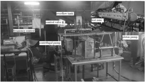
𝑢𝑢�� 𝑢𝑢�� � ∗ 𝑢𝑢�∗sin �2���� (7) The entire experimental setup is shown in Fig. 2. Fig. 3 shows a schematic of the experimental system. The city water is used as the working fluid and feed water is stored at the circulating tank. The flow is supplied to the test zone by a centrifugal pump and the flow rate is adjusted by the control valve. The piston pump driven by a servo motor through the Scotch-yoke mechanism to cover a range of pulsating flow parameters is used to obtain the imposed oscillatory flow. After passing through the test zone, the overall pressure drop of the test zone and the flow rate are measured by the differential transducer and flow-meter respectively. The relative uncertainty of the differential transducer and flow-meter are �1mL/s and �0.065kPa respectively.
In this experiment, the aluminum dust method is used to visualize the flow patterns. Some of aluminum particles which are about 40μm in diameter are added to observe the streamlines in the whole flow field. Since the instantaneous velocity fields repeat periodically in the fully developed area, the flow patterns of the 50th groove were taken as an example.
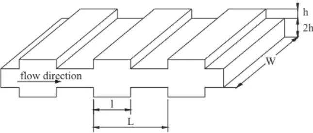
l L
h 2h W flow direction
Fig. 1 Dimensions of the grooved channels
Fig. 2 Entire experiment setup
①
②
③
④
⑤
⑥
⑧ ⑦
① Circulating tank
② Centrifugal pump
③ Control valve
④ Piston pump
⑤ Test zone
⑥ Differential transducer
⑦ Flow-meter
⑧ Overflow tank
Fig. 3 Diagram of the experimental system
3. Results and discussion
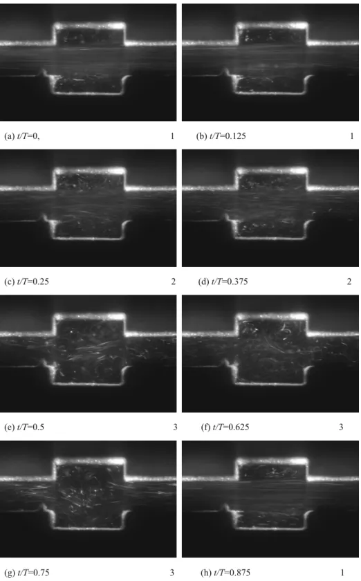
As is shown in Fig. 4 and Fig. 5, 4 kinds of flow patterns deserve attention for l = 10mm, P=1 and Re=570.The locations of all particles are almost motionless in Fig. 5(g), the intension of flow mixing is worst in this time, it belongs to “motionless” and marked as “0”. Two stable symmetric vortexes form in the grooved area and the pathlines of the main flow are parallel to each other in Fig. 4(a), it belongs to “stable” state and marked as “1”. The pathlines of the main flow are unstable, but vortexes form in the grooved area and the main flow can be distinguished in Fig. 4(c), it is marked as “2”. The flow in the grooved area and main flow can’t be distinguished in Fig. 4(e), the intension of flow mixing is best at this time, it is marked as “3”.
3.1 The effect of t/T on the flow patterns
Fig. 4 shows the flow patterns at Re=570, P=1, f=0.6160 and l=10mm, it can be seen that the unstable flow state occurs during the period of t/T=0.25-0.75, and the flow mixing at t/T=0.5-0.75 is better than that at t/T=0.25- 0.375, but the flow is stable during the period of t/T=0.875-0. It is because that the velocity of main flow is very high during the period of t/T=0.875-0 so that the flow of the main flow is stable. But the velocity of main flow is
(a) t/T=0, 1 (b) t/T=0.125 1
(c) t/T=0.25 2 (d) t/T=0.375 2
(e) t/T=0.5 3 (f) t/T=0.625 3
(g) t/T=0.75 3 (h) t/T=0.875 1
Fig. 4 Experimental flow patterns for Re=570, P=1, l=10mm and f=0.6160
3.2 The effect of frequency on the flow patterns
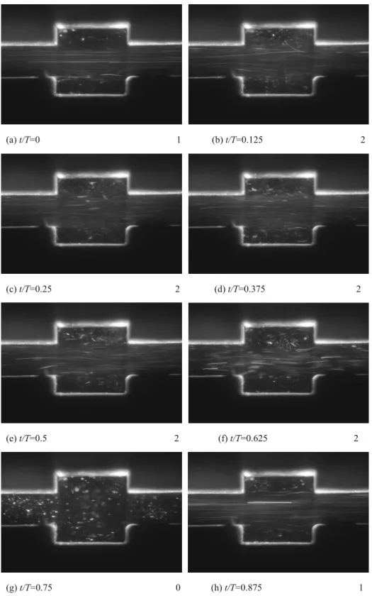
Fig. 5 shows the pulsatile flow patterns at Re=570, P=1, f=0.1173 and l=10mm, it can be seen that unstable flow state occurs during the period of t/T=0.125-0.625, the unstable flow is earlier than that at f=0.6160, a part of fluid in the mainstream flows into the grooves due to the flow in instability. The flow is almost at static when the period of t/T=0.75, and the instantaneous Reynolds number is 0 at this time. An interesting phenomenon can be discovered, it is no flow patterns that is similar to Fig. 4(e) at f=0.1173, so the heat mass transfer at f=0.6160 is better than that at f=0.1173.
(a) t/T=0 1 (b) t/T=0.125 2
(c) t/T=0.25 2 (d) t/T=0.375 2
(e) t/T=0.5 2 (f) t/T=0.625 2
(g) t/T=0.75 0 (h) t/T=0.875 1
Fig. 5 Experimental flow patterns for Re=570, P=1, l=10mm and f=0.1173
frequency even if the pulsatile flow in the different groove length.
Table 1 Stable and unstable state of flow patterns during a pulsating cycle for different frequency when Re=570, P=1 and l=10mm
Frequency t/T
f 0 0.125 0.25 0.375 0.5 0.625 0.75 0.875
0.0986 1 2 2 2 2 2 0 1
0.1027 1 2 2 2 2 2 0 1
0.1071 1 2 2 2 2 2 0 1
0.1120 1 2 2 2 2 2 0 1
0.1173 1 2 2 2 2 2 0 1
0.1232 1 2 2 2 2 2 0 1
0.1297 1 2 2 2 2 2 3 1
0.1369 1 2 2 2 2 2 3 1
0.1449 1 2 2 2 2 2 3 1
0.1540 1 2 2 2 2 2 3 1
0.1643 1 2 2 2 2 2 3 1
0.1760 1 2 2 2 2 3 3 1
0.1895 1 2 2 2 2 3 3 1
0.2053 1 1 2 2 2 3 3 1
0.2240 1 1 2 2 2 3 3 1
0.2464 1 1 2 2 2 3 3 1
0.2738 1 1 2 2 2 3 3 1
0.3080 1 1 2 2 2 3 3 1
0.3520 1 1 2 2 2 3 3 1
0.4107 1 1 2 2 3 3 3 1
0.4928 1 1 2 2 3 3 3 1
0.6160 1 1 2 2 3 3 3 1
Table 2 Stable and unstable state of flow patterns during a pulsating cycle for different frequency and groove length when Re=300 and P=1
groove
length Frequency t/T
l f 0 0.125 0.25 0.375 0.5 0.625 0.75 0.875
8
0.065 1 1 1 1 1 1 0 1
0.130 1 1 1 2 2 3 0 1
0.324 1 1 1 1 2 3 3 1
12
0.065 1 1 2 2 1 2 0 1
0.130 1 1 2 2 2 3 0 1
0.324 1 1 1 1 2 3 3 1
14
0.065 1 2 2 2 2 2 0 1
0.130 1 2 2 2 2 3 0 1
0.324 1 1 2 2 3 3 3 1
4. Conclusions
In this paper, experimental researches are conducted to explore the characteristics of the pulsatile flow in the grooved channel. The main conclusions are obtained as follows:
(1) The flow mixing intensity of the pulsatile flow in the grooved channel belongs to the deceleration phase is better than that during the acceleration phase, and the instability of the flow enhances with t/T during the deceleration phase.
(2) As the frequency increases, the onset of the unstable flow state is postponed, but the pulsatile flow pattern of “3” state starts to appear and advance gradually. The flow mixing intensity of the mainstream and the recirculation vortex increases as pulsatile frequency.
(3) As the increase of groove length, the onset of the unstable state gradually advances, the duration of the unstable state augments and the instability of the flow enhances.
Acknowledgment
This study is sponsored by the National Key R&D Program of china(2019YFB1504301) , the cooperative Research Program of IOES (No. 19A02) and the National Natural Science Foundation of China (No. 11972105).
References
[1] L.Y. Yongning BIAN, Hirofumi ARIMA, Yasuyuki IKEGAMI. Effect of groove length on fluid flow in grooved channels for pulsatile flow. OTEC 2014; 19: 1-6.
[2] H.A. Xiaoyu ZHANG, Yongning BIAN , Yasuyuki IKEGAMI. Characteristics of pulsatile flow with the same oscillatory fraction in a grooved channel. OTEC 2016; 21: 6.
[3] H.A. Han Huang, Yongning BIAN, Yasuyuki IKEGAMI. Pressure prop characteristics of laminar pulsatile flow in grooved channel with different groove lengths. OTEC 2017; 22: 1-8.
[4] Y.B. Junxiu PAN, Hirofumi ARIMA, Yasuyuki IKEGAMI. Characteristics of pulsatile flow with the reverse flow in the grooved channel. OTEC 2019; 24: 1-7.
[5] F. Zhang, Y. Bian, Y. Liu, et al. Experimental and numerical analysis of heat transfer enhancement and flow