JAIST Repository
https://dspace.jaist.ac.jp/
Title
System scenarios and technical requirements
Author(s)
Anwar, Khoirul; Khalife, Hicham; Komulainen,
Petri; Ma, Yi; Mariani, Filippo; Matsumoto, Tad;
Matthé, Maximilian; Natkaniec, Marek; Szott,
Szymon; Wszolek, Jacek; Yi, Na; Zhou, Xiaobo
Citation
ICT-619555 RESCUE D1.1 Version 2.0: 1-42
Issue Date
2014-04
Type
Research Paper
Text version
publisher
URL
http://hdl.handle.net/10119/13791
Rights
This material is posted here by permission of the
EU FP7 RESCUE Project. http://www.ict-rescue.eu/
RESCUE is founded by the European Commission
under the 7th Framework Programme,Theme
3-"ICT"call FP7-ICT-2013-11,Work Programme Topic
1.1"Future Networks"
ICT- 619555 RESCUE
D1.1 Version 2.0
System scenarios and technical requirements
Contractual Date of Delivery to the CEC: 04/2014 Actual Date of Delivery to the CEC: 05/2014 Editor: Petri Komulainen
Authors: Khoirul Anwar, Hicham Khalife, Petri Komulainen, Yi Ma, Filippo Mariani, Tad Matsumoto, Maximilian Matthé, Marek Natkaniec, Szymon Szott, Jacek Wszolek, Na Yi, Xiaobo Zhou
Participants: AGH, JAIST, TCS, TUD, UBITECH, UNIS, UOULU Work package: WP1 - Theoretical analyses for limit and rate-distortion region Estimated person months: 30
Security: PU
Nature: R
Version: 2.0
Total number of pages: 42
Abstract: The RESCUE project – “Links-on-the-fly Technology for Robust, Efficient, and Smart Communication in Unpredictable Environments” – introduces a communication concept based on distributed turbo codes, targeted for multi-hop communication in mesh networks that are subject to dynamic topology changes. This deliverable describes two potential system scenarios, i.e., network layouts with communication applications, where the RESCUE system can in practice improve reliability and spectral efficiency. The first scenario is public safety operations that take place in areas where the communication infrastructure is partially inoperable due to a disaster such as an earthquake. The second scenario is vehicle-to-vehicle (V2V) communication, where cars and other vehicles share, for example, safety-critical information about the road and traffic conditions with each other. The key functional requirements and design challenges for different protocol layers, from the physical to the network layer, are also listed. The document provides a framework for the research and validation work in the project, from analyses and simulations to field trials.
Keyword list: distributed turbo code, lossy links, multi-hop communication, public safety, vehicle-to-vehicle, wireless networks
Executive Summary
The basis of the RESCUE project is in the design and research of a novel communication concept called “links-on-the-fly”. This technology design is targeted for multi-hop communications in largely unplanned mesh networks that are further subject to dynamic topology changes. Firstly, the design takes advantage of the inherent broadcast nature of the radio channel, and the multi-route diversity of the mesh network so that the communication reliability increases, and the outage probability reduces. Secondly, the overall spectral efficiency and communication range are enhanced by the fact that even the erroneously decoded data packet transmissions are utilized, as the relay nodes may re-encode and re-transmit them towards the destination. The underlying idea is that the different transmitting nodes in the network form together a distributed turbo code that the destination can iteratively decode even if the channel (link) conditions between different nodes are mainly unknown. One of the main challenges of the RESCUE project is to discover efficient “soft” routing protocols that support distributed turbo coding under topology changes, and can facilitate a variety of unicast and multicast services.
One potential practical framework for the links-on-the-fly concept is public safety operations that take place in areas where the communication infrastructure is partially inoperable due to a disaster such as earthquake. In a fast emergency network roll-out the destinations may be multiple wireless hops away from the originating transmitters. Furthermore, the nodes may be moving, which results in changing channel conditions, where the changes are often unpredictable, and – in larger scale – network topology changes. The traditional public safety applications to be supported are push-to-talk (PTT) and automatic person/vehicle location (APL/AVL), but more advanced services such as video streaming are highly valuable for public safety operations as well. Another potential framework is vehicle-to-vehicle communication. Here, cars and other vehicles share, for example, safety-critical information about the road and traffic conditions with each other. The vehicles form a dynamic ad hoc network, where the node distances and the channel conditions may vary greatly as a result of constant node movements. Thus, the network is subject to frequent topology changes, and the main challenge is in the design of a routing protocol that is always able to react rapidly enough.
The identified communication applications such as video streaming, text messaging, group communication (push-to-talk), geographic location services (APL/AVL), and cooperative collision warning, have all somewhat different quality-of-service (QoS) requirements in terms of throughput and latency. Furthermore, the multi-hop and multi-route network structure sets a variety of functional requirements for the different protocol layers, from the physical layer to the network layer. Especially, new designs for coding and decoding, rate control, medium access control (MAC), routing, node coordination, and automatic-repeat-request (ARQ) protocols are needed. Additionally, wireless channel access and multi-antenna transmission methods matching with the RESCUE system scenarios and links-on-the-fly concept should be sought.
One important objective of this document is to lay ground for the algorithm research work in the RESCUE project by describing the main use case scenarios, applications, and conditions. Various levels of research and validation will be carried out: information theoretic analyses, model-based numerical simulations, over-the-air (OTA) testing, and – for a proof-of-concept – field trials employing programmable software-defined-radio (SDR) platform devices. Furthermore, a channel measurement campaign will be carried out in order to obtain a measurement-based vehicle-to-vehicle (V2V) channel model. The chosen scenarios and equipment for the OTA testing, field trials, and channel measurements are described in another RESCUE deliverable [D41].
Authors
Partner
Name
E-mail / Phone
AGH University of Science Marek Natkaniec [email protected] and Technology Szymon Szott [email protected]
Jacek Wszolek [email protected]
Japan Advanced Institute Tad Matsumoto [email protected] of Science and Technology Khoirul Anwar [email protected] (JAIST) Xiaobo Zhou [email protected]
Technical University Dresden Maximilian Matthé [email protected] (TUD)
Thales Communications & Hicham Khalife [email protected] Security SAS (TCS)
UbiTech Limited Filippo Mariani [email protected]
University of Surrey Yi Ma [email protected]
(UNIS) Na Yi [email protected]
University of Oulu Petri Komulainen [email protected] / +358 294 482971 (UOULU) Tad Matsumoto [email protected]
Table of Contents
Executive Summary ... 2
Authors... 3
Table of Contents ... 4
List of Acronyms and Abbreviations ... 5
1.
Introduction ... 7
1.1 RESCUE system introduction ... 7
1.2 Theoretical background ... 9
1.2.1 Cooperative relaying protocols ... 9
1.2.2 Decode-and-forward relaying allowing intra-link errors ... 10
1.2.3 Lossy and lossless networks ... 10
1.2.4 Slepian-Wolf rate region ... 11
1.2.5 Distributed turbo code ... 12
2.
Scenarios ... 14
2.1 Public safety operations ... 14
2.1.1 Common public safety solutions ... 15
2.1.2 Situational model ... 18
2.1.3 Communication case ... 19
2.1.4 Wireless characteristics ... 21
2.2 Vehicle-to-vehicle and group communication ... 23
2.2.1 State of the art: standards for multichannel VANETs ... 24
2.2.2 Situational model and network characteristics ... 26
2.2.3 Special communication applications ... 28
2.2.4 Wireless characteristics ... 29
3.
Functional requirements ... 31
3.1 Physical layer ... 31
3.1.1 Channel coding and decoding ... 31
3.1.2 Wireless access and multi-antenna transmission ... 32
3.1.3 Multi-rate support ... 33
3.2 Data link and network layers ... 33
3.2.1 Medium access control (MAC) ... 33
3.2.2 Automatic repeat request (ARQ) protocol ... 34
3.2.3 Multi-rate control ... 34
3.2.4 Routing ... 34
3.2.5 Node coordination ... 34
4.
Conclusion ... 36
5.
References ... 37
Appendix A Simulation models ... 40
A.1 Link-level channel model ... 40
A.2 Fundamental network topology model ... 40
A.2.1 Switching between lossless and lossy links ... 40
A.2.2 Switching between LOS and NLOS links ... 41
List of Acronyms and Abbreviations
Term Description
3GPP 3rd Generation Partnership Project
AF Amplify-and-Forward
APL Automatic Person Location ARQ Automatic Repeat Request AVL Automatic Vehicle Location
BER Bit-Error Rate
BSM Basic Safety Message
CAM Cooperative Awareness Message CBF Contention-Based Forwarding
CEPT European Conference of Postal and Telecommunications Administrations CF Compress-and-Forward
CFO Carrier Frequency Offset CRC Cyclic Redundancy Check
CSMA/CA Carrier Sense Multiple Access With Collision Avoidance D2D Device-to-Device
DENM Decentralised Environment Notification Message
DF Decode-and-Forward
DMO Direct Mode
DSRC Dedicated Short-Range Communications
ETSI European Telecommunications Standards Institute FCC Federal Communications Commission
FER Frame-Error Rate
GFDM Generalized Frequency Division Multiplexing GPS Global Positioning System
GSM Global System for Mobile Communications IDMA Interleave Division Multiple Access
IEEE Institute of Electrical and Electronics Engineers ITS Intelligent Transportation System
LLR Logarithmic Likelihood Ratio
LOS Line-of-Sight
LTE Long-Term Evolution MAC Medium Access Control MUD Multiuser Detection NLOS Non-Line of Sight
OCB Outside the Context of a Basic Service Set OFDM Orthogonal Frequency-Division Multiplexing OLSR Optimized Link State Routing
OTA Over-the-Air
P2P Point-to-Point
PAPR Peak-to-Average Power Ratio
PHY Physical Layer
PMR Professional Mobile Radio
PPDR Public Protection and Disaster Relief
PTT Push-to-Talk
QAM Quadrature Amplitude Modulation QoS Quality of Service
QPSK Quadrature Phase-Shift Keying
RESCUE Links-on-the-fly Technology for Robust, Efficient, and Smart Communication in Unpredictable Environments
RSU Radio Station Unit SDR Software-Defined Radio SMS Short Message Service SNR Signal-to-Noise Ratio
TETRA Terrestrial Trunked Radio TTC Time-to-Collision V2V Vehicle-to-Vehicle
VANET Vehicular Ad Hoc Network
WAVE Wireless Access in Vehicular Environment WLAN Wireless Local Area Network
1.
Introduction
The massive earthquakes including series of aftershocks hit the Tohoku and Kanto areas in Japan on March 11, 2011, followed by unprecedentedly huge tsunami waves of up to 40m height, after which numerous base stations of commercial mobile communication systems lost their proper operability. The resulting communication blackout clearly indicates that there is a need for robust technologies that can retain coverage even when the infrastructure is sparse or partially damaged. It is also highly desirable that the remaining infrastructure can be readily extended and integrated with fast ad hoc emergency wireless network roll-outs consisting of temporary or moving nodes.
One distinctive feature in a network consisting of temporary or moving nodes is that the destination may be multiple wireless hops away from the originating transmitter. Another property is that the network easily ends up having a non-hierarchical mesh structure, where the connections between nodes are unplanned and the link qualities unpredictable. Thus it is likely that there exist multiple useful multi-hop routes from the source to the destination.
The RESCUE project – “Links-on-the-fly Technology for Robust, Efficient, and Smart Communication in Unpredictable Environments” – brings forth a communication technology design targeted for multi-hop communication in largely unplanned mesh networks that are further subject to dynamic topology changes. Firstly, the design takes advantage of the inherent broadcast nature of the radio channel, and the multi-route diversity of the mesh network. Secondly, the spectral efficiency is increased by using a distributed coding method where also the erroneously decoded data packet transmissions are utilized, as the relay nodes may re-encode and re-transmit them towards the destination.
This deliverable describes two potential system scenarios, i.e., network layouts with communication applications, where the RESCUE system can in practice improve reliability and spectral efficiency. The first scenario is public safety operations that take place in areas where the communication infrastructure is partially inoperable due to a disaster such as an earthquake. The second scenario is vehicle-to-vehicle (V2V) communication, where cars and other vehicles share, for example, safety-critical information about the road and traffic conditions with each other. The key functional requirements and design challenges for different protocol layers, from the physical to the network layer, are also listed.
One important objective of this document is to lay ground for the algorithm research work in the RESCUE project by describing the main use cases, applications, and conditions. Various levels of research and validation will be carried out: information theoretic analyses, model-based numerical simulations, over-the-air (OTA) testing, and – for a proof-of-concept – field trials employing programmable software-defined-radio (SDR) platform devices. Furthermore, a channel measurement campaign will be carried out in order to obtain a measurement-based V2V channel model. The chosen scenarios and equipment for the OTA testing, field trials, and channel measurements are described in another RESCUE deliverable [D41].
1.1
RESCUE system introduction
One of the important aspects for emergencies is the great importance of comprehensive and effective emergency management. This management is the combination of interlinked phases/responsibilities. In all these phases, communication is a major requirement for effective coordination of response operations in order to retain and maintain public safety. It also shows how much the public safety sector depends on the collection of information in such situation. It requires robustness, reliability, and high spectral efficiency, not only in terms of point-to-point communication, but also in terms of the networks. Currently, the most widely used communication systems in the case of an emergency are public protection and disaster relief networks (PPDR) such as Terrestrial Trunked Radio (TETRA) [TETRA, Gra03] and TETRAPOL. However, in the future, public safety networks and operators are expected to migrate towards broadband wireless communication systems and standards, i.e., LTE [GSB11]. One of the reasons for this migration is the larger available bandwidth of LTE enabling richer public safety services, applications and better call-quality [DDT+13]. In such critical networks, a means of communication can be provided by careful planning, deployment and efficient operation of the infrastructure.
However, one asset that might be severely destroyed in case of a catastrophe is the communication infrastructure itself. For example, in the case of the tsunami in Japan [JPN13], equipment was submerged
by the flooding, cables were cut-off or even unburied from underground, telephone poles were ripped out. Other equipment that was not broken stopped operating after battery life depleted due to long lasting commercial power outage. Even more problematically, the appropriate operation of the communication network is attacked from both sides, the limited capacity provided by the remaining infrastructure and the increasing communication demand of people who are concerned about the wellbeing of relatives, family members, and friends which causes network congestion and service saturation. Thus, means are required to distinguish different services and users in order to prioritize the exchange of data that is vital for public safety. This is increasingly difficult, because in the world of tomorrow such communication will not only relate to PPDR personnel, but also to all kinds of other sensors and devices, i.e., Device-to-Device (D2D) and smart cities
This background motivated us to establish a theoretical, technological, and practical basis for a novel communications technology design that efficiently utilize the characteristics of future wireless networks, which are expected to be dense in terms of node and link populations, and heterogeneous in terms of their built-in capabilities. A network design based on these principles is expected to be robust and flexible towards the destruction of infrastructure but also energy and spectral-efficient.
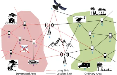
Devastated Area Ordinary Area
Lossy Link Lossless Link A B C D E F P Q R Z T U V X Y S
Figure 1.1: Typical public safety theater deployment.
Links-on-the-fly is a novel concept for robust, efficient, and smart information transmission in
unpredictable environments which are characterized by substantial and sudden changes of the network’s
structure. The concept integrates the key technologies:
Distributed joint source/channel coding in lossy wireless networks,
Modern signal processing and coding/decoding algorithms (such as distributed turbo coding), Exploitation of multi-route information transfer in wireless multi-hop networks,
Distributed and centralized MAC/network protocols for channel access, and routing, Cross layer design for interference management and error control.
Links-on-the-fly achieves:
Successful and robust information transfer through multi-path networks that are constructed from lossy point-to-point links (increase of coverage),
Adaptability of information quality to the specific quality of service (QoS) requirements of applications and devices for higher spectrum and energy efficiency,
The integration of diverse communication infrastructure such as base stations, relays, and satellites, and terminals for network robustness and fast provision of communication services (e.g. in case of disasters).
The conventional multi-hop/mesh networks are designed on the basis of lossless links, and they are not optimal for fragile public-safety networks because:
does not foresee the case of huge disasters due to the potential destruction of large parts of the infrastructure.
The required very strong coding techniques on each link causes heavy power consumption due to the decoding complexity.
As a major benefit, network design according to the links-on-the-fly concept does not have to use the accurate/strict link budget design, and it includes the whole spectrum of diverse communication infrastructure as depicted in Figure 1.1 including satellites, multi-hop communication through various terminals, which can also be carried on cars, airplanes, helicopters or even drones, etc. Furthermore, by accepting the specified level of loss/distortion, the rate/power requirements to be allocated to each link/node can be significantly reduced in the network as a whole. At the same time, robustness of the network is significantly enhanced. The expected result of this project is, hence, the key to a technological basis for the design of secure, reliable, and energy as well as spectrally efficient networks of many nodes/links that are potentially unreliable. Another important factor is that given the global requirements and recognition of the importance towards building eco-friendly society, creating new broadband wireless communication network concepts that perform close to the network-level limits of energy and spectrum efficiencies (as described e.g. in [EK11]), and operate beyond the traditional point-to-point (P2P) communication paradigm, is an urgent demand the achievement of which would constitute a major enhancement coming with future broadband wireless communications systems beyond LTE-Advanced.
1.2
Theoretical background
Almost 20 years have passed since the discovery of turbo coding technique by Berrou et al. [BGT93] that achieves near Shannon capacity on P2P links. Based on the turbo concept, as a backbone technique of commercial communication systems where the channels connecting a base station and the users are an assembly of the P2P links, many new techniques have been created. However, the cellular communications systems based on the capacity-achieving P2P link design are found to be vulnerable to network topology changes. The recognition of this vulnerability has invoked a paradigm-shift of the turbo concept from P2P optimization to network-level optimization where the network, as a whole, is regarded as a distributed turbo code.
1.2.1
Cooperative relaying protocols
One core technology employed by the links-on-the-fly concept is cooperative relaying. Based on the signal processing performed at the relay upon its received signals, relay protocols can be classified into three major categories [KGG05]: amplify-and-forward (AF), compress-and-forward (CF) and decode-and-forward (DF). In the AF protocol, the relay simply scales its received signal according to its power constraint and forwards the scaled signal to the destination. The destination then makes decisions by properly combining signals transmitted from the source and relays. In the CF protocol [KGG05], the relay retransmits a quantized and compressed version of the received signal to the destination, where the Wyner-Ziv coding (WZC) technique [WZ76] may be employed to exploit the statistical dependence between the relay and the destination. Finally, in the DF protocol, the relay first decodes the received signals and then re-encodes before transmitting it to the destination, therefore additional error protection can be provided.
The limiting factor in AF relaying is the noise amplification [MGM12], whereas the CF inherently introduces compression noise/distortion [HZ05]. Furthermore, the CF results in signal bandwidth expansion, depending on what kind of quantization is used. For DF, the main problem is error propagation, which takes place when the relay is unable to decode correctly.
When the channel quality of the source-relay link is good, the DF based cooperation scheme outperforms the AF and CF based schemes. However, AF and CF based cooperation schemes are more advantageous if the source-relay link suffers from a deep fade [LHQ+12]. To exploit the merits of both DF and AF/CF, some advanced schemes have been proposed, which are referred to as hybrid DF/AF [BLH10, ZWZ13] and hybrid DF/CF [HL06, SVL09]. In the hybrid schemes, the basic idea is to use DF when the relay can decode successfully, and AF or CF otherwise.
The RESCUE cooperative relaying protocol consists of DF that allows intra-link errors, combined with distributed turbo coding that brings improved error protection. The relaying nodes decode and re-encode the data, which causes no bandwidth expansion compared to the original signal. The possible decoding errors at the relaying nodes results in limited correlation between the forwarded packet copies. The
decoding errors can be modeled by a bit-flipping model at the destination. These basic principles of the RESCUE relaying strategy have been presented in [AM12, ZCA+12, ZHA+12]. Other cooperative relaying strategies such as compress-and-forward (CF) will also be addressed in the project to see how they relate or fit to the “links-on-the-fly” concept.
1.2.2
Decode-and-forward relaying allowing intra-link errors
In the distributed turbo code concept, the relay nodes – that are on parallel routes from the source to the destination – apply different interleaving patterns when re-encoding the same data packet. At the destination, the differently encoded copies are combined via iterative decoding that may correct the decoding errors that occurred at the relays. Thus, even though the quality of a link on one parallel route (intra-link quality) drops to a level that is lower than designed, the end-to-end communication may well be successful. Furthermore, by utilizing a bit-wise reliability compensation function that employs the knowledge of the intra-link error probabilities, error probability at the destination can further be reduced. This structure is found to be supported by the correlated source coding theorem, known as Slepian-Wolf theorem in Network Information Theory.
The benefits of allowing intra-link errors in cooperative wireless networks are summarized as follows: The information frames received at the relay node found to contain errors are not discarded but further interleaved, re-encoded, and transmitted to the next stage. By allowing the frames having intra-link errors to be forwarded, we can preserve many parallel links, some part of which may have mesh-structure, and hence we can expect significant diversity gains and reduction of the system outage.
The reliability of the end-to-end connection is improved by link or route diversity under unpredictable link gain variations, or even topology changes. Different combinations of parallel intra-link channel gains form an admissible rate region, inside which any rate combination enables lossless end-to-end communication. This effect significantly reduces the outage probability of the system.
Conversely, when the system is in a stable and predictable situation, even if the source entropy is larger than the rate supported by the channel, still source information can be recovered with the correlated source detection technique. This yields higher spectrum efficiency than the conventional techniques based on P2P optimization techniques.
Since the achievable rate of an end-to-end connection depends on the aggregate of qualities of multiple parallel routes, the link budget can be more flexibly allocated in terms of transmit power.
The probabilities of the intra-link errors can be estimated only at the destination (or also at the relay nodes, if the network, in part, has mesh structure), and hence no side-channel is needed. The logarithmic-likelihood-ratio (LLR) exchange is performed at the destination (or also at the relay nodes, if the network has mesh structure), where reliability compensation reflecting the intra-link qualities (or more drastically, it reflects the appearance/disappearance of the intra-links) is performed by the LLR updating function that follows the intra-link error probability estimation, yielding significant robustness against the network topology variation. This concept is referred to as “link-on-the-fly” principle.
If some level of distortion, e.g., 10-5 bit-error-rate (BER) or 10-3 frame-error-rate (FER), is accepted after the decoder at the final destination (referred to as lossy communication), we can further broaden the admissible rate region, resulting in further robustness of the network. The distortion appears in the form of error floor in BER or FER curves versus received SNR. With the system design based on this concept, we can expect significant reduction in required transmit power, while keeping the outage probability of the system as required.
1.2.3
Lossy and lossless networks
Let us define the terms lossless and lossy networks:
Lossless network has at least one tandem connection, i.e., a set of consecutive links, where the data remains error-free before it is interleaved and re-encoded at each relay node. The problems related to this network structure can be classified into the category of lossless Slepian-Wolf
correlated source coding with helpers. This system setup is exemplified as shown in Figure 1.2 (a).
Lossy network is a network where there is no tandem connection of links where the data remains error-free before re-encoding at every relay node. The problems related to this network structure can be classified into the category of lossy correlated source coding, such as chief executive officer (CEO) problem. This system setup is exemplified as shown in Figure 1.2 (b).
(a) (b)
Figure 1.2: Examples of (a) lossless and (b) lossy networks. A dashed arrow indicates that the receiver is unable to decode the transmitted sequence error-free.
A complex network can be decomposed into some component networks, where the transmission chain structure and its related parameters can be optimized separately, but not network as a whole, since the theoretical limits are known only for specific network structures. In the networks, where the network nodes are densely populated, it is likely that there exist several routes, even though the connection of each link is relatively unstable. This indicates that some of the links guarantee lossless communications while the others do not. However, the estimated information sequences, obtained at the destination by decoding the multiple signals, conveyed via the multiple routes, are highly correlated. Hence, even though some links cannot guarantee the lossless communication, it is still possible to recover the transmitted information at the destination with some levels of distortion lower than specified.
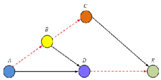
Figure 1.3 shows an example of a lossy distributed cooperative network, where there are no error-free tandem connections between the source A and the destination E. This network can be further decomposed into a lossless and a lossy network, as shown in Figure 1.2.
Figure 1.3: An example of a lossy network.
1.2.4
Slepian-Wolf rate region
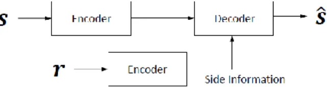
The theoretical background of the simplest cooperative communication system, one-way relaying allowing intra-link errors, can be related to the source coding theory with side information. An exemplifying block diagram is shown in Figure 1.4. Here, the source aims to transmit the information sequence s, and the destination aims to recover s with aid of the side information r provided by the helper. In order to help in the recovery of s, side information r must be correlated with s.
The encoders at the source and at the helper adjust their compression rates, Rs and Rr, with the aim to minimize the signalling load while facilitating error-free recovery of the messages by the decoder. The
admissible rate region of the source and the helper is shown in Figure 1.5, where notation H(∙) denotes
entropy of the argument. The rate region for the case of two independent (uncorrelated) sources is shown in the rectangular indexed by “independent”.
Figure 1.4: Source coding with side information.
The Slepian-Wolf [SW73] admissible rate region for two correlated sources is indexed by A3, where the assumption is that both messages s and r need to be decoded. Obviously, it is found that the region A3 is much larger than the case where the two sources are independent, resulting in decrease of the required transmission rates.
Figure 1.5: Admissible rate regions for Slepian-Wolf system and source transmission with a helper. When applying the Slepian-Wolf system concept to the simple one-way relay system (shown in Figure 1.2 (a)), the helper’s sequence r is an erroneous version of the original sequence s. Thus, the decoder does not need to recover r. Hence, when viewing the way relaying systems from the one-helper Slepian-Wolf theorem, the admissible rate region is the area shown above the red curve in Figure 1.5. This region corresponds to the case where the helper’s information (or relayed sequence) is only used to recover the original source information, and the relayed information does not have to be fully recovered. It is found that, however, the admissible rate region with one helper can be well approximated by the region “A3 plus A4”, when only the source information is intended to be correctly recovered.
1.2.5
Distributed turbo code
As stated before, cooperative communication network can be seen as a distributed turbo code. In this scenario, encoding at each node provides error protection instead of compression. On the other hand, the “compression” is induced by the limited radio channel capacity in each link, which restricts the successful point-to-point transmission rate. If the rate set supported by the channels falls within the admissible rate region, the decoder is again able to successfully decode the transmitted data. Here, the boundary of the admissible rate region can be approached by adjusting the transmit powers. In this case, the cooperative relaying provides savings in terms of required SNR.
Since the channel gains change due to fading, the outage for the end-to-end connection happens when the rate pair falls outside the admissible rate region. The average outage probability is the probability averaged over the probability density function of the link gain variations of the links. Furthermore, the link variation property largely depends on the propagation characteristics of the link gains, e.g., the links are composed of none-line-of-sight (NLOS) components only, or some of them contain line-of-sight (LOS) components. When there is no tandem connection having no errors after channel decoding at the nodes (lossy case), the outage calculation is much more complicated. This will be the most challenging part of this project.
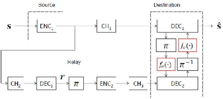
Figure 1.6: A block diagram of the one-way relay system allowing intra-link errors from the viewpoint of distributed turbo code.
A block diagram of the simple one-way relay system allowing intra-link errors, corresponding to the network shown in Figure 1.2 (a), and seen from the viewpoint of a distributed turbo code, is shown in Figure 1.6, where the decoder is shown on the right hand side of the figure. The box “fc(•)” is the LLR updating function that performs the “compensation” of the LLR values due to the limited correlation between the two signals. “fc(•)” utilizes the knowledge of the correlation between the information parts of the signals transmitted from the source and the relay.
This structure, including the whole transmission chain, matches with what the Slepian-Wolf theorem for the correlated source coding states: If the rate set supported by the channels falls into the admissible region, and if the joint decoder at the destination can utilize the correlation knowledge between the information sequences, the transmitters can independently encode and transmit the information sequence, and they do not have to negotiate over the code parameters to be used.
Furthermore, because of the source-channel separation theorem, source and channel coding can also be performed independently, so far as the rate set falls into the admissible region. Hence, the fundamental supporting theory to the “link-on-the-fly” system is lossless/lossy distributed correlated joint source-channel coding, where the signals transmitted from the relays are regarded as helpers.
Analysing the admissible rate region for the lossless transmission may not be intractably difficult, but in lossy case, the complete analysis is expected to be significantly difficult and requires a lot of effort. Furthermore, when the variety of applications such as V2V and group-to-group communications are considered, the characterization of the change of channel property plays important roles, which invokes the necessity of modelling of the channel property change.
2.
Scenarios
This chapter describes potential use case scenarios and communication applications with varying QoS requirements for the RESCUE system. State-of-the-art solutions and standards are also reviewed. The first practical framework for the links-on-the-fly concept is public safety operations that take place in areas where the communication infrastructure is partially inoperable due to a disaster such as earthquake. Another potential framework is vehicle-to-vehicle (V2V) communication. Here, cars and other vehicles share, for example, safety-critical information about the road and traffic conditions with each other.
2.1
Public safety operations
Crises may happen everywhere in the world, thus a force of intervention must be able to react to any emergency situation, despite of the environmental conditions and their equipment. It is commonly accepted that one of the best ways to ensure a prompt and effective intervention is to provide and maintain cooperation between members of the team, as well as cooperation with external elements such as, for instance, a command and control unit (C2).
Figure 2.1: Traditional public safety scenario.
In order to achieve the required communication objectives, public safety operators rely on dedicated networks that ensure specific services highlighted in Figure 2.1. In practice, these networks have similarities with civil mobile cellular networks with the main following differences:
Public safety networks operate on dedicated spectrum bands specifically dedicated for the rescue operations. Indeed Public Protection and Disaster Relief (PPDR) operations exploit the 400 Mhz band in Europe and the 700 Mhz in the US.
Public safety networks are managed by dedicated operators with the main objective of ensuring high resilience and reliability.
Most PPDR deployments today are based on the TETRA standard. This standard is very similar to the GSM (2G) standard with a main focus on voice communication and very limited capacity for DATA exchange (refer for TETRA description above).
The main additional feature introduced for in the TETRA standard is the Direct Mode Operation (DMO). This feature enables device to device communications (monitored by the access point) thus extend the network coverage and access rescuers outside the range of base stations.
The LTE technology is foreseen as the future PPDR standard in Europe and the US. Public safety providers will operate LTE over the same LTE bands thus offering additional capacities and services during the relief operations.
With the increase of throughput and the evolution towards an IP based architecture connecting the public safety networks to a command and control C2 will become easier. This will allow a real time management, planning and coordination of rescue operations.
Historically, two main services are required during relief operations by public safety workers. These services are already supported by existing PMR networks since they require limited throughput to operate.
Automatic Person/Vehicle location (APL/AVL) service aims at distributing to all participants in the relief operation the GPS coordinates of public safety workers. This service is achieved through a synchronized network where each worker broadcasts periodically its position that is then conveyed and shared with all other rescuers. Clearly, exploiting the new generation of devices to distribute images, videos, and even voice recording from the scene can be of an extreme importance for rescue workers. These new type of information are even more important and pertinent when coupled to the exact geographical positions of participants (already offered by the APL classical tracking).
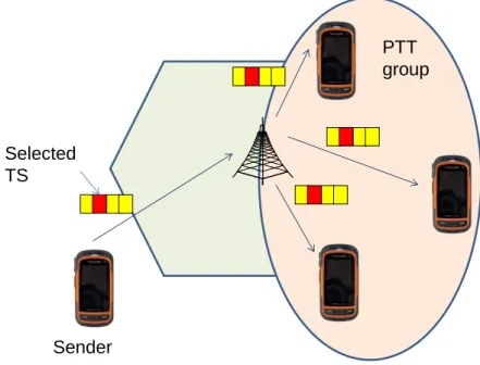
Another service in public safety operations is the Push-to-talk (PTT) communication. The PTT allows walkie-talkie like communications between rescuers. It enables only voice point to multi-point communications with limited throughput. This group communication solution is based on a TDMA access technique where a circuit is established to multiple receivers over the same time slot (as shown in the figure below). These timeslots are allocated and released manually by the sender. Clearly, adding to the half-duplex voice communication, video and/or data services can help save lives in a rescue area.
PTT
group
Sender
Selected
TS
Figure 2.2: Push-to-talk communication.
2.1.1
Common public safety solutions
TErrestrial Trunked RAdio (TETRA) is a digital trunked mobile radio standard developed by ETSI to meet the needs of traditional Professional Mobile Radio (PMR) user organisations such as:
• Public Safety • Transportation • Government • Military • Oil & Gas
• Wide area group communication i.e. one to many communication pattern
• Direct Mode Operation (DMO) allowing one hop Device to Device (D2D) communications The TETRA recent specifications [ETR300-1] were developed explicitly to give a multi-media radio platform able to support simultaneous voice, data and image applications to each radio platform. This capability was deemed attractive to the potential market and by incorporating it on to a single radio platform minimized the blocking and intermodulation problems common with other multi-function radios.
The radio access protocol is based on a four slot per carrier TDMA arrangement. The protocol is sufficiently flexible to allow four independent circuit mode applications (i.e. voice or circuit mode data) and/or any number of independent packet data applications to be simultaneously supported, up to the limit of the capability of the radio or the channel capacity of 28,8 kbit/s (gross) 19,2 kbit/s (net).
TETRA radio layer (Air Interface) parameters defined in [ETSI TS 100 392] and [ETSI EN 300 396] are summarized below in Table 2.1 and Table 2.2.
Table 2.1: TETRA infrastructure mode.
Table 2.2: TETRA direct mode operation.
Two separate technology families exist today to provide wireless communication: the commercial cellular networks and dedicated public safety solutions. Today industry and standardization bodies are pushing towards the convergence on a single technology of both families. Considerable efforts have been conducted at 3GPP to include public safety requirements in the coming LTE releases (Release 12). [ETSI-PS].
The main enhancements to the current LTE standards in order to address public safety operations are the following:
Proximity services that reproduce the direct mode (DMO) enabled in the TETRA standard. Group call feature that supports the fundamental requirement for efficient and dynamic group communications operations such as one-to-many calling.
Ongoing discussions today are advocating for the use of LTE technology over the already dedicated public safety spectrum bands. 3GPP is now in the process of designing technical standards to meet the first phase of broadband public safety requirements. Work is still on going to identify and prioritize other enhancements needed for LTE. Both commercial cellular and public safety systems need to be able to survive network equipment failures and overload situations but the requirements for public safety are more rigorous. In June 2013 3GPP agreed to study how to enhance the resilience of LTE networks for public safety applications.
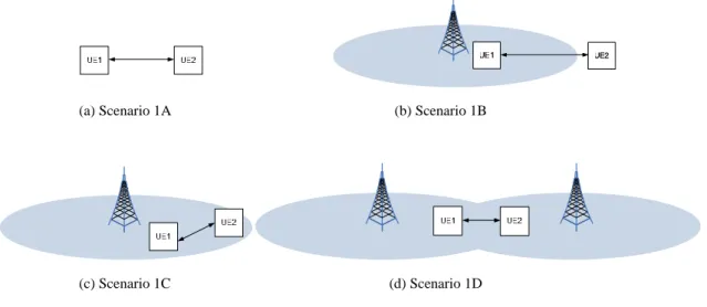
Precise network characteristics are in early phase of specification. They define the proximity services as a single hop network extension as shown in Figure 2.3 below.
(a) Scenario 1A (b) Scenario 1B
(c) Scenario 1C (d) Scenario 1D
Figure 2.3: LTE proximity services.
Table 2.3 below, obtained from the 3GPP technical specification [3GPP TR 36.843], compares the LTE deployment in general LTE and public safety scenarios.
Table 2.3: LTE general and public safety scenarios.
General Scenarios Public Safety Scenarios Carrier Frequency
(Note: The performance at 2GHz is expected to be different from the performance at 700MHz.)
2GHz 700 MHz
System bandwidth 10MHz Uplink and 10MHz Downlink for FDD, 20 MHz for TDD
10MHz Uplink and 10MHz Downlink for FDD, 20MHz for TDD for in-coverage and partial coverage scenarios,
10MHz dedicated spectrum for out-of-coverage scenarios
Network operation 100% eNodeBs enabled 0% eNodeBs enabled 100% eNodeBs enabled
3-site clustered eNodeB enabling pattern for 19 cells layout as shown in Figure A.2.1.1-1 for partial network coveragea
UE out of coverage criterion
N/A Average SINR < -6 dB over system
bandwidth. UE mobility (only
used for small scale Doppler modeling of channels)
3 km/h 60km/h for outdoor UEs in Option 5. 3km/h for all other cases.
UE RF parameters Max transmit power of 23 dBm for non public safety, 23 dBm, 31 dBm for public safety
1 Tx (2 Tx optional for public safety only), 2 Rx antenna, Antenna gain 0 dBi, Noise figure 9 dB
Total number of active UEsb per cell areac
Indoor-outdoor mix: 25 Indoor-outdoor mix: 10 Uniform (outdoor): 10 Hotspot: 10
Total number of UEs (including active UEsb) for discovery per cellc
Indoor-outdoor mix: 150 Indoor-outdoor mix: 150 Uniform (outdoor): 150 Hotspot: 150 Number of UEs participating in a D2D communication session Unicast : 2 Groupcast: N/A Broadcast: N/A Unicast: 2
Groupcast: 10 (One transmitter UE and 9 (Ngr) receiver UEs)
UE association for Relay D2D communication
N/A First UE is randomly selected from all UEs without eNodeB coverage and 2nd UE is selected from the UEs within eNodeB coverage
Minimum distance between eNodeB and building centere
100 m Minimum distance between UE and eNodeB >=35m Minimum distance between UEs >= 3m
Wraparound Wraparound is used for all cases except partial network coverage, for which no wraparound is used. Minimum association RSRP for D2D communication (X) (baseline) -112dBm
2.1.2
Situational model
Nevertheless, in many cases communication links cannot be maintained due to numerous factors. First, in the most common case, rescuers operate outside the coverage range of base stations. Indeed, the higher the distance between communicating entities, the lower the SNR and the higher the loss rate over that link. Second, in some extreme catastrophe conditions, the communication infrastructure can be partially destroyed. The RESCUE project tackles these particular issues by proposing an innovative coding technique for lossy links. These losses can be either caused by long communication distances or the partially destroyed infrastructure. The RESCUE project focuses particularly on the latter case. The focus is on relief operations taking place in urban areas where the rescuers are densely deployed.
In order to maintain connectivity in scenarios where the communication infrastructure is partially destroyed, deployable/mobile base station are usually required. However, such solutions suffer from cost
fly dedicated trucks carrying base stations is possible today in public safety areas. In some particular catastrophe situations, satellite communication can even be exploited depending on the extent of the event and the participating relief groups. However, offering quick cost effective, and easily deployable communication opportunities in the specific case of partially destroyed infrastructures, difficult to access due to terrain conditions or location, cannot covered by the 2 previous solutions. Consequently, PPDR main actors are continuously looking for “lower cost” communication solutions that can be easily deployed. Indeed, such solutions are of a high importance in public safety operations where the earliest deployed relief efforts have the highest chance of finding survivors and saving lives. Therefore, empowering rescuers with quick, efficient and reliable communication solution constitutes a permanent challenge for actors in this domain.
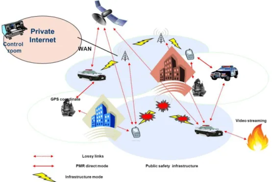
Figure 2.4: Partially destroyed public safety infrastructure.
We show in Figure 2.4 a typical example of a partially destroyed public safety infrastructure. In such situations, a number of access points can be demolished hence rendering a disconnected networks with inaccessible areas. Unfortunately, these inaccessible zones are the most affected areas by the catastrophe where rescuers will operate first requiring communication facilities. These teams interactions are not only intended to manage locally their activities but also to coordinate relief operations of different rescue teams in the control room C2. Besides, in these partially destroyed infrastructures, many lossy links (dashed arrows in Figure 2.4) are available. Such links are usually not exploited in traditional wireless networks since they present high error rates. Additionally, the more rescuers are deployed in the area, the more lossy links are available creating further diversity and routing paths to the operating infrastructure. Public safety operations usually take place in outdoor circumstances. However, rescuers will need to maintain communication also when entering indoor facilities such as factories, warehouses, or residential buildings, for example in order to carry out search and rescue operations. In this case, the communication channels between the rescue personnel and the control unit suffer from attenuations caused by heavy walls or floors instead of large distances. Furthermore, the movements of the personnel inside buildings will result in significant dynamic changes in the connectivity and the network topology.
2.1.3
Communication case
Following an important infrastructure collapse, a deployed public safety network presents relatively new and highly challenging communication characteristics. We detail herein few technical aspects observed in these types of networks.
Channel characteristics: PPDR deployments usually cover big areas with hundred meters of communication range. Indeed, a TETRA base station creates a cell of a radius that can reach one kilometre. This range can be extended with the relaying capability of public safety devices
(Direct Mode). Consequently, the communication medium is established between in line of sight nodes. Since the operating frequencies are assumed low and communication distance relatively high, the channel can be modelled as low capacity suffering from shadowing phenomenon. Note here that in an urban operation with a partially destroyed infrastructure, communication ranges tend to increase, favouring additional device to device information exchange thus lower distance device to device communications. It is also worth noting that in some particular cases, rescuers might operate in indoors conditions. This can have non negligible impact on the observed wireless environment as we describe further in this document.
Node density: Traditionally public safety scenarios are characterized by a reduced number of base stations. Indeed, this is a direct impact of using low frequencies and high transmission ranges. However, in partially destroyed networks in urban environment, exploiting device to device interactions shall increase node density thus changing completely the properties of the studied network. In such configurations allowing more than one hop relaying in the rescuers device becomes necessary. Therefore, going one step further than the actual public safety direct mode (DMO) that enables only a single hop extension from the base station needs to be considered in our scenario. Moreover, depending on the density of our deployments, a diversity of routes between two communicating nodes can be established. Exploring this route diversity can offer considerable advantages in such scenarios.
Node mobility: We consider a network topology with fixed communicating nodes. In fact, during a relief operation, it is assumed that rescuers do not move during their communication periods. In other words, this can be formalized as considering rescuers mobility timescale much greater than communication timescale. Note here that we do not consider in our scenario communication with mobile vehicles but only with deployed rescuers in the relief area. Vehicle to infrastructure and vehicle to vehicle communication patterns are considered in other use cases within this project.
Traffic pattern: Most of public safety operations rely on a point to multipoint communication scheme. Indeed, a major part of the information exchanged target essentially the whole group participating in the mission. More precisely, coordination orders from the control room are distributed to the whole rescue teams. Similarly, locally observed conditions observed by individual rescuers are shared with team members. This observation also applies to automatic positioning systems where coordinates of every single node are of an interest for everybody. In addition to the automatic person/vehicle location and push to talk services, new applications are emerging in the area of public safety. These applications have new constraints and additional requirements that need to be satisfied. We describe below the most relevant applications and quantify their quality of service (QoS) requirements.
Automatic Person/Vehicle Location (APL/AVL) distributes periodically the GPS coordinates of participating rescuers. This application has a point to multipoint traffic pattern. Since these messages are sent at a regular basis, losing an update from time to time is tolerated. Moreover, since the position is periodically refreshed transmitting a delayed APL message is not necessary. Therefore the APL service requires tuneable reliability and strict delivery delay threshold. In other words, if the intermediate node estimates that the location service update will not meet a decided deadline before reaching the destinations the updates can be locally dropped.
Push-to-talk is a half-duplex voice application that allows group communication between rescuers. This service requires strict delivery delays since many of the sent voice messages will generate instantaneous interaction between users. As for the loss rate, voice applications tolerate limited error rate because the human brain is able to decode the sent voice message even though part of the information is corrupted.
Short message service (SMS) is part of the new types of application emerging in public safety area. Clearly typing a message during a relief operation was long time considered as not feasible. Especially rescuers usually have special gloves resistant to fire, water and tough weather conditions. However, with the latest progress in voice and speech recognition area, it is becoming possible to write SMS by simply speaking to the device. Consequently, public safety operators are seriously studying the possibility of adding this feature in public safety devices. SMS as a service requires high reliability in the delivery process (0 error rate at the application layer) but can tolerate a delay of up to a few seconds.
mobile devices and the widespread of smartphones having very high computing and communicating capabilities is undoubtedly impacting the PPDR domain. Therefore, capturing real time videos and streaming them to rescue teams and even to command and control centre is very seriously envisaged. Such videos will allow better understanding of the situation, deciding whether deployed rescue teams are enough and planning how to coordinate the rescue efforts. In terms of quality of service, video streaming applications are tolerant to losses due to recent progress in video codecs. They can also compensate delays through buffering. However video streaming is very sensitive to jitter. Indeed, since the buffering period is fixed, any variation in the end to end to delay can cause buffer overflow or buffer starvation at the receiver.
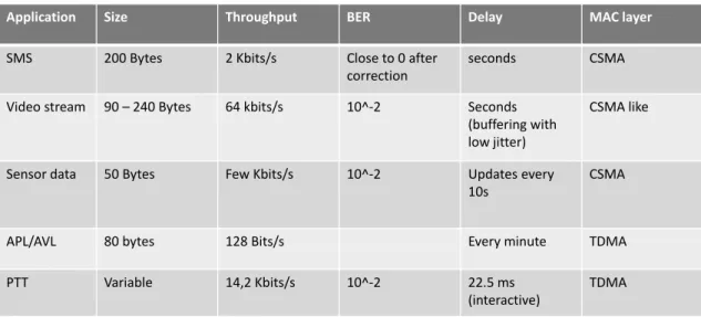
Table 2.4 below summarizes envisaged public applications with precise QoS requirements in a public safety deployment. The numbers have been collected from the ETSI TETRA standards, and specialized references in the public safety area (www.firstresponder.gov/TechnologyDocuments/Assessing Video Quality for Public Safety Video.pdf).
Table 2.4: QoS requirements for public safety applications.
Application Size Throughput BER Delay MAC layer
SMS 200 Bytes 2 Kbits/s Close to 0 after
correction
seconds CSMA
Video stream 90 – 240 Bytes 64 kbits/s 10^-2 Seconds
(buffering with low jitter)
CSMA like
Sensor data 50 Bytes Few Kbits/s 10^-2 Updates every
10s
CSMA
APL/AVL 80 bytes 128 Bits/s Every minute TDMA
PTT Variable 14,2 Kbits/s 10^-2 22.5 ms
(interactive)
TDMA
2.1.4
Wireless characteristics
In the public safety use case mobile network nodes are encouraged to create an ad-hoc network with a limited access to a working base station or other infrastructure. Due to dense deployment of rescuers and mobile devices in general, low distances between the nodes can be assumed and each node will only communicate with its close neighbors. Also a low quality channel can sometimes be assumed to reach remaining base stations. Mobile network nodes are either end devices of the rescuers working in the destroyed region or mobile base stations deployed stationary or on top of moving trucks. Due to high population density in industrial countries mostly the devastated regions have urban character with many buildings of varying height and streets of different widths, crowded with cars and trucks, traffic lights, and traffic signs.
The moving speed for rescuers that operate afoot can be safely assumed to be below 20 km/h. The mobile base stations in an urban area will also be assumed as deployed in fixed positions. Furthermore, in a densely deployed rescue area, the distance between the nodes is assumed to be below 100 m and the urban character of the region creates severe multipath echoes in the wireless channel with or without line-of-sight (LOS) connections between the nodes. Therefore the B1 and B2 channel models of the WINNER 2 project are considered for these scenarios. A typical channel impulse and frequency response of the tapped delay line model is shown in Figure 2.5. An overview of the underlying physical channel parameters is shown in Table 2.5. The contained values are calculated from the B1 (Urban micro-cell) and B2 (Bad urban micro-cell) channel models that were provided by the WINNER 2 project [WIN2D112] where an average node distance of 100m was considered. It is worth noting that the WINNER models apply to frequencies between 2 and 6 GHz, and thus should not be used for evaluation in the 700MHz band. In the RESCUE project, the focus is on carrier frequencies above 2 GHz.
Table 2.5: Physical parameters of the wireless channel.
WINNER B1 (LOS) WINNER B1 (NLOS) WINNER B2
Terminal Speed 0-70 km/h 0-70 km/h 0-70 km/h
Doppler Spread ~50 Hz ~50 Hz ~50 Hz
Coherence Time 17 ms 17 ms 17 ms
RMS Delay Spread 36 ns 76 ns 480 ns
Coherence Bandwidth 5 Mhz 2.6 MHz 417 kHz
Fading Model Rician and Rayleigh Rayleigh Rayleigh
Average pathloss 81dB 81 dB 81 dB
Shadowing Log-normal, σ=4.7dB Log-normal, σ=6 dB Log-normal, σ=6 dB
Figure 2.5 Typical channel impulse response of the wireless channel (WINNER B1-LOS) [WIN2D112].
An important part of the concept of the links-on-the-fly technology is the continuous change of the network topology and of the nodes available for communication. From a use case perspective this topology change is mainly coming from the mobility of the distinct nodes that are included in the network. As the rescuers move inside the relief region, LOS connections may or may not be blocked by occurring obstacles such as walls or cars. Furthermore, when rescuers enter an indoor environment, for example a burning house, at least LOS connection is lost, but also links may become unreliable or even drop completely because of the large pathloss or strong scattering. Here, the RESCUE approach will help to keep the communication stable by exploiting several routes in parallel.
Topology changes can also occur when the distance between nodes increases so that only a lossy link or even no link at all can be established. On the other hand, new links become available when two nodes come closer to each other. Additionally, in case of setting up or removing a mobile base station, several links are established or removed. A network topology change can also occur if the wireless resource that was used for one link is used by another, more important link so that the original link needs to be dropped. Essentially, every change in the quality of a node-to-node link can cause a severe topology change that needs to be recognized and handled by the ad-hoc network and the applied coding.
2.2
Vehicle-to-vehicle and group communication
Vehicular ad hoc networks (VANETs) are of paramount importance for providing safety-critical and commercial road services. In the last decade many research, standardization and development activities have been carried out in governmental, industrial and academic initiatives. These initiatives have created a solid technology basis that provides wireless communications among the vehicles and between vehicles and the road-side infrastructure. Here, the network is a combination of ad-hoc and infrastructure based subnets. In this network each vehicle can be treated as a specific node. Vehicle-to-Vehicle communications (V2V) promise to improve road safety and optimise road traffic through co-operative system application especially for emergency communication scenario analysed in the RESCUE project.
Figure 2.6: Typical VANET architecture with moving nodes.
In the United States the Federal Communication Commission (FCC) allocated 75 MHz of bandwidth in the 5 GHz spectrum to dedicated short-range communications (DSRC). The European Conference of Postal and Telecommunications Administrations (CEPT) allocated a 50 MHz bandwidth in Europe. The allocated spectrum covers multiple channels and is reserved for cooperative Intelligent Transportation Systems (ITS) with road safety, traffic efficiency and infotainment applications.
The vehicular environment has some unique characteristics, such as the variable and unstable nature of wireless links, the lack of central coordination, the short-lived intermittent connectivity and the dynamic topology that lead to a very challenging multichannel coordination, access and synchronisation. So, the efficient and effective usability of a multichannel architecture is a controversial subject. The communication is achieved by using single-radio or dual-radio transceivers. Single-radio transceivers operate on only one radio channel at a specific time in contrast to dual-radio transceivers that can operate on two radio channels simultaneously [CM13]. However, the expected deployment of vehicle-to-vehicle communication in the next years, starting in 2015, considers a basic system with a single-radio transceiver that operates on a common control channel.
Research and application development in VANETs are driven by an amendment to IEEE 802.11 (or ITS-G5 as the equivalent in Europe) to support the cooperative ITS applications, where reliability and low latency are crucial.
Table 2.6: Multichannel VANET standards: United States vs. Europe [CM13].
2.2.1
State of the art: standards for multichannel VANETs
The standardisation path for VANETs is very complex; a first release of standards has been published by the Institute of Electrical and Electronics Engineers (IEEE) [Ken11] and European Telecommunications Standard Institute (ETSI) [Fes11], however, standards are still under development. Recently a new protocol standard for vehicular communications has been introduced and adopted. In the US, the IEEE 1609 protocol stack known as Wireless Access in Vehicular Environment (WAVE) defines the protocols used for the DSRC as well as the specification for the technical requirements. The IEEE 1609 standard family covers several technical aspects and layers, such as multi-channel organisation, spectrum allocation, networking and transport protocols as well as access layer specifications, channel usage and applications’ requirements specifications. Figure 2.7 describes the protocol architecture developed by ETSI and IEEE, i.e. the protocol stack of the ITS Station and WAVE device [CM13].
Table 2.6 summarises the two set of standards, which have some common design choices, but they differ in other decisions, for instance, related to the number of service channels and networking protocols.
Europe United States
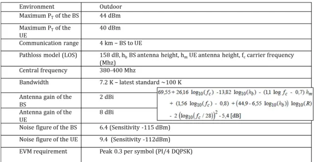
Environment Outdoor
(Highway, Urban, Suburban)
Same Maximum PT of the MT
(Mobile Terminal)
Usually 33 dBm but up to 44.8 dBm Same Central frequency (EU) ITS road safety: 5 875 MHz to 5 905 MHz
ITS non-safety applications: 5 855 MHz to 5 875 MHz
5.85–5.925 GHz
Bandwidth Total allocated spectrum: 50MHz
(30 MHz are reserved in the ITS-G5A band for road safety services,
20 MHz in the ITS-G5B band are for general-purpose ITS services (e.g., road efficiency, service announcements, multi-hopping) )
75 MHz
Channel 4 (CH172, CH174, CH176, CH178) 6 (CH172, CH174, CH176, CH180, CH182, CH184) Physical and MAC
layers
Multiple access technologies, among which ETSI ITS-G5, same as 802.11p
IEEE 802.11p, 1609.4
Higher layer ETSI ITS Station: Facilities, Networking and Transport, Security layers
IEEE 1609.0, 1609.2, 1609.3 Standard deviation shadowing 2.95 to 2.12 dB 4.49 to 3.55 dB
Figure 2.7: Left side: IEEE WAVE stack; Right Side: ETSI ITS station stack [CM13]. The network perspective of VANETs consists of the physical (PHY) layer, the medium access control (MAC) layer and the network layer with some lightweight transport layer functionality. The PHY and MAC layer is based on an amendment of the popular IEEE 802.11 standard, called Outside the Context of a BSS (OCB), which enables a simplified ad hoc mode without the exchange of control information. This standard was formerly known as IEEE 802.11p and was meanwhile integrated into the IEEE 802.11-2012 standard. The role of the MAC layer is to achieve reliable medium access control and to alleviate data traffic collisions. The network layer in the IEEE 1609 stack defines a single-hop network protocol with minimal packet header size, whereas the network layer in the ETSI stack supports both, the exchange of single-hop periodic messages and also multi-hop transfer of packets utilizing geographical addressing. Besides the two networking approaches, IEEE 1609.3 and ETSI EN 302 636, other protocols have been standardized, such as Optimized Link State Routing (OLSR). On top of the network and transport layer, application-specific messages for road safety and traffic efficiency applications have been defined – including the Basic Safety Message (BSM) in the US, and the Cooperative Awareness Message (CAM) and the Decentralised Environment Notification Message (DENM).
Figure 2.8: Classification of road safety applications (source: ETSI).
Applications for road safety are typically categorized according to the time-to-collision (TTC) (see Figure 2.8) and range from pure driver information to precrash applications. It is worth noting that the first release of standards from IEEE and ETSI cover the applications for information, in-vehicle signage, awareness and warning, but do not support applications with ultra-low latency requirements.
2.2.2
Situational model and network characteristics
The communication in VANET raises several challenges. End-to-end connectivity in this type of highly dynamic and unstable networks is difficult to achieve with traditional communication and networking techniques. Indeed, vehicular networks suffer from frequent disconnections and topology changes due to the arrival and exit of new vehicles in the system. Moreover, the link quality is highly dependent on the distance between vehicles and their respective speed, thus continuously changing in time. Figure 2.9 lists some characteristics and typical functionalities of VANETs. The dynamic and highly unpredictable variations motivate the need for a new generation of communication paradigms for VANET.