Japan Advanced Institute of Science and Technology
JAIST Repository
https://dspace.jaist.ac.jp/
Title
Exploring the performance of turbo MIMO
equalization in real field scenarios
Author(s)
Trautwein, Uwe; Matsumoto, Tad; Schneider,
Christian; Thoma, Reiner
Citation
The 5th International Symposium on Wireless
Personal Multimedia Communications, 2002., 2:
422-426
Issue Date
2002-10
Type
Conference Paper
Text version
publisher
URL
http://hdl.handle.net/10119/9124
Rights
Copyright (C) 2002 IEEE. Reprinted from The 5th
International Symposium on Wireless Personal
Multimedia Communications, 2002, 2, 422-426. This
material is posted here with permission of the
IEEE. Such permission of the IEEE does not in any
way imply IEEE endorsement of any of JAIST's
products or services. Internal or personal use of
this material is permitted. However, permission
to reprint/republish this material for
advertising or promotional purposes or for
creating new collective works for resale or
redistribution must be obtained from the IEEE by
writing to [email protected]. By choosing
to view this document, you agree to all
provisions of the copyright laws protecting it.
Description
Exploring the Performance
off
Turbo MlMO
Equalization in Real Field Scenarios*
Uwe Trautwein
Tad Matsumoto
Christian Schneider
Reiner Thoma
Tewisoft GmbH University of Oulu Ilmenau University of Technology
Ilmenau, Germany Oulu, Finland Ilmenau, Germany
uwe.trautwein @ tewisoft.de tadashi.matsumoto @ee.oulu.fi tho @e-technik.tu-ilmenau.de Abstract
This paper describes the methodology and the results of pelformance investigations of the Turbo MIMO equalizer concept for broadband MIMO systems. Direrent applica- tion setups are introduced and realistic simulations based on measured propagation data are described. Relationships between the propagation characteristics, the antenna con- jigurations, and the achievable bit error rates are shown. Although in many of the considered constellations Turbo MIMO detection appears feasible in real field scenarios, there exist cases with poor pelformance as well, indicating that for practical applications a technique for link adapta- tion of the transmitter and receiver processing to the envi- ronment is necessary.
Keywords
MIMO systems, multipath channels, Turbo detection, link level simulation, space-time processing
INTRODUCTION
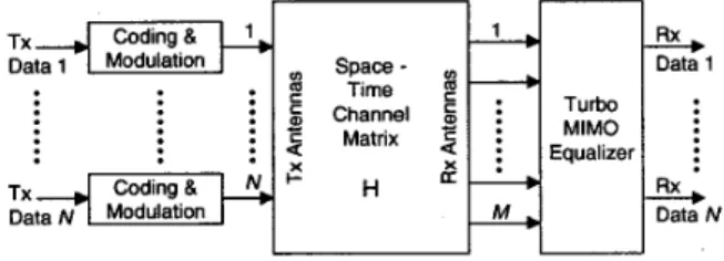
Recently, the use of multiple antennas at both transmitter (Tx) and receiver (Rx) sides of a mobile communication link has attracted much attention in the research. The reason for this is the expected large gain in channel capacity (bits/s/Hz) compared with traditional systems. This is achieved by split- ting up the transmit data stream into N multiple substreams, each of which is transmitted via a different antenna at the same time- and frequency-slots and without other means of orthogonalization. The receiver must separate this mixture of signals solely by using multiple receive antennas (Fig. 1).
Its ability to do this strongly depends on the radio channel characteristics. The general requirement is that for each of the transmit signals a specific signature arises over the aper- ture of the receive antenna array, which is potentially an
effect of the different spatial locations (and/or orientations /
polarizations) of the transmit antennas.
Many of the proposals for implementing MIMO systems con- sider only algorithms suitable for frequency flat fading radio channels. A straightforward extension of these algorithms to broadband single carrier systems would mostly result in an unacceptable numerical complexity. A promising pro- posal for a numerically efficient signal separation method for frequency selective channels combines the concepts of soft interference cancellation and soft-input / soft-output (SISO) *This research was conducted jointly with other authors when Dr. Mat- sumoto was with N l T DoCoMo, Japan. It has been approved by DoCoMo's administration that this paper is to be presented at the WPMC'02 confer- ence.
channel decoding in an iterative Turbo detection scheme
[-'.I,
which will be called a Turbo MIMO equalizer (TME). Re- ceivers of this type depend on the spatial radio channel struc- ture at the transmitter side as well as the receiver side and the delay structure. Hence, evaluating the performance of MIMO detection schemes by means of simulations requires much more detailed knowledge and exactness of the channel structure than conventional single antenna systems or sys- tems with multiple antennas only at one side of the link. That is the reason why it is proposed to use the results of double-directional channel sounding experiments [ 3, 31 for MIMO link level simulations.TxlFJ
Data 1 Modulationf-
{i
T u b ~~t~ N Modulation M Data N MlMO _m Channel.
2
Matrix ~ Equalizer Tx Codiig8'
Rx I I UFigure 1. System model for MlMO transmission First, this paper presents a brief summary of the basic oper- ation of the TME concept. Next, the MIMO measurement procedure and some aspects of measurement based link level simulations are described. Bit error rate (BER) curves show the TME's performance in different application scenarios and antenna configurations for the case of a channel ideally known for the receiver. A separate section indicates the in- fluence of a realistic channel estimation scheme on the BER performance.
TURBO MIMO EQUALIZATION
The TME concept has been adapted from a proposal of an iterative CDMA receiver [ 11. The transmitter of aTME based system (Fig. 1) performs independent encoding of a number N of independent data streams by a simple convolutional error correcting code, interleaving, and modulation, yielding the coded transmit data symbols bn(l). BPSK modulation is assumed for simplicity. The radio channel between each pair of the M receive and N transmit antennas is modeled by the complex finite channel impulse response hmn(Z) having L taps. Thus, the receive signal at antenna m can be written as
L-1 N
T m ( k ) = hmn(Z)bn(k - 1 )
+
G.m(k), (1)2,
(4
bits are approximated by assuming a Gaussian distribution of the MSE, as proposed in [ I],I
SISO
,m
Decoder
y-
1
I..
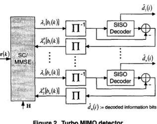
d , ( i ) :=decoded information bits Figure 2. Turbo MIMO detector
where v m ( k ) is complex additive white Gaussian noise with
variance 1. For the detection process, the receiver uses a number of spatial and temporal receive signal samples which are stacked into one large space-time (ST) receive signal vec- tor for notational convenience, r(k) = [ q ( k )
.
. .
T M ( ~ ). . .
T I ( k+
L
- 1). .
T M(IC
+
L
-
1)lT. A compact matrix no- tation of ( I ) can be written in the form(2) by introducing the ST MIMO channel matrix H and proper arrangement of coded symbols and noise samples in vectors, similar to [ 2 ] . Additionally, the vectors h, are defined as
T
which are essentially the central N columns of the H matrix.
A simplified diagram of the Turbo MIMO equalizer is shown in Fig. 2. In a first step, the log likelihood ratio (LLR) A; [b,(k)] delivered by the SISO channel decoding in the previous iteration (p) is used to compute a soft replica of the coded transmit data symbols, 6,(k) = tanh ($A; [b,(k)]).
This allows a soft cancellation (SC) of intersymbol (ISI) and multiple access interference (MAI) components in the received signal vector, which is to be performed for each substream n,
(3) The vector
L,
( k ) comprises all soft symbol replicas, exceptfor the symbol of interest 6,(k), which is set to zero. After the SC step, remaining IS1 and MA1 components are mini- mized by applying an instantaneous MMSE filter wn(k) on theoutputofeachoftheNcancelers, zn(k) = w:(k)r,(k).
This is especially important for the first iteration, where the cancelation process is without effect due to the unavailability of apriori information. The solution to the MMSE optimiza- tion is shown to be
(4)
Here, I is the identity matrix of size
( L M )
and the matrix A,(k) is a diagonal matrix containing the expected values of the remaining MA1 and IS1 components after interference cancelation. Thus, it can be derived from the vector of the estimated soft bits. The LLR's A1 [b, ( k ) ] of the detected coder(k) = Hb(k)
+
e v v ( k ) ,h, = [hi,(O)...h~,(O)...hl,(L-
l)***hl,(L-
l)] ,rn(k) = r(k) - HE,(k).
wn(k) = [HA,(k)HH
+
C T ~ ] - ' h,.The more iterations are performed, the more reliable are the estimated coded data symbols 6,(k). Thereby, the SC step
becomes more perfect, and the smaller is the role of the ST MMSE filter for interference supression. At this stage, its role is to combine the multipath components within the filter's delay coverage. In contrast, for the very first iteration, it is the only means for separating the multiple co-channel signals. It is known that linear ST processing is capable to exploit multipath diversity if a sufficient number of antennas is available to allow spatio-temporal selectivity
[?I.
MEASUREMENT BASED SIMULATIONS
The reliability of the results of link level simulations strongly depends on the use of a proper approach to the modeling of effects of the radio propagation. The required level of detail and the necessary classification of propagation environments for defining accurate statistical channel models increases sig- nificantly if systems with a single antenna at both ends of a link are extended to systems with multiple antennas at one end of the link, and moreover extended to MIMO systems. The reason is that the latter systems rely more and more on the spatial characteristics of the wave propagation. Conse- quently, new receiver concepts should always be verified by using channel measurements in appropriate real field sce- narios. Broadband real-time channel sounder devices sup- porting multiple antennas 131, such as the RUSK MIMO from MEDAV [C;], are required for the measurements. Items (i) - (iv) summarize some important aspects for performing MIMO measurements and using the measurement data in transmission system simulations.
(i) The measurement setup should resemble a potential sys- tem application setup. In this paper two major application setups are differentiated. The first setup is called the point-to- point (P2P) setup, where the distances between the antenna elements at the Tx as well as at the
Rx
are on the order of some wavelengths. The main goal of this application is to reach a high capacity for a single radio link, e.g., in a wire- less LAN. The other application setup is called the multiuser (MU) setup. This case applies the MIMO approach to a cel- lular system for establishing a space division multiple access among different users, each user terminal equipped with a single antenna. Thus it is a means to maximize the cellular system capacity. Obviously, the transmit antenna spacing is significantly larger than in the P2P setup.(ii) Careful selection of the measurement antennas is neces-
sary, depending on different aspects under investigation and the desired approach for channel simulation. The straight- forward approach computes the channel coefficients hmn(Z)
directly from the measured impulse responses. A simple pre- processing handles the setting of the desired bandwidth and the reduction of the measured impulse response length to the effective delay window. Although this approach is consid- ered to be reliable in all cases, it lacks flexibility, because the
characteristics of the measurement antennas is always part of the simulated system. Hence, antenna array geometry and element beam pattern of the measurement device must be suitable for a potential system application. Not every measurement antenna meets this requirement, because they are mainly designed to achieve a high resolution for spatial propagation parameter estimation. This is in turn the pre- requisite for the very flexible method of measurement based parametric channel modeling (MBPCM)
['!I.
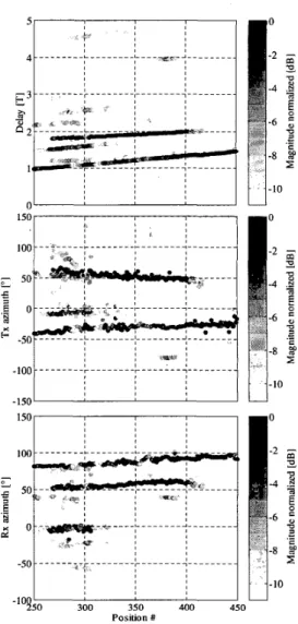
An example of the analysis step of this method is given in Fig. 3 showing a cutout of a measurement drive along a street where line- of-sight between Tx and Rx was frequently obstructed by parking cars. Since these parameters together with the phase of each multipath component describe the wave field around the Tx as well as theRx
antenna arrays, they can be used to make a synthesis of M M O impulse responses for different antenna array shapes than that of the measurement arrays. Even a variation of the array position in a small surrounding or a change of the orientation is possible. Assuming plane wave-fronts and only azimuthal resolution, the synthesis canbe performed by using
L,
(1) = aR, ( + R p , E m ) ,where P is the number of multipath components, "iP is the complex path weight of path p with delay rp, g ( t ) is the continuous time impulse response of the combined transmit and receive filters, and a ~ , , is the nth element of the transmit array response vector for the azimuth of departure +T,. It depends on the space vector I:
,
from the center of the mea- surement array to the location of antenna n. For the receiver side, the array response is similarly comprised in UR,. It should be noted that the array response may also contain a non-homogenous directional element characteristics. (iii) The result of link level simulations are usually mean BER's averaged over a certain number of statistical realiza- tions of the radio channel. When measured channel data is used for simulation, a careful analysis of the measured data is necessary for the result evaluation. Averaging over channels which are too different must be avoided. Here, the para- metric analysis as already introduced above is very valuable, since it can be recognized from Fig. 3 that even within only a few meters the propagation conditions can change dramat- ically. Furthermore it enables to make a matching between the physical propagation conditions and the performance of a certain receiver configuration.(iv) The use of measured channel data requires implement- ing some basic real-world receiver functions. Since the mea- sured impulse responses have usually a significantly longer duration than the temporal memory length of the receivers, the delay control must ensure, that the receiver processing is temporally synchronized to that portion of the impulse responses offering the optimum performance. The power control is responsible for adjusting the desired receiver sig- nal to noise ratio ( S N R ) . For the MU setup, an ideal power control adjusts the transmit power of each transmitter such that the mean received power over all elements is identi-
P
TP 9 ( 1 ~ - ~ pUT, (+Tp ) E
p = 1
-"?50 300 340 460 450
Position #
Figure 3. Estimated propagation parameters ,along a street (delay normalized to 1/T = 12 Msym/s, magnitudes smaller than -10 dB are plotted with -10 dB)
cal for all users,
E:=,
P,, = M / N . While this holdsconstant the total transmit power independently of the num- ber of users, the total received power increases with the number of receive antennas. This practical treatment as- sumes that the receive array is placed into a wave field of a given strength, evoked by the transmitted signal energy. For the P2P setup a modified power control scheme with lower complexity seems attractive, which adjusts the total received mean power while transmitting identical powers by each an- tenna,
E:=, E:=,
P,, = M . Without showing results itshould be mentioned, that this scheme introduces partially a serious performance degradation of the TME based system. SIMULATION RESULTS
This section presents several simulation results for TME based systems operating at 12 Msymbols/s per Tx antenna. The results for 24 Msymbolds indicate nearly identical per- formances as long as the number of temporal receiver taps is
SNR [dB]
Figure 4. iteration gain of a 2/2 TME in the Tokyo scenario, L=10
MU
4 ;
2 3 4 ; 6 ; 8 9 l oSNR [dB]
Figure 5. BER curves of a 4/4 TME in the Tokyo P2P scenario for different antenna spacings
properly increased. All measurements have been performed at 5.2 GHz carrier frequency. Fig. 1 illustrates the iteration gain of the receiver for a MU scenario measured in the down- town of Tokyo with 2 Tx and 2 Rx antennas (2/2 TME). Due to the long delay spread in this environment, the channel im- pulse responses are modeled using 38 delay taps, while for complexity reasons the receiver itself is only equipped with L = 10 temporal taps. The delay control is responsible for optimum delay window selection as explained above. The
BER
curves obtained for this scenario are very similar to that using a synthetic L-path independent Rayleigh fading channel model, with only a slight degradation of about 1 dB. Another simulation in the same environment assumes a P2P setup with 4 Tx and 4 Rx antennas and L = 5. The BER curves in Fig. 5 are depicted for different Tx andRx
element spacings after 4 iterations. In this scenario it is equally important to have a larger element spacing at the Tx as well as the Rx side of the link.Whereas in the presented Tokyo scenario the R M S azimuth spread at the Rx side is in the order of 30", significantly lower values have been observed in a suburban residential area in Ilmenau. These values are shown as the solid curve in Fig. 6 while moving the transmitter along a route of about 120 m.
10 ' 30.3 'D
P
@, l o 2 205=
&8
m 0 4 m 6 WJ E 10 1 0 n:lo4 1000 2000 3000 4ooo 5000 6OOo 7000 0
Position #
Figure 6. Rx azimuth spread and BER of a 3/3 TME in the limenau P2P scenario
IO0
0 1 2 3 4 5 6 7 8
SNR [dB]
1 o4
Figure 7. BER curves for different Rx antenna spacings of a 414 TME
The light bars in the background of the figure indicate the BER of a P2P 3/3 TME at a constant S N R of 10 dB. In the areas with a low azimuth spread, the receiver frequently shows a large BER or complete failure despite of the high SNR.
In producing the next two figures, the MBPCM method has been applied. For a small section of the data shown in Fig. 3, where a significant path exists at 4 T, the impulse responses for 4 element uniform circular Tx and Rx arrays of different element distances and array orientations have been computed. Since the Rx azimuth spread is only at the order of 30", a larger element spacing d leads to improved performance (Fig. 7) at a fixed Tx element distance of 1X.
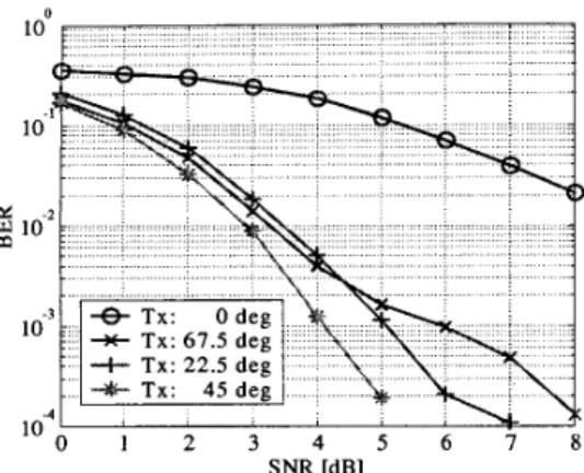
A similar clear relationship could not be found for the oppo- site case of varying the Tx element distance at constant Rx element distance, probably due to the higher azimuth spread of about 50". The results of this experiment are similar to those depicted in Fig. 8, where the Tx array with 1X element spacing has been turned to 4 different orientations: Some of the constellations yield a very similar performance and one shows a dramatic degradation. The reasons for this behavior could not yet completely cleared up, but a likely explanation is that the multipath diversity in this scenario is not large enough to compensate spatial fading effects in any situation.
10
++ Tx: 67.5 dec
0 1 2 3 4 5 6 7 8
SNR [dB]
Figure 8. BER curves for different Tx antenna orienta- tions of a 4/4 TME
CHANNEL ESTIMATION
All previously presented simulation results assumed that the ST channel matrix H is ideally known to the receiver. A real receiver must perform the channel estimation before it can start the detection. Estimation errors will introduce an additional performance degradation which has been investi- gated by simulating a realistic channel estimation scheme, that relies on the transmission of training symbols in all Tx channels simultaneously at the beginning of a data burst. The estimator jointly estimates the vector of impulse responses from all N transmit antennas to one receive antenna h - corresponding MMSE optimization criterion is given by
[h,l(L - 1) * e . h,N(L
-
1). * * h,l(O). * . hmAr(0)]TA
h, = argrnin E
{
Ilr,(k) - h:b’(k)1l2},
(6)h m , € C N L
where
b’(lc)
consists of the firstN L
elements of the vectorb(k) introduced in (7). During the training phase of a burst the b’(k) are known to the receiver. An adaptive solution of the optimization problem has been implemented by using the recursive least squares (IUS) algorithm. Fig. 9 compares the BER performance that can be achieved for a 2/2 MIMO system in a MU scenario with an ideally known channel
(LT
0) with that of a system using channel estimation based on 64 training symbols (LT: 64). Additionally, different numbers of temporal taps of the receiver are considered. The curves for the case of a known channel show a small advantage for receivers with a larger number of temporal taps. This situation is reversed for the curves including channel estimation, since the remaining estimation error depends on the ratio of the numbers ofIUS
iteration to the numbers of temporal taps, which varies between 12 for L = 5 and 5.5 for L = 10. Since the required number of training symbols is relatively large, the proposal of [ 21 for performing iterative channel estimation has also been applied successfully to real field data. For that purpose, additional reference data are obtained at higher iterations by using reliably detected data symbols as additional reference data. This scheme permits reducing the number of transmitted training symbols at the price of a higher number of Turbo iterations.3
m*
L 8, LT:64+
L 10,LT:64 -ff- L 8, LT:O 1-63- L 10,LT:OI
1 2 3 4 5 6 7 8 SNR [dB]Figure 9. Influence of the channel estimation on the per- formance of a 2/2 MIMO system
CONCLUSIONS
MIMO communication systems exploit the spatial radio chan- nel characteristics in new ways, requiring a more detailed channel modeling approach for performance evaluations. Double-directional propagation measurements and careful analysis are therefore of essential importance. Two different methods for measurement based MIMO channel modeling have been presented and some practical consequences have been discussed. The TME concept for broadband single carrier transmission has been shown to yield reasonable per- formance in many real field scenarios. Especially in the P2P application setup, critical constellations may occur that un- derlines the sensitivity to the propagation conditions even at high SNR. Further investigations are needed for clarification. The observed results suggest that advanced link adaptation algorithms are required to prevent excessive BER’s. ACKNOWLEDGMENTS
The authors appreciate the supporters of this work, MEDAV GmhH, Ger-
many, for providing their MLMO channel sounder, N l T DoCoMo Inc., Japan, for initiating this research and for financial funding, and the col- leagues at llmenau University of Technology for performing the measure- ments and supporting the data analysis.
REFERENCES
[l] X. Wang and H. V. Poor, “Iterative (Turbo) Soft Interference Cancella- tion and Decoding for Coded CDMA,” IEEE Trans. Cornrnun., Vol. 47,
pp. 104&1061, July 1999.
[2] T. Abe and T. Matsumoto, “Space-Time Turbo Equalization and Sym-
bol Detection in Frequency Selective MIMO Channels,” IEEE Vehicu- lar Technology Con$, Atlantic City, NJ, Oct. 2001.
131 R. S. Thoma, D. Hampicke, A. Richter, G . Sommerkom, U. Trautwein, “MIMO Vector Channel Sounder Measurement for Smart Antenna Sys-
tem Evaluation,” European Tram. on Telecomrn., ETT Vol. 12, No. 5, Sep./Oct. 2001.
[4] R. S . Thoma, D. Hampicke, M. Landmann, G. Sommerkom, A.
Richter, “MIMO Measurement for Double-Directional Channel Mod- elling,” IEE Technical Seminar on MIMO Communication Systems,
London, Dec. 2001.
[5] U. Trautwein, D. Hampicke, G . Sommerkorn, and R. S . Thoma, “Per-
formance of Space-Time Processing for ISI- and CCI-Suppression in Industrial Scenarios,” IEEE Vehicular Technology Con$, Tokyo, Japan, May 2000.