低レイノルズ数における多数平行円柱格子の抵抗 (英文)
25
0
0
全文
(2) Vol. 10, No. 1 Journal of Hokkaido Gakugei University July, 1959. The Drag of Latdce of Many Parallel Circular Cylinders at Low Reynolds Number. Takashi SAWADA Department of Physics, Asahigazva College, Hokkaido Galcuge'i University, Asahigawa, Hokkaido, Japan. W^±: -f? ^ •< ^ ^^^{cfe^ ^^M^frnft^-?-®®^. The relations between the drag coefficient C of lattice of many parallel circular cylinders and Reynolds number R were studied experimentally. The drag of the specimen falling in a tower was measured in the region of -R=ca 0.25 ~ 1.0. If C vs R curve of a cylinder by Wieselsberger is used as standard, C vs -R relations of lattice are approximately the same as Wieselsberger's, when /i/d=250 and. 125, with d being the diameter of the cylinder, and h the distance of the centers of the two cylinders. Accordingly it is seen that Imai's formula on the basis of the combination of Stakes' and Oseen's approximations is better than Tomotika and Aoi's formula on the basis of Oseen's. The C vs -R relations of lattice, when1/i/d=50, 25 and 12.5, are somewhat similar to Fujikawa's C vs R curves of two parallel cylinders. The author has recently presented the paper of the same title to the Physical Society of Japan and it will be soon printed in its Journal. In this paper the same work is explained in detail.. 1. Introduction In nature we can see some hairy bodies such as pappi of dandelion or thistle. Formerly. the properties of drag of these bodies falling in air were studied by the author^. The pappi are assemblages of many thin cylinders in spatial configuration, so the hydrodynamical ana-. lysis of their drag should by very complicated. But the simplest of them may be subjected to theoretical analysis. Some years ago, H. Fujikawa2) calculated the drag of two parallel circular cylinders on the basis of Oseen's approximation. The drag of lattice of infinitely many parallel circular cylinders was studied by K. Tamada and H. Fujikawa3) on the same basis, and by T. Miyagi'° on the basis of Stakes'. In this paper the author presents the. results of experimental study on the drag of lattice of many parallel circular cylinders of finite length arranged in a plane. Further, he can determine the most credible curve of. drag coefficient C vs Reynolds number R relation of an isolated cylinder at low Reynolds number.. § 2. Specimens and Experimental Method To make specimens of lattice of parallel cylinders, the author used thin glass filaments of ca 20 /.< in diameter. They were measured by the optical microscope with the dissolving power of 0.2 /; and therefore the accuracy of measurement was not so good with regard to each one filament, but the mean value of many may fairly accurate. First the author divided the glass filaments into the five groups as 21, 20.5, 20, 19.5 and 19 /<, and used them mixing so as to be 20/< in the mean value of diameter of filaments. The diameter of the filaments is nearly uniform along their axes, so the measurement of diameter was sufficient only at — 10 —.
(3) The Drag of Lattice of Many Parallel Circular Cylinders at Low Reynolds Number one section of a filament. If the number of filaments n is 10, and the residual of each filament Vi is 0.25 /<, then the probable error ro of the arithmetical mean value is calculated. by the formula ^=0.6745,,—sv n(n n{n—l) as 0,056,,. This is only 0.3% of the mean value of the diameter of the filaments. To set the specimen, a square-shaped framework made of glass filaments of 30~70/^ in diameter was used, the length of its one side being 6cm. The drag of the specimen was calculated from its final falling velocity in a tower of square cross section whose height and side are respectively 4.20 cm and 50 cm, The effective length of the tower to measure velocity. is 250 cm and the falling time was measured carefully by a stop watch with a 1/20 second scale. Because the plane of specimen must be kept horizontally in falling, at each corner of the framework was attached a filament of 8,0cm in length and 30~70^ in diameter, and their opposite ends were joined together at one point. This part is called "legs". In some specimens the length of legs are less than 8.0 cm. But the discussion on this will be seen. 0. 0. later. Furthermore, to protect the thin filaments of lattice, 1~3 supporting fflaments are attached perpendicular to them. The distances between centers of adjacent filaments, h, were varied as 5.0, 2.5, 2.0, 1.5, 1.0, 0.5 and 0.25. mm, See Fig. 1. As the diamenter of filament, d, is 20/<, the ratios hid are respectively. 250, 125, 100, 75, 50, 25 and 12.5. The coefficient of viscosity of air was calculated by Sutherland's formula: ^ ---'^. 0. T \^' C+To Tn. C+T. -50°C. where Vo= 1.722.10-4 poise, .To-273.150K and C= 105.6°K. The examples of the values calculated by the above formula are shown on the right side.. 0 20 40. 1) 1.465- 10-* poise 1.722. 1.819 1.912. These are the same as the values given in Kohlrausch's Praktische Physik (1955). The calculated V vs H curve is shown in Fig. 2. The density of air was calculated taking into consideration its humidity.. § 3. Determination of Standard C vs R Curves of Isolated Cylinder Set Perpendicular or Oblique to Uniform Flow If the drag of the framework, legs and supporting filaments is subtracted from the total drag of the specimen, then we can obtain the drag of lattice, from which we can find the mean drag coefficient of each cylinder per unit length. The drag of the framework and supporting filaments is calculated by means of the drag. coefl&cient of a circular cylinder perpendicular to uniform flow. In our experiments, the Reynolds number used in the above calculation lies between ca 0.3 and 3.0. In this region, C vs R relations are given by several authors. S. Tomotika and T. Aoi5) gave theoretical formula according to Oseen's approximation, and I. Imai!o by suitable combination of Oseen's and Stakes' approximations. See Fig. 3.. According to Tomotika and Aoi the drag coefficient of a circular cylinder is given as — 11 —.
(4) Takashi Sawada. ^.1C. ^. 1.9. T. 7. ,/. y 7. /. z. 7. ^. 1.7. ^. z. 7. T. T. _z_. 1.6. ^ T. z. 7. T. ^. 1.5. ^. ^. 7. f. T. -50 • -40 -30 -20-10 0 10 20 30 40 °C Fig. 2. CoefRcient of viscosity of dry air.. T+. 16 T^-i~2. D. where R==dv/i^, T -= log (8/R) — r, and r== 0.5772 ••• is Euler's constant. In Fig. 3 there is shown also the curve by Lamb7) on the basis of Oseen's approximation. It is. c=. STT. (2:. R ('o^-i. which coincides with Eq. (1) at R<1. By Imai's theory the inner solution of Stakes' approximation in the neighboring region of a cylinder should be matched with the solution of Oseen's approximation in the outer region at the boundary of the two regions. C and R are respectively expressed in the formula: 87T. R{ \oga. (3) 4fl4 - 12 -.
(5) The Drag of Lattice of Many Parallel Circular Cylinders at Low Reynolds Number. u 0). 0. LAMB (OSEEN APPROX.). 0. •TOMOTIKA-AOI, SIDRAK. (OSEEN APPROX.) •IMAI (LOW REYNOLDS NUMBER). IIMAI (HIGH REYNOLDS NUMBER) 2. 0. log R. 3.. Fig. 3. C vs R curves of a circular cylinder by Imai, Tomotika-Aoi, and Lamb.. IQa3. 4). R^^-vf where a is parameter, for example: a. R. c. The drag coefficient of a circular cylinder at high Reynolds number is given as. 2. 14.22. 3.85. 5. 3.47. 5.32. 10. 1.63. 7.50. according to Imai's general theory of bluff body,. 40. 0.401. 18.25. where C» is the drag coefficient for R->oo. Fur-. 0.1600. 36.06. ther k is a constant to be determined experimen-. 100. Cli2^C^/2+kR-1'2 (5). tally or theoretically. If we assume that Eq. (5) is correct for /?=40, then we can determine the value of k by use of Kawaguti's elaborate numerical computation8'1. He obtained C -= 1.6177 ior R =- 40 According to Brodestsky9'1. (6. C^-= 0.568 ,^ =0.500. Thus, the drag coefficient of a circular cylinder for high Reynolds number is given by C- (0.7071 + 3.572 R-1'2)2 (7) The curves of Eq. (3) vs (4) and Eq. (7) are shown in Fig. 3, where three small circles reprsent the numerical sulutions, i. e, values for /?—40 by Kawaguti and for jR—10 & 20 by Thomlo). — 13 -.
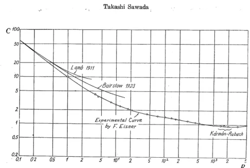
(6) Takashi Sawada. ^'xpe.rimenta.l Curve. by F. Eisner. 0.1 02 0.5 Fig. 4. C vs i? curves of a circular cylinder by Eisner, Lamb and Bairstow. 100 80 60 <t0. 20 co 8 6. ^\. 0. \. B 0. \. (D 8. ^. 0. ^. &. 4.. 1. ly^ / chiir. 6y. )/. s^ '] ?/. •> /. e. Ts t OL '(. y. s. '05-. 1 3 0. 0. 9. 0 0 0>. ~) at a.. o/ Wn. iry by. B-SOT. o.a. mm]. >=1. -off). axMteo3-0. eLsberger. Lamb S-fc.. s. 0.6. OA 0.2. 10-12 ^81002 '6810-'2 '68W22 "6QW^ "e8w^2 '6Bw^2 ^68io5. Fig. 5. C vs R curves of a circular cylinder by Wieselsberger.. ^?. Further F. Eisner10 and C. Wieselsberger1 ) gave respectively semi-emperical curves. The former is shown in Fig. 4 and the latter in Fig. 5, where the curve separates into two in the region of jR=4~400. The upper curve was obtained from Schlichting's GrenzschichtTheoriel3) and the lower from Wieselsberger's original paper. The author cannot understand the reason of this deviation. Perhaps Schlichting's curve may be uncorrect. Although the author could not see the original paper, he used Schlichting's curve, assuming it to be correct. But the region of the Reynolds number used in this work lies between ca 0.3 and 3.0, so the errors caused by this deviation are very small. Lately H. Finn10 reported numerous experimental data, in which are to our regret. — 14 —.
(7) The Drag of Lattice of Many Parallel Circular Cylinders at Low Reynolds Number. Ca. 0 DATA OF FINN + DATA OF WtESELSBER&ER. log 8. 10-2. 5 610-' 2 5 8 10 0 2 5 8 10'. 58 ,,2. Fig. 6. C vs R curve of a circular cylinder by Finn.. considerable fluctuations. See Fig. 6. But these curves are different from each other as seen in Fig, 7, so we can not decide. definitely which of them is the best. Therefore the author determined the most suitable curve by the method of trial and error. It is as follows:. In case of large value of h/d>125, the interference of each cylinder of lattice may be negligibly small. Let us assume any curve of the above as standard, and by means of a. suitable method which will be shown, determine C vs R curve of a cylinder set oblique to the main flow. Next we calculate the drag of framework, supporting filaments and legs,. then subtract them from the total drag of the specimen. Finally we obtain the C vs R curve of the lattice. If the latter coincides approximately with the assumed C vs R curve of a cylinder set perpendicular to the main flow, we can say that the assumed C vs R curve is true.. But concerning the above method, there may be some questions. The framework, supporting filaments, legs and lattice have singular points such as corners, edges and joints. Even if there are not any interferences in the lattice, we cannot neglect the above singulari-. ties, so there may be opinions that the drag should not be compared with the C vs R relation of an infinitely long cylinder. We cannot deny this opinion, but each filament of the specimen is very long compared with its diameter, so for practical purposes it can be treated neglecting the end effects. Later we will discuss again this problem, but at the present let us proceed along the above mentioned method. As shown later, it resulted that C vs R curves in the region 0.3<R<3.0 by Eisner,. Wieselsberger or Imai are better than that by Tomotika and Aio or Finn, but the value of drag coefficient by Imai in the region R<1 is slightly less than reality. But the difference between Wieselsberger's and Eisner's curves is small in this region, so the author could not -- 15 —.
(8) gw. ^< '<^ ~ 7~om o tiKa. &. Aoi s-y-. 02. ^p. s3.. &. 1. 0/f. Q2. a4 °6 Q812—4 ' 6 'Q'10 —^ Kg. 7. Comparison of C v.fi curves of a circular cylinder by several authors.. 40 60, 80 100. R.
(9) The Drag of Lattice of Many Parallel Circular Cylinders at Low Reynolds Number determine which of them is the better. In the present work, he adopfced temporarily Wieselsberger's curve as standard and could obtain satisfactory results.. The force acting on a cylinder set obliquely in a uniform flow has been studied by Tomotika, Aoi and Yosinobul5) on the basis of Oseen's approximation. Let us represent the transverse and longitudinal components as N=112-Pv2dC^. (8). L-=l/2-ftv2dC^. (9). here P is the density of fluid, v the velocity of the uniform flow, and C,v and Cz are non-dimensional force coefficients. Then the. resultant drag on unit length of the cylinder in the direction of uniform flow is given by. (10). D-= 1/2 • P v2d sin i (C,v+ Cj. cot i). w. here i is the angle of incidence, i. e. the angle between the axis of the cylinder and the direction of the uniform flow. See Fig. 8. In our experiment, the angle of incidence is determined by the length of the leg of the specimen. Because the. effective length of the leg shall be the true True length of leg. Angle of incidence. 8.0cm. 33°. 7.0. 38.5. 6.0. 47. length minus 0.1 cm of a superimposed part at the center for each leg, the angle of incidence of the leg is shown on the left side. In Fig. 9 the values of C==(C,v+Cz cot i) are given against Reynolds number.. First we experimented on the specimens constructed of framework and legs only. As stated above, the drag of framework was calculafced according to Wieselsberger's curve^ and was subtracted from the total drag. Then we obtain the drag coefficient of the leg, here. the projected length of legs is taken as 17,2 cm. Because of difficulty in obtaining the exact values of mass and dimension of specimen, the number of data is only three. Before we enter into the experimental data, some symbols are defined as follows: Do -— mg total drag of specimen. / length of cylinder suffix 1 framework 2 legs The data of the above measurement are shown below. 1) Specimen No. IV-6 d, = 2.00 • 10-3 cm. /i -= 25.55 cm. d, - 2,00 ". /, -= 32.2. D, = 0.608 dyn. v -= 20.42 cm • see"1. R, = 0.294. C, - 25.5. A - 0.343. R, - 0.294. C, - 29.36. D, -= 0.265. The curve shown in Fig. 10 is slightly different from the original in Fig. 7 at exact valuation, but this has any important meaning for the present and the author will proceed assuming that the curve of Fig. 10 is standard.. — 17.
(10) Takashi Sawada. •N. 102. <<•(. s. X. ?; n2l ^\. ^s. 6. 4 3. 2. -XJ. ^. \. x. ^.. 2CL/sln2i^. ^ ^. \ ^. s^ ^. 47^. ^. \. sj. ~\. ^^\. sj •^,. 10<. 8.5'. ^^ "XT. 33°. ^J. ^^ "^. S~J. Ss.. -s,. ^\. ^^. <s. ~s ~\. 6. 4 3 2 10°. '\. \. •\ ~~..
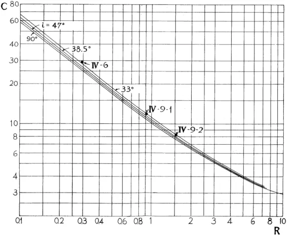
(11) The Drag of Lattice of Many Parallel Circular Cylinders at Low Reynolds Number ratios between drag coefficient of a cylinder set perpendicular and oblique are correctly expressed. In our specimens there are 5 singular points, i. e. 4 corners of the square and the lower center. To determine the C vs R curve of a cylinder set oblique, we must take into. consideration this singularity. But we could not use the method to determine this directly, since as yet it is unknown. Let us denote the ratios of drag coefficient of a cylinder for i =90° and 33° at the same. Reynolds number by Ao and A, where the former is the thoretical value by Tomotika et al. and the latter the experimental value. The mean value of A/Ao with regard to 3 experimental. data was 1.037, where the data of IV-6 was multiplied by 1/3 considering the weight of value. We may suppose that the value 0.037 originated from the above singularity, but the exact meaning of this number cannot be explained by these experiments only. Instead of the framework of the square, the author made a ciruclar one and attached. four legs symmetrically with the angle of incidence i =32°. Six specimens with different thickness were made and the drag coefficient of legs were measured by means of the same procedure. (The experiments were studied by H. Tsukui and M. Yamashita as a graduation. thesis.) The mean value of A/Ao in these specimens is 1.18 ±0.02 which is considerably larger than 1.037. The singularity of the circular framework is different from that of the square and therefore the end effects of the former may be less than the the latter. It is supposed. C 80 60 40 30. ^ ^ ^^ Sl" ^. 20. 10. =4!. 0. 18. ). ^. s ?^6\. M^ s K. (3 <. ^^. ^. I ^^^. ,-9-1. ^ e^ ^. >2. ^ ^.. Q1. 0,2 0.3 0,4 0,6 0.8 1. 2. 3 4. Fig. 10. Standard C vs R curves by the author of a circular cylinder set on several angles of incidence in a uniform flow.. — 19 -. 8 (0. R.
(12) Takashi Sawada. that because of the above reason the larger value of A/Ao was obtained in the circular framework. But the accuracy of this experiment is not so good, so we cannot deduce any decisive conclusion. In our case of a square framework, therefore, we may take 1.037 as. the suitable value of A/Ao. The process of drawing the C vs R standard curve for a circular cylinder oblique to a. main flow is as follows : At any Reynolds number the drag coefficient Ci is read from Wieselsberger's curve. At the same Reynolds number the drag coefficients Cio at ?'=90° and Cgo at z=33° are read from the theoretical curve by Tomotika, Aoi and Yosinobu. Ao=Cgo/. Cio is multiplied by the factors 1.037 and Ci. The result is Cy which is considered to be the most reliable value of the drag coefficient of the legs at ?'=33°. The value at i= 38.5° or 47° is calculated by assuming that the ratios of the drag coeffidents of the same Reynolds number at ?=33° and ?'==38.5° (or 47") are equal for both the theoretical and experimental curves. By this method we obtained the standard curves for calculation of drag of framework, supporting filaments and legs as shown in Fig. 10.. § 4. Relation between Drag Coefficient and Reynolds Number of Lattice The general method of experiment has already been mentioned. To vary the Reynolds number a small weight of lead was hung at the lower ends of legs by means of a thin nylon filament. The drag of the weight is very small in comparison with the other parts of specimen, so we can neglect it. The symbols necessary to show experimental data are. added as follows: n number of cylinders of lattice. suffix 3 supporting filaments 4 lattice 1. yi/d-=250 (/;-=5.0mm, n=ll) In this case the magnitudes of D^ D^ and Dy are of the same order as D^ so the errors by use of unsuitable standard curve may be quite large. But as shown in Fig. 11 we obtained quite satisfactory results. Some examples of experimental data are as follows:. 1) Specimen No. V-4 (Phot. 2) ^=5.31.10-3cm ,1=24.7 cm d, = 5.13 " 1, - 32.0 d, = 2.0 " ,3 - 6.2 d, = 2.00 " 1, - 67.9 v= 36.54cm.sec1 Do-= 3.548 dyn. R, - 1.270 C, - 8.58 D, - 0.890 R, - 1.227 C, - 9.61 D, - 0.670 R, - 0.478 C, - 17.35 D, -= 0.170 ^,-0.478 C,-16.9 D, -1.818. 2) Specimen No. III-10 d, = 6.74 • 10-3 cm 1, - 25.15 cm d, =5.2 " , 1,-= 24.4 d, - 2.35 " h - 6.2 20 -.
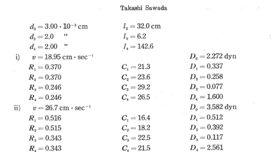
(13) The Drag of Lattice of Many Parallel Circular Cylinders at Low Reynolds Number d, = 1.99.10-3 cm. /, -= 68.6. 3) Specimen No. III-ll d, - 5.5 .10-3 cm. 1, = 25.14 cm. d, = 6,5 ". 1, = 29.08. d, == 2.0 ". ,3 = 12.5. d. -= 2.10 ". /, - 68.7. The angle of incidence of the legs of the specimen No. III-10 or 11 is larger than that of V-4, and the accuracy of measurement of the constant of the latter specimen is somewhat better than the former. But as shown in Fig. 11, the experimental data lie on one curve.. 30 r. c I SI^ I I h/d=250,n=11. ^. 20. oV-4,»ffl-10,effl-11 •^. h/d=l25.n=23 QV-5,-V-7. N^. N^. 10. 0.2 0,3 O.A- 0.5 0.6 OY 0.8 0.9 1.0. Fig. 11. Relation between C and R of the lattice of parallel. R. circular cylinders, in which hid is 250 and 125. 2. h/d=125 (/2-2.5mm, n-23) To obtain the specimen as light as possible, we used the cylinders of nearly 2.0/.< in diameter as framework and legs. By use of this, we obtained data at very low Reynolds number, but data beyond /?>0.4 were not accurate because of flexion of framework in falling. Some examples of experimental data are shown below.. 1) Specimen No. V-5 (Phot. 3) d, - 2.0 .10-3 cm. /i = 24.8 cm. d, = 2.1 ". 1, = 32.0. d, = 2,0 ". ,3-6.2. d, =2.00 ". 1, -142.6 D, = 2.274 dyn. v = 18.95 cm • see. 2). R, = 0.243. Ci - 29.6. D, = 0.308. R, == 0.255. C, = 31.8. D, = 0.241. R, = 0.243. C*3 -= 29.6. D3 = 0.077. R, = 0.243. C, = 27.6. D, -1.648. Specimen No. V-7 rf,-3.01.10 3 cm. /, -- 24.85 cm 21 -.
(14) Takashi Sawada 1, = 32.0 cm. d, = 3.00 .10-3 cm d, = 2.0 ". ,3 = 6.2. d,= 2.00 ". ./< = 142.6. A = 2.272 dyn. v == 18.95 cm- sec-1. R, = 0.370. D, = 0.337. C, --= 21.3. R, = 0.370. C, = 23.6. D, - 0.258. R, = 0.246. Cg - 29.2. D, = 0.077. ^=0.246. C, - 26.5. D, = 1.600. R, = 0.516. C, = 16.4. D, = 0.512. R, - 0.515. D, = 3.582 dyn. v == 26.7cm • sec-l. C, -18.2. D, = 0.392. 7?3 -= 0.343. C, = 22.5. £>3 = 0.117. R, = 0.343. C, = 21.5. D, = 2.561. The C vs R relation is shown in Fig. 11, which on the whole is the same as in hjd==. 250. Thus we can see that the C vs R curve of the lattice is a little below the standard curve at lower Reynolds number, but approaches to it at the higher R number. Considering the degree of the accuracy of our experiments we may say that the above two curves coincide with each other and there exist no remarkable interferences in the interior of the lattice. Furthermore we can say that the standard curve expresses the C vs R relationship of an isolated circular cylinder. 3. h/d==100 (/z=2.0mm,, w=29) In this and the next cases we could not perceive any distinct effects of interference of cylinders of lattice. The C vs R curves are nearly the same as in the previous cases. See Fig. 12. Some examples of experimental data are shown below.. c. 30. 20. 10. 0.2. -^. ^. TI. T. h/d=100.n=29 oV-l.»m-6. ^h/d=7'5.n=39 °V-6,-ffl-3. NM 03 0.4 0.5 0.6 0.7 0.8 0.9 1.0. R. Fig. 12. Relation between C and R of the lattice of parallel circular cylinders, in which hid is 100 and 75.. 1) Specimen No. V-l (Phot. 4) d, - 3.78 • 10-3 cm /, -- 24.5 cm 22 -.
(15) The Drag of Lattice of Many Parallel Circular Cylinders at Low Reynolds Number ^=5.60.10-3cm. 1, = 32.0 cm. d, - 2.0 ". ,3=6.2. ^=1.99 ". ,4 = 177.5. A = 4.184 dyn. i) y= 26.17cm • sec-l. R, = 0.650. C, = 13.8. D, - 0.519. R, = 0.963. C, = 11.4. D, = 0.446. R, = 0.344. C, = 22.4. D, = 0.113. 2?4 = 0.342. C, = 21.68. D, = 3.106 Do -14.02 dyn. ii) v == 65.3cm • sec-l. R, = 1.630. C, = 7.32. D, = 1.73. R, - 2.416. C, - 6.15. D, = 1.51. 7?3 = 0.863. C, = 11.13. D, = 0.35. /?4 = 0.858. C, = 11.68. D, = 10.43. 2) Specimen No. III-6 ^-6.75.10-3cm. /i = 25.2 cm. d, = 4.77 ". /, = 28.7. d, =- 2.05 ". ,3-=6,2. ^-1.99 ". /, -184 Do - 5.607 dyn. v ^31.92 cm • sec-1. R, = 1.552. C, -- 7.52. D, - 0.771. R, -= 1.103. a -- 9.98. D, - 0.528. R, - 0.471. C, -= 17.6. D, -- 0.140. R, •-= 0.457. C< -17.75. D, - 4.168. 4. /t/d-75 (/?=1.5mm, n-39) Some examples are shown below.. 1) Specimen No. V~6 (Phot. 5) ^-=3.96.10 3 cm. /, -= 24.83 cm. ^-3.57 ". /, = 32.0. d, --= 2.0 ". ,3-6.2. ^-2.00 ". /, = 242. i) y = 23.15 cm- sec-1. D, = 4.455 dyn. R, = 0.588. C, -14.8. R, = 0.530. C, = 17.8. D^ = 0.343. R, == 0.297. C, = 25.1. D, - 0.098. R, - 0.297. C^ - 23.5. D, -= 3.558. R, = 1.298. C, = 8.48. A -= 1.29. R, = 1.171. C, == 9.92. D, == 0.94. R, = 0.656. C, = 13.65. D, = 0.26. R^ = 0.656. C, -13.61. D, = 10.18. ii) v--= 51.65 cm • sec '. D, - 0.456. D, •-= 12.67 dyn. 2) Specimen No. III-3 d, - 7.68 .10-3 cm. /i - 24.95 cm. ^-5.04 ". 1, ---- 30.5. d., -= 2.0 ". /,-6.2 - 23.
(16) Takashi Sawada /, = 246 cm. d, = 1.89 .10-3 cm. 5. A/d=50 {h =1.0 mm, n -59) Some examples of experimental data are as follows:. 1) Specimen No. V-3 (Phot. 6) ^ = 4.02 • 10-3 cm d, -5.23 " d, - 2.0 ". 24.8 cm. 1.. h h. -32.0. 6.2. 1.. -368. R, - 0.546. c,. -15.7. D, = 0.40. R, = 0.711. ^=2.00 ". Do - 5.49 dyn. i) v = 20.66 cm •sec-l. c,. -14.2. D^ = 0.32. R, - 0.272. c,. 27.0. D, --= 0.09. R, = 0.272. c,. 25.0. D, = 4.68. A = 19.80 dyn. ii) v = 55.2 cm •see"1. 7.7. c,. 7A. A -1.30. c,. 13.1. D, = 0.28. c,. 13.2. D, --17.09. R, = 1.403. c,. R, -1,827 R, = 0.699 R, - 0.699. D, = 1.13. 2) Specimen No. III-2 d, - 6.15 .10-3 cm. h-. 10.1 ". ^-4.12 " d, = 2.0 " d, =1.90 ". oV-3,®ffl-2,©ffl-12. h/d=25.n=119. h/d=125.n=239 AV-8 Q5 0.6 0.7 08.0.9 1.0 Fig. 13.. Relation between C and R of the lattice of parallel circular cylinders, in which h/d is 50, 25 and 12.5.. — 24 —. R.
(17) The Drag of Lattice of Many Parallel Circular Cylinders at Low Reynolds Number In preparing the specimen, the glass filament of one side of the framework was broken,. so this side was repaired by additional filament. The second line of d^ is the projected width of this side. In spite of these unpardonable circumstances, the C vs R relation was the same as the other normal specimens.. 3) Specimen No. III-12 d, == 4.94 .10-3 cm /, - 25.35 cm d^ == 3.8 " ,2 === 25.3. ^=2.5 " /a = 6.25 d, ==2.06 " ,,=372. The C vs R relation is shown in Fig. 13. We can perceive a slightly larger effect of interference between cylinders compared with the former cases. 6. h/d=25 (/z=0.5mm, %=119) In this case the effects of interference of cylinders are remarkable. Some examples of experimental data are as follows : Specimen No. V-2 (Phot. 7) d, = 6.0 .10-3 cm - I, == 24,7 cm d, -- 6.8 " /, - 32.0 a'3-2.0 " . ,3.== 12.4. ^-1.98 " ,,-=739 i) v = 22.42 cm . see-1 D, = 10.42 dyn R, = 0.887 C, -= 10.9 D, --= 0.48. ^=1.005 C,= 11.15 D, -0.39 R, = 0.296 C, = 25.3 D, = 0.19 R, - 0.293 C^ = 21.4 D^ - 9.36 ii) v - 71.6 cm . see-1 Do - 52.92 dyn R, = 2.86 C, == 5.24 D, = 2.38. R, = 3.24 C, = 5.15 D, = 1.85 R, == 0.953 C, = 10.4 D, = 0.79. R, = 0.943 C, = 10.68 D, = 47.90 On account of interference of cylinders, strictly spe aking we ought not to use the standard curve of isolated cylinder to calculate the drag of framework and supporting filaments. But as seen above, Z)p D^ and Dy are small compared with D^, so their errors may be neglected.. The C vs R relation is shown in Fig. 13, in which the curve tends asymtotically to coincide with the standard curve of isolated cylinder at higher Reynolds number. 7. 7i/d=12.5 (/z-0.25mm, %-239). To prepare this specimen with handwork is very difficult, because the adjacent filaments are brought close together by a slight irregularity. To keep exactly the normal position of filaments, six aupporting filaments were used, of which two filaments stood as a pair, with the lattice inserted, respectively, and were pasted together. In reality the thickness of supporting filaments is, therefore, larger than 20 p.. Because the drag of the supporting filaments is very small compared with other parts of drag of the specimen, the author did not correct the thickness of the supporting filaments. As seen in Phot. 8, the author was unable to keep the filaments of lattice perfectly in normal position. — 25 —.
(18) Takashi Sawada Some examples of experimental data are as follows: Specimen No. V-8 (Phot.. 8). d, = 6.9 • 10-3 cm. /i = 24.7 cm. d, = 7.6 ". 1, = 32.0. d, = 2.0 ". 1, == 18.4. ^=2.00 ". 1, = 1480 Do = 17.89 dyn. i) v = 27.1 cm •see"1. R, = 1.197. C, = 8.9. D, = 0.65. R, -1.318. C, = 9.3. D, = 0.52. R, - 0.347. C.3 = 22.3. D, - 0.35. R, = 0.347. C, = 12.9. D, -16.37. ii) v^ 51.53 cm- see"1. Do = 53.90 dyn. R, = 2.304. C, - 5.94. D, = 1.57. R, = 2.540. C, = 5.97. D, = 1.21. R, = 0.668. C*3 -13.5. D, - 0.77. R, = 0.668. C, -10.96. D, - 50.35. iii) v -=66.3 cm • sec l. £>„ - 78.15 dyn. R, = 2.95. C, = 5.15. R, -= 3.25. C, -= 5.15. R, -- 0.856. C, -- 11.15. D, --1.06. R, --- 0.856. C, - 9.54. D, -- 73.08. D, = 2.27 1.74. The C vs R relation is shown in Fig 13. The effects of interference of cylinders are very remarkable, but at the higher Reynolds number the curve seems to approach to the standard curve of an isolated cylinder as in previous cases. The apparent drag coefficient of lattice Cap=Cd/h cannot, as discussed later, exceed the value of the drag coeflficient of. C30[;. 20. Pig. 14. Summarization of C vs R curves of the lattice of parallel circular cylinders with several values of h/d. — 26 -.
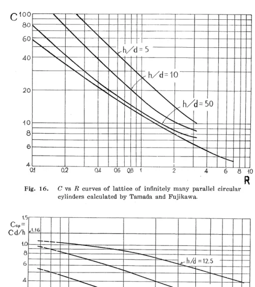
(19) The Drag of Lafctice of Many Parallel Circular Cylinders at Lo\v Reynolds Number square plate, which is 1.12~1 16, provided the Reynolds numbers were greater than 100016)'17). Summerizing the above results, we obtain Fig. 14.. § 5. Discussion of the Results According to Fujikawa's calculation the C vs R curves of two parallel cylinders are as Fig. 15. The features of these are very similar to our results. In general the smaller the value of hid, the more deviates the C vs R curve from that of the isolated cylinder, but the former approaches asymtotically to the latter at higher Reynolds number.. The C vs R curves of lattice of infinitely many parallel circular cylinders in two dimensions calculated by Tamada and Fujikawa are shown in Fig. 16. The relations between these curves and that for an isolated cylinder are in the opposite trend to our results. If, however, we use not the falling velocity of specimen but the actual velocity of flow through the lattice to calculate the drag coefficient, we would obtain the curves similar to Fig. 16. The apparent drag coefficient of the specimen is calculated by Cap==Cd/h, and the apparent Reynolds number is Rap==lvlv, where / ==6.0 cm is the length of one side of square specimen. The Cap vs Rap relations are shown in Fig. 17, which seem not to be able to exceed the value of a square plate near Ra^==1000 no matter how small the value of hid is. The value of the drag coefficient of isolated cylinder at R ==0.3, Co, is 25.0. Let us represent as C the experimental value of drag coefficient of lattice at the same Reynolds number. In Fig. 18 are shown the (I—C/C^-IOO vs h/d relations, where the curve by calculation is as follows : We assume that the apparent drag coefficient of lattice cannot exceed 1.16, i. e. the value of the drag coefficient of square plate no matter how small the value of h/d is. The drag coefficient of lattice which gives Cap^l.16, i. e. C'==l. 16 hid will become .4001. 100. 100. ^ ^$ ^. .h/ l=c 0. >k,. 80. -K. )0. s^. •^. s:. 5( I ^. "^. s^.. ^ ^-. s,. 60 40. <. "^. ^. 20. 101. 0.01. 0.02 Fig. 15.. 0.04, 0.06 0.06 0.1. ^^ ^. Q2. 0.4. C vs R curves of two parallel circular. cylinders calculated by Fujikawa. - 27 —. ^ 0.6. 0.8 1. R.
(20) Takashi Sawada. c100. 80 ^. 60. :s:. s:. ^s. "Y. sTY. 40. x^ ^\. s,. ass. 20. s:^. s. \. \ "s. \ .h/d: N1. s,. \. ^. \. s,. s. \[s / / s. s. 5. ^cr. s. ^0. )". <. ^^ s:. s. 0.1. 03.. J=-. 0. !'k.. w. OA 0.6 Q.8 \. Fig. 16. C vs I? curves of lattice of infinitely many parallel circular cylinders calculated by Tamada and Fujikawa.. R. 1.5 'ap. Cd/h. ^1,16. 1.01 .^h/d=12.5 ••«.. Jt. ^.. 0.1. 103. 25. .50. 6 8 10+ Rap=3-103R. Fig. 17. Cap VS -Rn/; curves of the lattice of many. parallel circular cylinders.. - 28 -.
(21) The Drag of Lattice of Many Parallel Circular Cylinders at Low Reynolds Numbers. (\-^)-w /100f. 801 60. ^. 401 20. ^. c •^r. Ca. 'CL. ^. s.. 'e.. /c tion. Curve by Ex. Fig. 18.. iment ent. 0. x "^. ^. ^0. 4. 3&. ^ ^A_ ^. M. 2 A- 6 810 20 40 6080100 200 Relation between (l—CVCy'100 and h/d, where C and Co represent respectively drag coeflBcient of lattice and an isolated circular cylinder at ^=0.3.. larger with increasing h/d, but cannot exceed 25.0, that is, the value of the drag coefficient of an isolated cylinder. If h/d= 21,55, then C'= 25.0. By means of the above formula we calculate C' for h/d<21.55, and plot (l-C-'/C)-100 against hid. Thus we obtain the curve by calculation. It may be supposed that the curve by experiment will approach asymtotically. to it at smaller value of hid. § 6. Acknowledgement The author wishes to express his sincere thanks to Prof. U. Nakaya for his continued encouragement throughout this work, and to Profs. I. Imai, K. Tamada, Y. Takaisi and H.. Fujikawa for their kind interest and discussions. References. 1) T. Sawada: J. Hokkaido Gakugei Univ. 7 (1956) 63 (in Japanese). 2) H. Fujikawa: J. Phys. Soc. Japan 11 (1956) 558. 3) T. Tamada and H. Fujikawa : Quart. J. Mech. Appl. Math. 10 (1957) 423. 4) T. Miyagi: J. Phys. Soc. Japan 13 (1958) 493. 5) S. Tomotika and T. Aoi : Mem. Coll. Sci. Univ. Kyoto A 26 (1950) 183. 6) I. Imai: Univ. Maryland, Inst. Fluid Dyn. & Appl. Math., Tech. Note BN-104 (1957). 7) H. Lamb: Hydrodynamics, 6 th ed. (Cambridge, 1932) 615. 8) M. Kawaguti: J. Phys. Soc. Japan 8 (1953) 747. 9) S. Brodetsky: Proc. Roy. Soc. London A 102 (1923) 542. 10) A. Thorn: Proc. Roy. Soc. London A 141 (1933) 653. 11) W. Muller: Einfuhrung in die Theorie der zahen Fliissigkeiten (Leibzig, 1932). 12) C. Wieselsberger: Phys. Z. 22 (1921) 321. 13) H. Schlichting: Grenzschicht-Theorie (Karlsruhe, 1951) 15. 14) R. Finn; J. Appl. Phys. 24 fl953) 771. 15) S. Tomotika, T. Aoi and H. Yosinobu: Proc. Roy. Soc. London A 219 (1953) 233. 16) H. Dryden et al: Hydrodynamics (Dover, 1956) 14. 17) B. Fujimoto: Applied Hydrodynamics (Maruzen, 1941) 484 (in Japanese).. — 29 —.
(22) T. SAW ADA : Specimens of Framework and Lattice.. Blan.vie.w .(Neg. -No. 6-76)' Side .view (Negi No>. 6-7-7) i Phot.:;!. , Specfmen-No." IiV-t-9^. framework and legs.. Plan view (Neg. No. 7-40) Side view (Neg. No. 7Phot. 2. Specimen No. V-4, /i/d=250, '?=11.. SAWADA Photo. 31. Plate 1.
(23) Plate 2. T. SAWADA : Specimens of Lattice.. Plan view (Neg. No. 7-74) Side view (Neg. No. 7-75) Phot. 3. Specimen No. V-5, h/d=125, w=23.. Plan view (Neg. No. 7-37) Side view (Neg. No. 7-65) Phot. 4. Specimen No. V-l, h/ 'd =100, w=29.. SAWADA' Photo. — 32 —.
(24) T. SAWADA : Specimens of Lattice.. Plate 3. Plan view (Neg. No. 7-79) Side view (Neg. No. 7-81) Phot. 5. Specimen No. V-6, h/d=75, w=39.. Plan view (Neg. No. 7-39) Side view (Neg. No. 7-67) Phot. 6. Specimen No. V-3, h/d=50, TO =59.. SAWADA Photo. — 33.
(25) Plate 4. T. SAWADA : Specimens of Lattice.. Plan view (Neg. No. 7-38) Side vie'w!(Neg. No. 7-86) Phot. 7. Specimen No. V-2, h/d^25, n= 119.. Plan view (Neg. No. 7-105) Side view (Neg. No. 7-107) Phot. 8. Specimen No. V-8, /i/d=12.5, n=- 239.. SAWADA Photo. — 34.
(26)
図


+3
関連したドキュメント
Keywords: continuous time random walk, Brownian motion, collision time, skew Young tableaux, tandem queue.. AMS 2000 Subject Classification: Primary:
This paper is devoted to the investigation of the global asymptotic stability properties of switched systems subject to internal constant point delays, while the matrices defining
In this paper, we focus on the existence and some properties of disease-free and endemic equilibrium points of a SVEIRS model subject to an eventual constant regular vaccination
Classical definitions of locally complete intersection (l.c.i.) homomor- phisms of commutative rings are limited to maps that are essentially of finite type, or flat.. The
This paper gives a decomposition of the characteristic polynomial of the adjacency matrix of the tree T (d, k, r) , obtained by attaching copies of B(d, k) to the vertices of
Yin, “Global existence and blow-up phenomena for an integrable two-component Camassa-Holm shallow water system,” Journal of Differential Equations, vol.. Yin, “Global weak
This paper presents an investigation into the mechanics of this specific problem and develops an analytical approach that accounts for the effects of geometrical and material data on
We study the classical invariant theory of the B´ ezoutiant R(A, B) of a pair of binary forms A, B.. We also describe a ‘generic reduc- tion formula’ which recovers B from R(A, B)
