B7FY-A007-01
ファイバチャネルカード
ファイバチャネルカード
ファイバチャネルカード
ファイバチャネルカード PG-FC102/103 ご使用前に
ご使用前に
ご使用前に
ご使用前に
この度は、弊社のファイバチャネルカードPG-FC102/PG-FC103(以後、本製品と呼びます)をお買い 求めいただきまして、まことにありがとうございます。本書は、本製品に添付されている取扱説明書の記 述を補足しております。本製品をご利用になる前に必ずお読みください。 2002 年 6 月 富士通株式会社1 概要
概要
概要
概要
本書は、ファイバチャネルカードの BIOS の設定、および、デバイスドライバのアップデート作業に ついて取扱説明書を補足しています。2 フロッピィ
フロッピィ
フロッピィ
フロッピィ
ドライバのインストールには以下のフロッピィディスクを使用します。 ! 「PG-FC102/103 Windows NT 4.0 Drivers Disk」 × 1 ! 「PG-FC102/103 Windows 2000 Drivers Disk」 × 13 Fast!UTIL について
について
について
について
本製品の BIOS 版数が 1.77 以降の場合、Fast!UTIL を起動する為のキーが[Ctrl]+[Q][Ctrl]+[Q][Ctrl]+[Q][Ctrl]+[Q]になり ます。 Fast!UTIL を使用する際は、サーバ本体起動時に以下のメッセージが表示されたら、[Ct[Ct[Ct[Ctrl]rl]rl]キーrl] と[Q][Q][Q]キーを同時に押して、起動してください。 [Q] QLogic Corporation QLogic Corporation QLogic Corporation QLogic CorporationQLA2200 PCI Fibre Channel ROM BIOS Version x.xx QLA2200 PCI Fibre Channel ROM BIOS Version x.xx QLA2200 PCI Fibre Channel ROM BIOS Version x.xx QLA2200 PCI Fibre Channel ROM BIOS Version x.xx Copyright (C) QLogic Corporation 1993
Copyright (C) QLogic Corporation 1993 Copyright (C) QLogic Corporation 1993
Copyright (C) QLogic Corporation 1993---2002. All right reserved.-2002. All right reserved.2002. All right reserved.2002. All right reserved. www.qlogic.com
www.qlogic.com www.qlogic.com www.qlogic.com
Press <CTRL+Q> for Fast!UTIL Press <CTRL+Q> for Fast!UTIL Press <CTRL+Q> for Fast!UTIL Press <CTRL+Q> for Fast!UTIL
4 BIOS の設定について
の設定について
の設定について
の設定について
サーバ本体起動時(OS 起動時の POST 時)に以下のメッセージが出力されたら、[Ctrl][Ctrl][Ctrl][Ctrl]キーと [Q [Q [Q [Q]]]キーを同時に押し、Fast!UTIL を起動してください。 ] QLogic Corporation QLogic Corporation QLogic Corporation QLogic CorporationQLA2200 PCI Fibre Channel ROM BIOS Version 1.77 QLA2200 PCI Fibre Channel ROM BIOS Version 1.77 QLA2200 PCI Fibre Channel ROM BIOS Version 1.77 QLA2200 PCI Fibre Channel ROM BIOS Version 1.77 Copyright (C) QLogic Corporation 1993
Copyright (C) QLogic Corporation 1993 Copyright (C) QLogic Corporation 1993
Copyright (C) QLogic Corporation 1993---2002. All right reserved.-2002. All right reserved.2002. All right reserved.2002. All right reserved. www.qlogic.com
www.qlogic.com www.qlogic.com www.qlogic.com
Press <CTRL+Q> for Fast!UTIL Press <CTRL+Q> for Fast!UTIL Press <CTRL+Q> for Fast!UTIL Press <CTRL+Q> for Fast!UTIL
本製品が 2 枚以上搭載されている場合は、カードを選択する為の画面が表示されます。Fast!UTIL で使用するカードを選択し、[ENTER]キーを押してください。
Fast!UTIL が起動すると、以下のメニューが表示されます。
Configuration Settings Configuration Settings Configuration Settings Configuration Settings Scan Fibre Devices Scan Fibre Devices Scan Fibre Devices Scan Fibre Devices Fibre Disk Utility Fibre Disk Utility Fibre Disk Utility Fibre Disk Utility Loopback Data Test Loopback Data Test Loopback Data Test Loopback Data Test Select Host Adapter Select Host Adapter Select Host Adapter Select Host Adapter Exit Fast!UTIL Exit Fast!UTIL Exit Fast!UTIL Exit Fast!UTIL
「Configuration SettingsConfiguration SettingsConfiguration SettingsConfiguration Settings」を選択してください。更にサブメニューが表示されますので、 「Host Host Host Adapter SettingsHost Adapter SettingsAdapter Settings」、「Selectable Boot SettingsAdapter Settings Selectable Boot SettingsSelectable Boot SettingsSelectable Boot Settings」、「Advanced Adapter Advanced Adapter Advanced Adapter Advanced Adapter Settings
Settings Settings
Settings」、「Extended Firmware SettingsExtended Firmware SettingsExtended Firmware SettingsExtended Firmware Settings」のそれぞれの設定値が、以下の表と同じで あることを確認してください。また、設定値が表と異なる場合は、下記の表に従って設定を行ってく ださい。
☛
接続する装置により設定値が異なる場合があります。接続する装置により設定値が異なる場合があります。接続する装置により設定値が異なる場合があります。接続する装置により設定値が異なる場合があります。☛
GR シリーズは下記の機種を示します。シリーズは下記の機種を示します。シリーズは下記の機種を示します。 シリーズは下記の機種を示します。GR710 / GR720 / GR730 / GR740 / GR820 / GR840
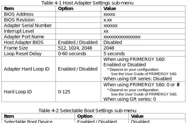
表 4-1 Host Adapter Settings サブメニュー
項目 項目 項目 項目 オプションオプションオプションオプション 設定値設定値設定値設定値 BIOS Address xxxxx BIOS Revision x.xx
Adapter Serial Number xxxxxx
Interrupt Level xx
Adapter Port Name xxxxxxxxxxxxxxxx Host Adapter BIOS Enabled / Disabled Disabled Frame Size 512, 1024, 2048 2048 Loop Reset Delay 0-60 seconds 5 seconds
Adapter Hard Loop ID Enabled / Disabled
PRIMERGY S60 接続時: Enabled 又は Disabled ※ご使用の構成により異なります。詳しくは PRIMERGY S60 取扱説明書を参照して ください。 GR シリーズ接続時: Disabled Hard Loop ID 0-125 PRIMERGY S60 接続時: 0 又は1 ※ご使用の構成により異なります。詳しくは PRIMERGY S60 取扱説明書を参照して ください。 GR シリーズ接続時: 0
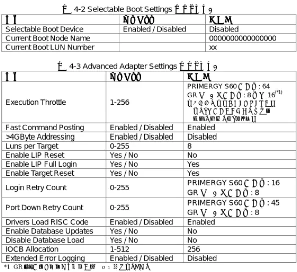
表 4-2 Selectable Boot Settings サブメニュー
項目 項目 項目
項目 オプションオプション オプションオプション 設定値設定値 設定値設定値 Selectable Boot Device Enabled / Disabled Disabled
Current Boot Node Name 0000000000000000
Current Boot LUN Number xx
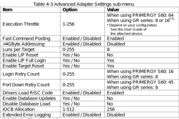
表 4-3 Advanced Adapter Settings サブメニュー
項目 項目 項目 項目 オプションオプションオプションオプション 設定値設定値 設定値設定値 Execution Throttle 1-256 PRIMERGY S60 接続時: 64 GR シリーズ接続時: 8 又は 16(*1) ※ご使用の構成により異なります。 詳しくは接続する装置の取扱説 明書を参照してください。
Fast Command Posting Enabled / Disabled Enabled >4GByte Addressing Enabled / Disabled Disabled
Luns per Target 0-255 8
Enable LIP Reset Yes / No No Enable LIP Full Login Yes / No Yes Enable Target Reset Yes / No Yes
Login Retry Count 0-255 PRIMERGY S60 接続時: 16 GR シリーズ接続時: 8 Port Down Retry Count 0-255 PRIMERGY S60 接続時: 45
GR シリーズ接続時: 8 Drivers Load RISC Code Enabled / Disabled Enabled
Enable Database Updates Yes / No No Disable Database Load Yes / No No
IOCB Allocation 1-512 256
Extended Error Logging Enabled / Disabled Disabled
*1 GR シリーズを接続する場合以下の設定値になります。 MSCS または SafeCLUSTER 構成の場合 : 8888
1 つの FC-CA(FC ポート)当たりに接続されるファイバチャネルカード数が 1 の場合 : 16161616 1 つの FC-CA(FC ポート)当たりに接続されるファイバチャネルカード数が 2 以上の場合 : 8888
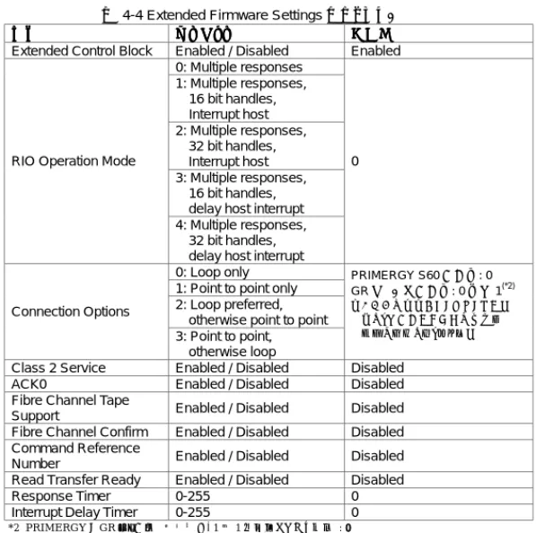
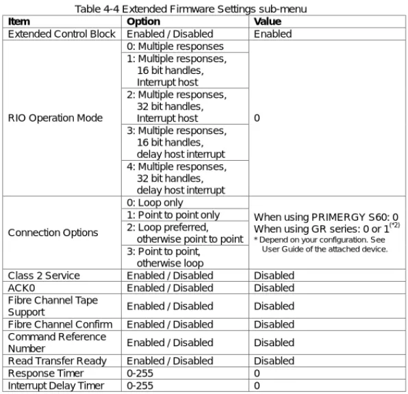
表 4-4 Extended Firmware Settings サブメニュー
項目 項目 項目
項目 オプションオプション オプションオプション 設定値設定値設定値設定値 Extended Control Block Enabled / Disabled Enabled
0: Multiple responses 1: Multiple responses, 16 bit handles, Interrupt host 2: Multiple responses, 32 bit handles, Interrupt host 3: Multiple responses, 16 bit handles, delay host interrupt RIO Operation Mode
4: Multiple responses, 32 bit handles, delay host interrupt
0
0: Loop only 1: Point to point only 2: Loop preferred, otherwise point to point Connection Options 3: Point to point, otherwise loop PRIMERGY S60 接続時: 0 GR シリーズ接続時: 0 又は 1(*2) ※ご使用の構成により異なります。 詳しくは接続する装置の取扱説 明書を参照してください。
Class 2 Service Enabled / Disabled Disabled ACK0 Enabled / Disabled Disabled Fibre Channel Tape
Support Enabled / Disabled Disabled Fibre Channel Confirm Enabled / Disabled Disabled Command Reference
Number Enabled / Disabled Disabled Read Transfer Ready Enabled / Disabled Disabled
Response Timer 0-255 0
Interrupt Delay Timer 0-255 0
*2 PRIMERGY と GR シリーズの装置間を、1 対 1 で接続している場合 : 0000
PRIMERGY と GR シリーズの装置間に SN200 等のファイバチャネルスイッチが接続されている場合 : 1111 詳しくは接続する装置の取扱説明書を参照してください。
5 デバイスドライバのインストール
デバイスドライバのインストール
デバイスドライバのインストール
デバイスドライバのインストール
本製品をサーバ本体にはじめて搭載した場合は、本製品の取扱説明書の「4 ドライバのインストー ル」を参照し、デバイスドライバのインストールを行なってください。6 デバイスドライバのアップデート
デバイスドライバのアップデート
デバイスドライバのアップデート
デバイスドライバのアップデート
サーバ本体に既に本製品が搭載されており、さらに本製品を追加搭載する場合は、以下の手順に 従ってデバイスドライバをアップデートしてください。6.1 Windows NT 4.0 の場合
の場合
の場合
の場合
Windows NT 4.0 をご使用の場合、以下の手順に従ってデバイスドライバのアップデートを行ってく ださい。 1. Administrator でログインしてください。 2. 「スタート」ボタンをクリックし、「設定」→「コントロールパネル」を選択してください。 3. 「コントロールパネル」ウィンドウの SCSI アダプタアイコンをダブルクリックしてください。 4. 「SCSI アダプタ」ウィンドウの「ドライバ」タブをクリックし、「ドライバ」タブを前面に表示させてく ださい。 5. 「追加」をクリックしてください。「ドライバのインストール」ウィンドウが表示されます。 6. 「ディスク使用」ボタンをクリックしてください。7. 「PG-FC102/103 Windows NT 4.0 Drivers Disk」と書いてあるフロッピィディスクをフロッピ ィディスクドライブに挿入してください。
8. 「フロッピィディスクからインストール」ウィンドウで「配布ファイルのコピー元:」を「A:¥nt」に変 更し、「OK」をクリックしてください。
9. 「ドライバのインストール」ウィンドウで、「QLogic QLA2200 PCI Fibre Channel Adapter」を 選択し、「OK」をクリックしてください。 10. 「システム設定の変更」ウィンドウが表示されたら、フロッピィディスクをフロッピィディスクドライ ブから取り出し、「はい」をクリックしてシステムを再起動させてください。
6.2 Windows
2000 の場合
の場合
の場合
の場合
Windows 2000 をご使用の場合、以下の手順に従ってデバイスドライバのアップデートを行ってくだ さい。 1. Administrator でログインしてください。 2. インストールを実行する前に、すべてのプログラムを終了してください。 3. 「コントロールパネル」から「システム」を実行してください。 4. 「ハードウェア」タブを選択し、「デバイスマネージャ」をクリックしてください。5. 「SCSI と RAID コントローラ」をダブルクリックしてください。SCSI アダプタの一覧が表示され ます。「QLogic QLA2200 PCI Fibre Channel Adapter」をダブルクリックしてください。 6. プロパティウィンドウが表示されたら、「ドライバ」タブを選択し、「ドライバの更新」をクリックして
ください。「デバイスドライバのアップグレードウィザード」ウィンドウが表示されますので、「次 へ」をクリックしてください。
7. 「このデバイスの既知のドライバを表示して、その一覧から選択する」を選択し、「次へ」をクリッ クしてください。
8. 「ディスク使用」をクリックし、フロッピィディスクドライブに「PG-FC102/103 Windows 2000 Drivers Disk」を挿入してください。
9. 「製造元のファイルのコピー元」に”A:¥w2k”と入力して、「OK」をクリックしてください。 10. モデル欄からデバイスドライバを選択します。「QLogic QLA2200 PCI Fibre Channel
Adapter」を選択し、「次へ」をクリックしてください。 11. もう一度「次へ」をクリックすると、デバイスドライバのインストールが開始されます。 12. デバイスドライバのコピーが完了したら、「完了」をクリックし、「デバイスドライバのアップグレー ドウィザード」ウィンドウを閉じてください。 13. プロパティウィンドウの「閉じる」をクリックしてウィンドウを閉じてください。
☛
「システム設定の変更」ウィンドウが表示された場「システム設定の変更」ウィンドウが表示された場「システム設定の変更」ウィンドウが表示された場「システム設定の変更」ウィンドウが表示された場合は、「いいえ」をクリックしてくださ合は、「いいえ」をクリックしてくださ合は、「いいえ」をクリックしてくださ合は、「いいえ」をクリックしてくださ い。 い。 い。 い。 14. サーバ本体に搭載されているすべてのファイバチャネルカード(PG-FC102/103)について、 手順5~13 を繰り返してください。 15. すべてのファイバチャネルカードについてデバイスドライバのアップデートが完了したら、シス テムの再起動してください。Microsoft 、 Windows お よ び Windows NT は 、 米 国 Microsoft Corporation の米国およびその他の国における登録商標です。 QLogic は QLogic 社の登録商標です。
Fibre Channel Card PG-FC102/103 Supplement
Thank you for your purchase of the Fujitsu Fibre Channel Card PG-FC102/PG-FC103 (hereinafter simply called this product). This document provides additional explanations for the User Guide that is supplied with this product. Read this document before you start using this product.June 2002, Fujitsu Limited
1 Summary
This document shows BIOS settings and device driver update procedure for Fibre Channel Card.
2 Floppy
Disks
The following floppy disks required for the device driver installation. ! PG-FC102/103 Windows NT 4.0 Drivers Disk ! PG-FC102/103 Windows 2000 Drivers Disk
3 About
Fast!UTIL
To start Fast!UTIL, press the [Ctrl][Ctrl][Ctrl][Ctrl] and [Q][Q][Q][Q] keys at the same time while the following message is displayed on screen at the boot-up of the server.
QLogic Corporation QLogic Corporation QLogic Corporation QLogic Corporation
QLA2200 PCI Fibre Channel ROM BIOS Version x.xx QLA2200 PCI Fibre Channel ROM BIOS Version x.xx QLA2200 PCI Fibre Channel ROM BIOS Version x.xx QLA2200 PCI Fibre Channel ROM BIOS Version x.xx Copyright (C) QLogi
Copyright (C) QLogi Copyright (C) QLogi
Copyright (C) QLogic Corporation 1993c Corporation 1993c Corporation 1993c Corporation 1993---2002. All right reserved.-2002. All right reserved.2002. All right reserved.2002. All right reserved. www.qlogic.com
www.qlogic.com www.qlogic.com www.qlogic.com
Press <CTRL+Q> for Fast!UTIL Press <CTRL+Q> for Fast!UTIL Press <CTRL+Q> for Fast!UTIL Press <CTRL+Q> for Fast!UTIL
4 BIOS
Settings
To start Fast!UTIL at the boot-up of the server. When two or more cards are mounted in the server, the window to select card appears first. Using arrow keys, select the card for which you want to use
Fast!UTIL, then press the [Enter][Enter][Enter][Enter] key.
After Fast!UTIL has started up, the following menu appears on screen.
Configuration Settings Configuration Settings Configuration Settings Configuration Settings Scan Fibre Devices Scan Fibre Devices Scan Fibre Devices Scan Fibre Devices Fibre Disk Utility Fibre Disk Utility Fibre Disk Utility Fibre Disk Utility Loopback Data Test Loopback Data Test Loopback Data Test Loopback Data Test Select Host Ada Select Host Ada Select Host Ada Select Host Adapterpterpterpter Exit Fast!UTIL Exit Fast!UTIL Exit Fast!UTIL Exit Fast!UTIL
Select “Configuration SettingsConfiguration SettingsConfiguration SettingsConfiguration Settings” to open sub-menu. Confirm that the parameters of “Host Host Host Host Adapter Settings
Adapter Settings Adapter Settings
Adapter Settings”, “Selectable Boot SettingsSelectable Boot SettingsSelectable Boot SettingsSelectable Boot Settings”, “Advanced Adapter Advanced Adapter Advanced Adapter Advanced Adapter Settings
Settings Settings
Settings” and “Extended Firmware SettingsExtended Firmware SettingsExtended Firmware SettingsExtended Firmware Settings” are same as tables below. If the parameters differ from the value of tables, change that parameter to same value.
☛
Some parameters may differ from tables below according to attached devices. See the manual of attached device for details.☛
GR series indicate following device.GR710 / GR720 / GR730 / GR740 / GR820 / GR840
Table 4-1 Host Adapter Settings sub-menu
Item Option Value
BIOS Address xxxxx
BIOS Revision x.xx
Adapter Serial Number xxxxxx
Interrupt Level xx
Adapter Port Name xxxxxxxxxxxxxxxx Host Adapter BIOS Enabled / Disabled Disabled Frame Size 512, 1024, 2048 2048 Loop Reset Delay 0-60 seconds 5 seconds
Adapter Hard Loop ID Enabled / Disabled
When using PRIMERGY S60: Enabled or Disabled
* Depend on your configuration. See the User Guide of PRIMERGY S60.
When using GR series: Disabled
Hard Loop ID 0-125
When using PRIMERGY S60: 0 or 1
* Depend on your configuration. See the User Guide of PRIMERGY S60.
When using GR series: 0
Table 4-2 Selectable Boot Settings sub-menu
Item Option Value
Selectable Boot Device Enabled / Disabled Disabled
Current Boot Node Name 0000000000000000
Table 4-3 Advanced Adapter Settings sub-menu
Item Option Value
Execution Throttle 1-256
When using PRIMERGY S60: 64 When using GR series: 8 or 16(*1)
* Depend on your configuration. See the User Guide of the attached device.
Fast Command Posting Enabled / Disabled Enabled >4GByte Addressing Enabled / Disabled Disabled
Luns per Target 0-255 8
Enable LIP Reset Yes / No No Enable LIP Full Login Yes / No Yes Enable Target Reset Yes / No Yes
Login Retry Count 0-255 When using PRIMERGY S60: 16 When using GR series: 8 Port Down Retry Count 0-255 When using PRIMERGY S60: 45
When using GR series: 8 Drivers Load RISC Code Enabled / Disabled Enabled
Enable Database Updates Yes / No No Disable Database Load Yes / No No IOCB Allocation 1-512 256 Extended Error Logging Enabled / Disabled Disabled
*1 Setting the GR series is as follows. At MSCS or the SafeCLUSTER composition : 8888
When the number of Fibre Channel Cards connected with one FC-CA(FC port) is 1 : 16161616 When the number of Fibre Channel Cards connected with one FC-CA(FC port) is two or more : 8888
Table 4-4 Extended Firmware Settings sub-menu
Item Option Value Extended Control Block Enabled / Disabled Enabled
0: Multiple responses 1: Multiple responses, 16 bit handles, Interrupt host 2: Multiple responses, 32 bit handles, Interrupt host 3: Multiple responses, 16 bit handles, delay host interrupt RIO Operation Mode
4: Multiple responses, 32 bit handles, delay host interrupt
0
0: Loop only 1: Point to point only 2: Loop preferred, otherwise point to point Connection Options
3: Point to point, otherwise loop
When using PRIMERGY S60: 0 When using GR series: 0 or 1(*2)
* Depend on your configuration. See User Guide of the attached device.
Class 2 Service Enabled / Disabled Disabled ACK0 Enabled / Disabled Disabled Fibre Channel Tape
Support Enabled / Disabled Disabled Fibre Channel Confirm Enabled / Disabled Disabled Command Reference
Number Enabled / Disabled Disabled Read Transfer Ready Enabled / Disabled Disabled
Response Timer 0-255 0
Interrupt Delay Timer 0-255 0
*2 Setting the GR series is as follows.
When PRIMERGY is connected with GR series one-to-one : 0000
When Fibre Channel switch such as SN200 is connected between PRIMERGY and GR series : 1111 For details, see the manual of attached device.
5 Installing device driver
When you attach this product to the server for the first time, install the device driver. (See Users Guide “4. Installing the driver”)
6 Updating device driver
This chapter shows the Fibre Channel Card device driver update procedure.
6.1 Windows NT 4.0
If you use Windows NT 4.0, update device driver by the following procedure. 1. Logon as an administrator.
2. Open Control Panel.
4. Select Drivers tab.
5. Click Add button, and Install Driver window is displayed. 6. Click Have Disk.
7. Insert the floppy disk named “PG-FC102/103 Windows NT 4.0 Drivers Disk” into the floppy disk drive.
8. Type “A:¥nt” in “Copy manufacture’s files from:” in the Install From Disk window. Then, click OK.
9. In the Install Driver window, select “QLogic QLA2200 PCI Fibre Channel Adapter” and click OK.
10. After System Settings Change window appears, remove the floppy disk from the floppy disk drive and click Yes to restart the server.
6.2 Windows
2000
If you use Windows 2000, update device driver by the following procedure. 1. Logon as an administrator.
2. Close all programs before starting the installation. 3. Open System in the Control Panel.
4. Select Hardware tab and click Device Manager.
5. Double-click SCSI and RAID controllers, and SCSI Adapter is listed. Double-click “QLogic QLA2200 PCI Fibre Channel Adapter”
6. Select Driver tab in the property window and click Update Driver, and Upgrade Device Driver Wizard is displayed. Then, click Next.
7. Select “Display a list of the known drivers for this device so that I can choose a specific driver” and click Next.
8. Click Have Disk and insert the floppy disk named “PG-FC102/103 Windows 2000 Drivers Disk”.
9. Type “A:¥w2k” in the “Copy manufacture’s file from:” and click OK. 10. Select “QLogic QLA2200 PCI Fibre Channel Adapter” and click Next. 11. Click Next again, and installing Device Driver will start.
12. Click Finish to close Upgrade Device Driver Wizard window. 13. Click Close of the property window to close it.
☛
Click No if “System Settings Change” window is displayed.14. Repeat from step 5 to step 13 for all of Fibre Channel Card (PG-FC102/103) in the server.
15. Restart the server after finishing updating drivers for all of Fibre Channel Card.
“Microsoft”, “Windows” and “Windows NT” are registered trademarks of Microsoft Corporation, U.S.A. in the United States and other countries.