Study on Mechanical Properties of Braided CFRP
著者 ナナン エンドリアトノ
著者別表示 Nanang Endriatno journal or
publication title
博士論文要旨Abstract 学位授与番号 13301甲第4822号
学位名 博士(工学)
学位授与年月日 2018‑09‑26
URL http://hdl.handle.net/2297/00053064
Creative Commons : 表示 ‑ 非営利 ‑ 改変禁止 http://creativecommons.org/licenses/by‑nc‑nd/3.0/deed.ja
1
ABSTRACT
Study on Mechanical Properties of Braided CFRP
Graduate School of Natural Science and Technology Kanazawa University
Division of Mechanical Science and Engineering
Student ID Number Name
Chief Advisor
Date of Submission
: 1524032020 : Nanang Endriatno
: Prof. Toshiyasu KINARI : 2018.6.25
ii
ABSTRACT
In the first set of experiments, braided CFRP applied on a steel cylinder subjected to internal pressure were experimentally investigated using simplified method so that the elastic modulus and hoop stress can be estimated within a short time. It was found that specimens braided at 75 had the highest elastic modulus value, followed by those at 60 and at 45. For cylinders with different number of layers, the highest elastic modulus value occurred at 4 layers, followed by those for 3 layers and 2 layers. Increasing the braiding angle and the number of layers can reduce the hoop stress on a cylinder.
In the second set of experiments, braided structures were produced at various braiding angles (15, 45, and 60), the number of layers (1, 2, and 3 layers) and with the insertion of the neutral yarn (45/0). It was found that, as the number of layers increased and insertion of the neutral yarn, the bending modulus and the maximum load increased. As the braiding angle decreased, the direction of the fibers became closer to the axial direction so that the bending modulus increased. In contrast, as the braiding angle increased, fiber volume increases so that the maximum load increased.
Keyword: Carbon Fiber Reinforced Plastic, Braid, Elastic Modulus, Hoop Stress, Bending Properties
1 1. Introduction
Carbon Fiber Reinforced Plastic (CFRP) materials have attracted attention as high strength and lightweight materials compared to metals. CFRP have been used for many application such as such as automobiles, oil and gas installations, and aircraft. Currently, CFRP materials have been applied in the Boeing 787 aircraft where nearly half of the structural components of the aircraft are built using carbon reinforced plastic [1].
Braided is one of the textile structure such as woven and knitted have also been widely used as reinforcing form of textile composites. The use of 3D braiding and 2D braiding has been popular since 1980, but the 2D structure is still being used and developed until now, stiched 2D braided preforms composites are being used in airplane structure [2]. Braided is made by interlaced two or more yarn without twist around each other. Characteristic of braided such as; braiding angle can be adjusted, it is possible to insert a neutral yarn (braiding angle of 0) and to increase the number of layers. With these advantages, braided structures can be applied to strengthen and produce various shapes or cylinder shape such as a pressure vessel, shaft, beam, etc. Fiber structure and loading condition has influence to the mechanical properties of braided CFRP. When the braided structure applied to pressure or cylinder, it is necessary to clarify the relationship between hoop properties or bending properties of the braided CFRP. Braided structures can be produced in various structures in a short time but the problem is the mechanical properties of CFRP may be very difficult to analyze theoretically in a short time.
Purposes of this study are 1) provide a simple method of analyzing the elastic modulus and hoop stress on combinations of thin steel cylinders and braided CFRP subjected to internal pressure, and 2) Conduct investigations into the flexural properties of braided structures with different braiding angle the number of layers.
2. Literature Review
This chapter concern with manufactured of braided composites. In general, composites are combinations of reinforcement and matrix [3]. Reinforcement serves to strengthen the composites so that its mechanical properties better when compared with no reinforcement. The Structure of the reinforcement determines the strength of the composites. The CFRP used in this study was made of carbon fiber (Toray Corporation, Torayca 700SC-12000) and epoxy resin (Axson Technologies, Epolam 2031 Resin). Braided composites are generally based on epoxy resin systems due to its high toughness, high strength, low viscosity, good flow rates
2
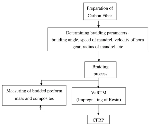
and low shrinkage [4]. Carbon fibers were braided using a circular braiding machine (Kokubun Limited, 40Z048C). This research consists of two section of experiments, the first set of experiments is internal pressure test (using steel pipe as a mandrel with outer diameter 64 mm and thickness 2 mm,) and the second set of experiments is bending test (using styrene pipe as a mandrel with outer diameter 25 mm). In this thesis, the procedure for the manufacture of braided CFRP composites as described briefly in Figure 1 :
Figure 1 Flow chart for the manufacture of braided CFRP composites
Braiding parameters will affect the final geometry of the braided preform and subsequently the mechanical properties. The Primary parameters: speed of the carrier (m/s), speed of the mandrel v (m/s), and the braiding angle (). The secondary parameter is the radius of mandrel r (m), and the distance of braiding point h (m). An equation relating some of these parameters is given by the simple mathematical relationship :
= 𝑡𝑎𝑛−1(𝜔𝑟
𝑣) ... (1) Where :
: braiding angle (between threads/yarn and vertical direction) (rad) Determining braiding parameters : braiding angle, speed of mandrel, velocity of horn
gear, radius of mandrel, etc Preparation of
Carbon Fiber
Braiding process
VaRTM (Impregnating of Resin)
) CFRP Measuring of braided preform
mass and composites
3 r : radius of the cylindrical mandrel (m)
: average angular velocity of horn gear the machine center (rad/s) v : speed of mandrel (m/s)
Procedures in the VaRTM fabrication process include mold preparation and fabric lay- up, mold sealing and vacuuming, resin preparation at 30 C and impregnation into the mold, drying the composite at a curing temperature of 60 C and hold the temperature for 3 hours.
After confirm the composite becomes dry, the sample is released from the mold and polymer foam removed with limonene liquid. After VaRTM, it is obtained the CFRP specimen for internal pressure test and bending test.
3. Experimental Study on Hoop Stress Affecting Braided Carbon Fiber Reinforced Plastics Subjected to Internal Pressure
This chapter describes a simple method of analyzing the elastic modulus and the hoop stress base on thin cylindrical formula [5]. As shown in Figure 2, CFRP as the outer layer has an elastic modulus E1 and thickness t1, whereas steel as the inner layer has an elastic modulus E2 and thickness t2.
Figure 2 Schematic of a cylindrical specimen showing the dual layer construction.
If the contact pressure Pm is defined as an indeterminate constant force, the outer cylinder has internal pressure Pm and the inner ring receives internal pressure P-Pm. Because they are thin rings subjected to internal pressure and D is the diameter of the ring for the displacement conditions (assuming the increase in both diameters is the same, D1 = D2), the elastic modulus and the hoop stress can be calculated, the formula is expressed as:
𝜎1 = 𝐷
2𝑡1𝑃𝑚 = ( 𝐸1
𝐸1.𝑡1+𝐸2.𝑡2)𝑃𝐷
2 ... (2) 𝜎2 = 𝐷
2𝑡2(𝑃 − 𝑃𝑚) =𝐸 𝐸2
1.𝑡1+𝐸2.𝑡2 𝑃𝐷
2 ... (3)
4 𝐸1 = 𝑃𝐷
𝜀1 2 𝑡1−𝑡2𝐸2
𝑡1 ... (4) ) 𝐸3 = 𝑡1
𝑡1+𝑡2𝐸1+ 𝑡2
𝑡1+𝑡2𝐸2 ... (5) ) Where:
E1 : Elastic modulus of CFRP (GPa).
E2 : Elastic modulus of steel (GPa).
E3 : Elastic modulus of composite (GPa).
P : Internal pressure of CFRP-Steel obtained from experiment (MPa).
1 : Hoop stress of CFRP (m).
2 : Hoop stress of steel 2 mm or SS t2 (m).
Table 1 shows the construction details of the test specimens for the first set of experiments (internal pressure test); it can be shown the fiber volume fraction increases as the braiding angle or the number of layers increased.
Table 1 Summary of construction details of the internal pressure test specimens Name of
specimen
Number of layers
Braiding angle, [°]
Outer diameter, D [mm]
Mass of specimen, [g]
Fiber volume fraction, Wf [%]
N2-60 2 60 65.2 870 33.0
N3-45
3
45 65.7 900 43.6
N3-60 60 66.2 960 48.6
N3-75 75 67.9 1020 51.7
N4-60 4 60 66.8 960 50.2
SS t2 64.0 850
SS t5 70.0 2230
From the internal pressure results, it show that as the braiding angle increased (45, 60, and 75), the direction of the fibers became closer to the hoop stress direction and the fiber volume fraction increases. So that, the specimen tended to be stable and able to resist the internal pressure. As a result, increasing the braiding angle can increase the average elastic modulus of CFRP. At the other hand, as the number of layer increased (2,3, and 4 layers), the fiber volume increases. The specimen tends to be stable and able to resist the internal pressure.
As a result, Increasing the number of layer can increase the average elastic modulus of CFRP.
From the elastic modulus results, hoop stress when internal pressure 20 MPa is calculated. It is
5
found that, when CFRP is added to a steel pipe (SS t2), the hoop stress in the steel pipe can be reduced. It can be seen, as the braiding angle and the number of layers increased, the hoop stress can be reduced. At the other hand, N3-75 (75 in 3 layers) has 54 percent lighter weight than SS t5 and the hoop stress only increases 58 % than SS t5, it can be concluded the N3-75 has comparable (proportional) pressure resistance with SS t5. Table 2 shows the results of the elastic modulus and the hoop stress on various braided preforms of CFRP.
Table 2 Summary of hydraulic test with applied pressure of 20 MPa
Type of Thickness Elastic Modulus Hoop Stress Hoop Stress Unit Hoop
Specimen of CFRP CFRP CFRP Steel Stress
t1 [m] E1 [GPa] σ1 [MPa] σ2 [MPa] σav [MPa]
N3-45 0.00085 61 84 284 211
N2-60 0.0006 58 83 295 231
N3-60 0.0011 72 94 268 194
N4-60 0.0012 93 114 252 188
N3-75 0.0020 122 120 203 152
SS t2 0.002 320
SS t5 0.005 128
4. Study the Effect of Braided Structure on The Bending Properties of Carbon Fiber Reinforced Plastics (CFRP)
This chapter concerns with the flexural (bending) properties of CFRP braided structures investigated under three point bending load. Their bending modulus and maximum load of each configuration were compared and discussed. Table 3 shows a list of specimens for the second set of experiments (three point bending test):
Table 3 Characteristic of specimens Name of
specimen
Axial Yarn
Number of layers
Braiding angle, [°]
Outer diameter, D [mm]
Fiber volume fraction, Wf [%]
N1-45
Not-Exist (N)
1 45 26.5 31.4
N2-45 2 45 26.6 43.7
N3-45 3 45 27.1 52.7
N2-15 2 15 26.5 34.3
N2-60 2 60 27.1 47.4
A2-45 Exist (A) 2 45 27 48.6
6
In general, different braided structure influenced the distribution of strain values and their load. After the test, each of specimens was observed, it is found that deformation at the center of specimens, with fiber break and crack on the matrix. Table 4 shows the results of bending modulus (E) and maximum load (Pmax) on various braided preforms of CFRP.
Table 4 Overview the result of three point bending test Name of
specimen
Axial Yarn
Number of layers
Braiding angle, [°]
Maximum load, Pmax [N]
Bending modulus, E [GPa]
N1-45
Not-Exist (N)
1 45 115.6 8.4
N2-45 2 45 342.7 16
N3-45 3 45 645.4 20.8
N2-15 2 15 313.5 26.6
N2-60 2 60 647.6 9.9
A2-45 Exist (A) 2 45 646.4 56.3
In terms of the different structure, as the number of layers increased (1,2, and 3 layers), the fiber volume fraction of the CFRP increases so that many fibers can distribute the load [6].
As a result, the elastic modulus and the maximum load increased. At the other hand, as the braiding angle decreased (60, 45, and 15), the direction of the fibers became closer to the axial direction so that the fibers can withstand the tensile stress. As a result the bending modulus increased. In contrast, as the braiding angle increased, fiber volume fraction increases so that the maximum load increased. The addition of axial yarn caused many fibers at 0°
braiding angle so that the fibers can withstand the tensile stress. As a result, when axial yarn is added, the bending modulus and maximum load increased.
5. Conclusion
The braided CFRP has been widely used as a structure in vehicles, construction, sports equipment, because of their high strength and lightweight. At the other hand, determining the mechanical properties of composite structures is essential to be applied by its requirements. In this study, a simple approach was used to evaluate the elastic modulus and hoop stress on combinations thin steel cylinders and braided CFRP subjected to internal pressure. From the internal pressure test results show that increasing the braiding angle and the number of layers can increase the elastic modulus of CFRP and addition of CFRP on steel cylinder can decrease the hoop stress. The addition of CFRP to the steel also provided a comparable pressure
7
resistance to steel specimens of the same weight. In terms of the bending test, as the braiding angle decreased the direction of fibers became closer to the axial direction, so that the bending modulus increased. The maximum load value increased with the increasing of fiber volume fraction as the braiding angle and the number of layers increased. By adding the number of layers and axial yarn at composites can also increase the bending modulus and maximum load.
8
REFERENCE
[1]
[2]
[3]
[4]
[5]
[6]
Fraga Jeff, “Boeing 787 From The Ground Up”, (2006) AERO Magazine,17-23.
The Advanced Stitching Machine: Making Composite Wings of The Future”, (1997) NASA Facts Hampton (VA): Langley Research Center.
Smallman R.E, Bishop J. R, “Modern Physical Metallurgy and Materials Engineering”, (1997) Elsevier Science Ltd.
Kaw A. K., “Mechanics of composite materials” (1997) CRC press.
Shigley J E, Budynas R G, Nisbett J K, “Shigley’s Mechanical Engineering Design 9th Edition”, (2011) Published by McGraw-Hill, ISBN: 978-0-07-352928-8.
Potluri P, Manan A, Francke M, Day RJ, “Flexural and Torsional Behaviour of Biaxial and Triaxial Braided Composite Structures”, (2006) Composite Structures, 75, 377–386.

![Table 1 Summary of construction details of the internal pressure test specimens Name of specimen Number of layers Braiding angle, [°] Outer diameter, D [mm] Mass of specimen, [g] Fiber volume fraction, Wf [%] N2-60 2 60 65.2 870 33.0 N3](https://thumb-ap.123doks.com/thumbv2/123deta/5642307.2003609/7.892.109.789.558.863/summary-construction-internal-pressure-specimens-specimen-braiding-diameter.webp)

![Table 4 Overview the result of three point bending test Name of specimen Axial Yarn Number of layers Braiding angle, [°] Maximum load, Pmax [N] Bending modulus, E [GPa] N1-45 Not-Exist (N) 1 45 115.6 8.4 N2-45 2 45 342.7 16 N3-45 3 45 6](https://thumb-ap.123doks.com/thumbv2/123deta/5642307.2003609/9.892.96.804.281.517/overview-bending-specimen-number-braiding-maximum-bending-modulus.webp)
