The large helical device (LHD) Thomson scattering system measures electron temperature and density profiles of LHD plasmas. The original LHD Thomson scattering system has a backward scattering configuration in which the scattering angle is 167o.1, 2) In the original design, laser pulses are absorbed by a beam dump after traveling plasma.
We removed the beam dump and added a beam returning mirror and an optical delay path of 30 m as shown in Fig.1.
The laser beam is reflected by the mirror and runs through again in the LHD plasma. Then we can observe the Thomson scattering light twice per pulse. In the second observation, we measure the Thomson scatting signals from the forward scattering configuration in which the scattering angle is 13o (=180o – 167o). The Thomson scattering spectra from them significantly differ because the scattering angle of the first path differs from the second one significantly. By utilizing the feature, we can extend the measurable electron temperature range without any modification of polychromators. The original LHD Thomson scattering system has been optimized to the temperature range of 50 eV – 10 keV. In the forward scattering configuration, the LHD Thomson scattering system is expected to be able to measure electron temperatures from 1 keV to more than 50 keV.
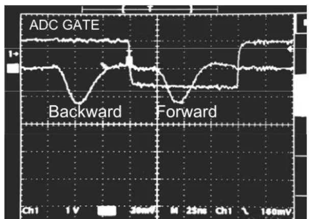
In the 16th LHD experiment campaign, we tried electron temperature measurements using the forward scattering system and successfully observed forward scattering signals. Figure 2 shows an example of the backward and forward Thomson scattering signals. The leading and following pulses are backward and forward scattering signals respectively. Since the optical delay path was installed, the two signals are observed separately.
Figure 3 shows comparisons of electron temperatures and densities for a spatial point obtained from the backward and forward scattering measurements. The electron temperatures show good agreements, and typical differences are within 10 %. Apparent electron densities measured from the forward scattering configuration were smaller than those from the backward scattering configuration by ~1/2. The difference will be caused mainly from misalignment of the forward scattering beam path. Accurate and reliable beam alignment of the forward scattering system is an issue to be solved in the next experiment campaign.
In summary, we succeed the first measurement of electron temperature and density using the forward scattering system in the 16th LHD experiment campaign.
We are planning further improvements of it.
1) K. Narihara, et al.: Rev. Sci. Instrum., 77, 1122 (2001).
2) I. Yamada, et al.: Fusion Sci. Tech., 58, 345 (2010).
Fig.1. Schematic diagram of the backward and forward scattering configuration of the LHD Thomson scattering.
Fig.2. Waveform of the backward and forward scattering signals detected by a wavelength channel in a polychromator. Upper square wave is the gate pulse for analog-to-digital converters.
Comparison of FS and BS: #116036, Poly#053 / R = 3.503 [m]
4 6
Time [sec]
0 2
Te [eV]
Backward Forward
Comparison of FS and BS: #116036, Poly#053 / R = 3.503 [m]
4 6
Time [sec]
0.0 0.2 0.4 0.6 0.8 1.0
ne [arb]
Backward Forward
Fig.3. Comparison of electron temperatures (upper) and densities (lower) from the backward and forward scattering configurations.
Backward Forward
ADC GATE
61
§9. Initial Result of the Forward Scattering Measurement in the LHD Thomson Scattering System for High Electron Temperature Experiments
Yamada, I., Yasuhara, R., Funaba, H., Narihara, K., Kohmoto, T., Hayashi, H.,
Hatae, T., Yatsuka, E., Tojo, H. (JAEA), Yoshikawa, M. (PRC, Univ. Tsukuba), Minami, T. (IAE, Kyoto Univ.)