INVITED PAPER
Special Section on Ambient Intelligence and Sensor NetworksImage Sensor Based Visible Light Communication and Its Application to Pose, Position, and Range Estimations
Takaya YAMAZATO†a)andShinichiro HARUYAMA††,Fellows
SUMMARY This study introduces an image sensor based visible light communication (VLC) and its application to pose, position, and range esti- mations. There are two types of visible-light receiver: a photodiode and an image sensor. A photodiode is usually used as a reception device of VLC, and an image sensor consisting of a large number of pixels can also be used as a VLC reception device. A photodiode detects the signal intensity of incoming light, while an image sensor not only detects the incoming signal intensity but also an accurate angle of arrival of light emitted from a visible light transmitter such as a white LED light. After angles of arrival of light are detected by an image sensor, positioning and data reception can be per- formed. The ability of an image sensor to detect an accurate angle of arrival will provide attractive applications of VLC such as pose, position calcula- tion, and range estimation. Furthermore, because the image sensor has the ability to spatially separate sources, outdoor positioning even with strong sunlight is possible by discarding the associated pixels of noise sources.
key words: visible light communication, image sensor, pose estimation, positioning, range estimation
1. Introduction
Visible light communication (VLC) has been recently de- veloped as a method of optical wireless communication that uses solid-state lighting devices such as semiconductor light-emitting diodes (LEDs). Because LEDs can be modu- lated at high speeds that are undetectable to the human eye, VLC provides the dual functionality of lighting and commu- nication [1], [2].
Growing research trend of VLC may be verified from the numbers of published paper related to VLC. In IEEE Xplore, 53 (2013), 29 (2012) and 13 (2011) journal papers are found and 3 (2013), 5 (2012), and 1 (2011) in IEICE I-Scover. Optical Wireless workshop has been successfully held since 2011 in conjunction with IEEE GLOBECOM, and the special issues on VLC were published in IEEE Com- munication Magazine in Dec. 2013 and again in July 2014.
VLC standards are already available. The first VLC specification standard was released from JEITA in con- junction with Visible Light Communication Consortium (VLCC) in 2007. Later in 2008, VLCC released their first specification standard adopting and expanding the IrDA physical layer. IrDA transceiver transmission wavelength (IrDA physical layer) is expanded to accommodate the visi-
Manuscript received April 15, 2014.
Manuscript revised May 16, 2014.
†The author is with Nagoya University, Nagoya-shi, 464-8603 Japan.
††The author is with Keio University, Yokohama-shi, 223-8526 Japan.
a) E-mail: [email protected] DOI: 10.1587/transcom.E97.B.1759
ble light wavelength. By adapting this specification, the ex- isting IrDA optical modules can be used for VLC data trans- mission with slight modification. In January 2009, IEEE 802.15 (Wireless Personal Area Networks) Task Group 7 (Visible Light Communication) has been launched and in 2011, they have completed a PHY and MAC standard for VLC [3]. Later in July 2013, a study group for camera com- munications was formed in IEEE 802.15, aiming to stan- dardize VLC for uni-directional, low data rate, short mes- sage broadcasts via LEDs using an image sensor as the re- ceiving device.
VLC is still in the introductory phase, but some unique products are already released, such include Picapicamera by CASIO [4] and Underwater VLC Device by MCR [5].
Commercializing VLC technology are undertaken by many research centers, institutes and consortiums, in Europe, US and in Japan, these include VLCC, LiFi Consortium, Smart Lighting Engineering Research Centre, UC-Light Center [6].
The reason for such trend is that VLC provides sev- eral advantages [7]. Because the transmitters, or LED light sources, are designed for lighting purposes, they usually have high radiation power. In other words, the signal-to- noise ratio is high for VLC. The visible light spectrum ex- tends from 400 to 790 THz, and it is not regulated globally.
The large bandwidth (390 THz) provides opportunities for VLC applications.
It is usually accepted that VLC attains data rates of sev- eral Mb/s using a simple on-off keying modulation and a single-element photodiode as a reception device. Such may be enough for VLC startup applications. The data rate may exceed 1 Gb/s by applying more spectrally efficient modula- tion formats [8]. Such high speed VLC suggests that VLC is a strong candidate to resolve a “spectrum deficit” stated by the Federal Communications Commission, especially for indoor wireless usage [9].
Positioning or localization, also known as visible light positioning, is another attractive application of VLC [10].
Though global navigation satellite systems such as GPS, GLONASS, Galileo, and Compass are widely used as navi- gation systems for cars and smartphones, their signals from satellites are unable to reach indoors, resulting in an inabil- ity to detect the positions of users or objects indoors. Con- versely, LEDs that are placed as a ceiling light provide a small personal optical cell, and the isolated LED link de- livers a simple positioning solution by sending positioning information from the LED.
Copyright c2014 The Institute of Electronics, Information and Communication Engineers
nal bandwidth; the modulation bandwidth of the broad- spectrum component is approximately 2 MHz, while for the blue component, it may be equal to 20 MHz.
The above limitations are due to the use of a photodiode as a receiver, because a photodiode receives incoming light and detects its intensity; however it cannot detect the angle of arrival (AOA) of the incoming light.
Alternatively, an image sensor is able to detect the AOA in addition to the intensity of the incoming light. By using image processing to detect and recognize objects, po- sitioning can be integrated. For example, positioning and data reception are easily achieved. It is reported that VLC can achieve centimeter-level accuracy of indoor positioning at low cost [11]. Furthermore, as the image sensor has the ability to spatially separate sources, outdoor positioning is possible by discarding associated pixels of noise sources.
Although image senor has been used in Infrared com- munications, the image size is small and the sensor is mainly designed for communication use [12]. It is not suitable for positioning application. We note, however, that the image sensor used for infrared photography can be used.
In this study, we introduce image sensor based VLC and its application to pose, position, and range estimation.
After starting with an overview of image sensor based VLC in Sect. 2, we introduce the basics of sensor pose estimation and position measurement in Sect. 3. In Sect. 4, we intro- duce three unique applications: pose estimation using lights, application to bridge-shape monitoring, and range estima- tion using phase-only correlation (POC). Finally, in Sect. 5, concluding remarks are presented.
2. Image Sensor Based VLC
An image sensor is a device that converts an optical image into an electronic signal. Image sensors are used in digital cameras, camera modules, video recorders, and other imag- ing devices. An image sensor consists ofn×mpixels ranging from 320×240 (QVGA) to 157,000×18,000 (line scanner).
Each pixel contains a photodetector or photodiode and de- vices for readout circuits. The readout circuits included in pixel devices determine the sensor conversion gain, which is the output voltage per electron collected by photodiode.
The readout speed determines the frame rate, typically 30 frames per second. High frame rates are required for many industrial and measurement applications.
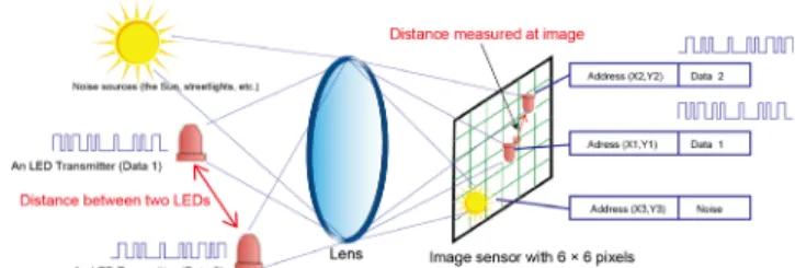
A photodiode is usually used as a reception device of VLC, and an image sensor consisting of various pixels can also be used as a VLC reception device [1], [2]. A specific advantage of the image sensor usage is its ability to spatially separate sources, because of the massive number of pixels
Fig. 1 Image sensor based VLC and positioning.
available.
The ability to spatially separate sources also provides an additional feature to VLC, specifically, the ability to re- ceive and process multiple transmitting sources. Figure 1 shows that the data transmitted from two different LED transmitters can be captured simultaneously.
The output of the image sensor forms a digital elec- tronic representation of the scene. Figure 1 shows that the relative position of two LEDs is projected onto the image sensor. Thus, if the real positions of two LEDs as well as the distance between them are available at the receiver, po- sitioning of the receiver can be performed by triangulation.
While such positioning can be processed by an image sen- sor only (without an aid of VLC), we point out the following advantages of positioning by VLC.
1) Because LEDs can transmit identification numbers (IDs) and other necessary information, no preinstalled data are necessary.
2) Object recognition is much easier because the fast- blinking feature of LEDs is rare in the natural world;
thus, no complex image processing is necessary. Fast object recognition is possible even in real-time and receiver-moving (vehicle-driving) cases.
3) The ubiquity of LEDs yields much available data to per- form localization. Thus, by using only available relevant data and discarding extraneous data, accuracy can be im- proved easily.
3. Basics of Sensor Pose Estimation and Position Mea- surement
In image sensor based VLC, it is possible to compute a sen- sor (camera) pose with computer vision techniques. This is one of the main advantages compared with other communi- cation techniques. Here, we introduce the basis of computer vision for pose estimation and a pose-estimation method combined with computer vision as well as VLC techniques.
3.1 Single-View Geometry
Computer vision is the study of analyzing the geometry of the real world from images captured with a camera. In gen- eral, research issues can be classified into the estimation of the pose of a camera and the reconstruction of the 3D shape of an object (also called 3D modeling) from an image or an
Fig. 2 Single-view geometry.
image sequence. The related research fields of computer vi- sion include image processing, pattern recognition, and ma- chine learning for scene recognition and understanding.
In image sensor based VLC, an image sensor can re- ceive data simultaneously transmitted from multiple lights because each pixel on the sensor is treated as one receiver.
Also, the positions of the lights on the image sensor are ac- quired as feature points and can be used for camera pose es- timation. Extensive literature already exists on camera pose estimation using points [13] because it is a traditional re- search issue. Here, we introduce the basis of single-camera geometry for camera pose estimation. Note that the term
“pose” represents the position and orientation relative to some coordinate system in the field of computer vision.
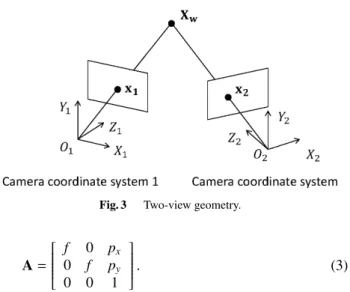
As shown in Fig. 2, camera geometry is described with three coordinate systems: 3D world coordinate system, 2D image coordinate system, and 3D camera coordinate system.
A camera pose is usually defined as the position and orien- tation of the camera coordinate system relative to the world coordinate system. The mathematical representation of the position and orientation is equivalent to the parameters of geometric transformation from the world coordinate system to the camera coordinate system as
X˜c=
R t
0 1
X˜w (1)
where ˜Xc=(Xc,Yc,Zc,1)Tis a homogeneous camera coor- dinate, ˜Xw=(Xw,Yw,Zw,1)Tis a homogeneous world coor- dinate,Ris a 3×3 rotation matrix (orientation), andtis a 3×1 translation vector (position). Therefore, a camera pose is equivalent to [R|t].
The camera coordinate system is defined as the system in which its origin is located at the camera center and the direction ofZcis perpendicular to the image plane from the camera center. The point of intersection of the image plane and theZcaxis is called the principal pointp=
px,py . In the pinhole camera model, a 3D pointXc=(Xc,Yc,Zc)Tin the camera coordinate system is projected onto a 2D pointx
=(x, y)Tin the image coordinate system as (x, y)T=
fXc
ZC +px,fYC
Zc +py T
(2) where f is the focal length of a lens. By making a camera calibration matrixAas
Fig. 3 Two-view geometry.
A=
⎡⎢⎢⎢⎢⎢
⎢⎢⎣
f 0 px
0 f py
0 0 1
⎤⎥⎥⎥⎥⎥
⎥⎥⎦. (3)
The projection of a 3D point in the world coordinate system onto a 2D point in the image coordinate system is described as
x˜ ∼A[R|t] ˜Xw (4)
where ˜x=(x, y,1) is a homogenous image coordinate. This equation is also simplified as
˜
x∼PX˜w (5)
P=A[R|t] (6)
wherePis a 3×4 perspective projection matrix that also represents a camera pose.
To estimate a camera pose by solving the above equa- tions, attaining multiple sets of ˜xand ˜Xwis mandatory. For example,Pis linearly computed from six sets because there are 12 unknown parameters inPand two equations are pre- pared from one set. IfAis known using a camera calibration technique [14], it is possible to compute a camera pose up to four pairs of solutions [15]. Because many solutions under different conditions have been proposed in the literature, the solutions are not limited to the above ones.
3.2 Basis of Triangulation
Triangulation is a method for 3D position measurement of an object in the real world with two known cameras. A 3D point in the world coordinate system is projected onto a 2D point in the image coordinate system. When a 3D point ˜Xw
is projected onto two cameras, this is mathematically de- scribed as
˜
x1∼P1X˜w (7)
˜
x2∼P2X˜w (8)
wherePi is a perspective projection matrix of each camera and ˜xiis a homogeneous image coordinate computed by pro- jecting ˜Xwonto each image plane withPi. ˜x1and ˜x2are con- sidered as correspondences between the two images. The use of two known cameras means thatP1andP2are known.
This is also graphically explained in Fig. 3. In triangulation,
Fig. 4 Pose estimation using lights.
Table 1 List of IDs and world coordinates.
the goal is to compute ˜Xwby finding ˜x1and ˜x2.
4. Application to Pose, Position, and Range Estima- tions
4.1 Pose Estimation Using Lights
It is necessary to acquire multiple sets of a world coordinate and its projected image coordinate for camera pose estima- tion. In image sensor based VLC, such sets are acquired using lights.
Figure 4 shows an overview of pose estimation using lights [16]. Lights are first placed in a target scene and their 3D world coordinates are measured using an electronic dis- tance meter such as a total station. To compute the image co- ordinate of a light and receive its transmitted data, a camera captures the lights at a fixed position because a light should be captured at the same position through an image sequence.
When the transmitted data can include the world co- ordinate of the light, the set of the world coordinate of a light and its projected image coordinate is simply acquired.
However, the size of transmitted data may not be adequate.
Therefore, the transmitted data can be just an ID and the list of the IDs of lights and their world coordinates, as shown in Table 1, should be stored in a computer before. If the number of acquired sets satisfies the condition of pose esti- mation, a camera pose can be computed. Note that the accu- racy of an estimated camera pose depends on the accuracy of the measurement of 3D world coordinates. In the following subsection, we explain an efficient method for computing the image coordinate of a blinking light.
4.2 Application to Bridge Shape Monitoring
Image sensor based VLC works under different types of illu- mination, from daytime to midnight, because a light actively
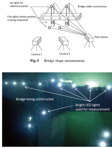
Fig. 5 Bridge shape measurement.
Fig. 6 Snapshot of a bridge being measured.
transmits data by blinking. This feature is convenient for bridge shape monitoring. In general, the shape of a bridge is deformed because the fabric of the bridge dilates and shrinks according to the ambient temperature. When a bridge is built, such deformation should be monitored for the early detection of problems.
Figure 5 shows an overview of bridge shape monitor- ing. On the bridge, two different types of lights are placed:
points for measuring the deformation and points for cam- era pose estimation. The latter points are typically called reference points and should be placed at the points where deformation does not occur.
The monitoring procedure is as follows. From the ref- erence points, the poses of Camera 1 and Camera 2 are first computed. At each camera, the image coordinates of lights and the transmitted data are then computed. By selecting the pixels that send the same data, the corresponding pixels of a light in two images are computed. Such pixels are tri- angulated to compute the 3D position of the light. Figure 6 shows a snapshot of a bridge under construction whose po- sitions are being measured using the technology described here. The positions of the bright LED lights on the bridge are being measured, while the positions of the bright LED lights on the ground and at the pier are measured by a total station before.
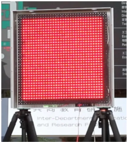
Fig. 7 1024 LED array. Each LED is arrange in square matrix of 32×32.
The size of the LED array is 465 mm×465 mm, with the LED spacing of 15 mm. The LEDs are the same as the actual LED traffic lights in Japan.
4.3 Range Estimation Using Phase-Only Correlation Normally, when we use triangulation, either two transmit- ters and one camera, or one transmitter and two cameras, are used. The longer the distance between two transmitters or two cameras, the better range estimation is obtained. Here, we consider range estimation using two LEDs placed on the edges of an LED array and one camera receiver.
Figure 7 shows the LED array used for the experiment.
Although estimating from an LED array is attractive in some applications, the breadth of LED array is small (465 mm).
Therefore, poor range accuracy is expected because the dis- tance measured at the camera coordinate only considers a small value. In fact, for the LED array shown in Fig. 7, the projected width of the LED array is only 9 pixels at 60 m us- ing a 35 mm lens. In such cases, the range error may reach 3.5 m at a distance of 60 m.
A solution is to estimate the projected width of the LED array in subpixel resolution using POC [17], [18].
Before we discuss the details of POC, we begin with a mathematical equation for estimating range from the pro- jected width of the LED array.
LetLbe a range to be estimated, then we obtainLas [19]
L= f S
Wα, (9)
whereSis the width of the LED array,αis a pixel size of the image sensor inμm, andf is the focal distance of the camera lens. The projected width of the LED array, denoted byW, is the parameter to estimate. BecauseS,α, andfare constants, the accuracy of the distance is controlled byW.
Figure 8 illustrates 3×3 pixels around an LED. The LED overlaps with six pixels. We estimate the position of the LED as the highest luminance pixel in the six pixels.
The estimated center of the LED is considered as the center of pixel shown by a circle, whereas the actual center of the LED is shown by a triangle. As shown, the actual center of
Fig. 8 Captured LED overlap with multiple pixels.
Fig. 9 POC imageG12forf1(m,n) andf2(m,n)=f1(m+τm,n+τn).
the LED is different from the estimated center.
4.3.1 Subpixel Range Estimation Using POC
POC is a pattern-matching algorithm and defined as a mod- ified correlation algorithm such that the amplitude compo- nents of the Fourier-transformed images are replaced with a constant. In general, POC is used for position displacement detection of the same object.
In POC, the position displacement of the two images is reflected by cross-correlation. Let us consider f2(m,n)= f1(m+τm,n+τn) that the original image f1(m,n) is shifted to τmin themdirection andτnin thendirection, respectively, whereτm andτn are consecutive values. Note that pixel- widthWtakes a natural number. If we denoteδmandδnas a small discrete value,τmandτnare given by
τmWm+δm, (10)
τnWn+δn (11)
Then we obtain POC as the following [19]:
G12(r−τm,s−τn) ⎧⎪⎪⎪⎨
⎪⎪⎪⎩
1 r=Wm+δm,s=Wn+δn
ξ(<1) r=Wm,s=Wn
ε rWm,sWn
(12) Figure 9 shows a result of the POC using two images.
Fig. 10 Sinc function approximation of G12(r, s) shown in cross-section of Fig. 8 inndirection.
Table 2 Parameters of high-speed camera (Photron FASTCAM- 1024PCI 100 K).
Unfortunately, POC output is a function of the integer val- ues ofWm andWn, respectively, therefore the accuracy is still limited to the pixel width. Because the actual values of displacement are denoted byτmWm+δmandτnWn+δn
it is essential to estimateδmandδn.
From (11), if we know δm andδn, thenG12(r,s) be- comes one. Moreover, we can approximateG12(r,s) by the sinc function.
G12(r,s)sinc(r+δm)sinc(s+δn) (13) The peak ofG12(r,s) can be obtained by varyingδmandδn. The center of the LED is given by
(Wm+δˆm,Wn+δˆn)= arg max
−1≤δm≤1,−1≤δn≤1
G12(r,s), (14) Where ˆδmand ˆδnare the estimates ofδmandδn, respectively.
Figure 10 shows a cross-section image of Fig. 9 in thendi- rection. The triangle in Fig. 8 expresses the center of the LED.
4.3.2 Experimental Results
We performed experimental measurements in 5 m incre- ments in a static condition, for distances from 20 m to 60 m.
The LED array is shown in Fig. 7, and Table 2 summarizes the parameters of the high-speed camera.
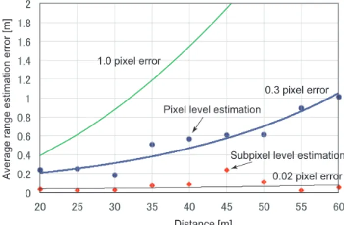
Figure 11 illustrates the average range estimation er- ror levels. The horizontal axis represents the distance be- tween the LED array and the receiver camera, and the verti- cal axis represents the range estimation errors. The graph label “pixel level estimation” represents the conventional range estimation method, whose accuracy is limited to pixel
Fig. 11 Average range estimation error versus distance.
width. The graph label “subpixel level estimation” repre- sents the range estimation error levels using POC, whose accuracy is at the subpixel level. As we confirm from the figure, the curve of “subpixel level estimation” achieves less than 0.3 m estimation error from 20 to 60 m. We note that this corresponds to a 0.02-pixel subpixel estimation accu- racy. In contrast, the curve of the “pixel level estimation”
scheme shows more than 1 m estimation error at 60 m.
5. Conclusions
In this study, we introduced the image sensor based VLC and its application to pose, position, and range estimations.
From the basics of sensor pose estimation and position mea- surement, we showed application examples of accurate sen- sor pose estimation, position measurement for civil engi- neering, and range estimation using POC.
An image sensor is able to spatially separate visible light sources, receive and demodulate optical signals from a visible light transmitter at a pixel position where the opti- cal light is projected, and detect accurate arrival angle of an incoming light. By using the unique characteristics of im- age sensors, applications shown in this study are made pos- sible. For example, the capability of accurate arrival angle detection makes it possible to perform accurate sensor pose estimation and position measurement for civil engineering, and the capability of image processing makes it possible to perform range estimation.
References
[1] S. Haruyama and T. Yamazato, “[Tutorial] Visible light communi- cations,” IEEE International Conference on Communications, June 2011.
[2] T. Yamazato, I. Takai, H. Okada, T. Fujii, T. Yendo, S. Arai, M. An- doh, T. Harada, K. Yasutomi, K. Kagawa, and S. Kawahito, “Image sensor based visible light communication for automotive applica- tions,” IEEE Commun. Mag., vol.52, no.7, pp.88–97, July 2014.
[3] S. Rajagopal, R.D. Roberts, and S.-K. Lim, “IEEE 802.15.7 visible light communication: Modulation schemes and dimming support,”
IEEE Commun. Mag., pp.72–82, March 2012.
[4] http://www.casio-isc.com/en/ [5] http://www.mcrvlc.jp/?lang=english
[6] http://www.marketsandmarkets.com/Market-Reports/visible-light- communication-market-946.html
[7] Harald Haas, “Wirelss data from every light bulb,” http://www.ted.
com/talks/harald haas wireless data from every light bulb [8] M. Ishida, S. Miyauchi, T. Komine, S. Haruyama, and M.
Nakagawa, “An architecture for high-speed parallel wireless visible light communications system using 2D image sensor and LED trans- mitter,” Proc. International Symposium on Wireless Personal Mul- timedia Communications (WPMC’05) (CD-ROM), pp.1523–1527, 2005.
[9] L. Grobe, A. Paraskevopoulos, J. Hilt, D. Schulz, F. Lassak, F.
Hartlieb, C. Kottke, V. Jungnickel, and K. Langer, “High-speed visi- ble light communication systems,” IEEE Commun. Mag., pp.60–66, Dec. 2013.
[10] J. Armstrong, Y. Sekercioglu, and A. Neild, “Visible light position- ing: A roadmap for international standardization,” IEEE Commun.
Mag., pp.68–73, Dec. 2013.
[11] A. Jovicic, J. Li, and T. Richardson, “Visible light communication:
Opportunities, challenges and the path to market,” IEEE Commun.
Mag., pp.26–32, Dec. 2013.
[12] J.M. Kahn, R. You, A.G. Weisbin, B.K. Teik, and A. Tang, “Imaging diversity receivers for high-speed infrared wireless communication,”
IEEE Commun. Mag., pp.88–94, Dec. 1998.
[13] R. Szeliski, Computer vision: Algorithm and applications, Springer, 2011.
[14] Z. Zhang, “A flexible new technique for camera calibration,” IEEE Trans. Pattern. Anal. Mach. Intell., pp.1330–1334, 2000.
[15] D. Nister, “A minimal solution to the generalised 3-point pose prob- lem,” Proc. IEEE Computer Society Conference on Computer Vi- sion and Pattern Recognition, pp.560–567, 2004.
[16] H. Uchiyama, M. Yoshino, H. Saito, M. Nakagawa, S. Haruyama, T. Kakehashi, and N. Nagatomo, “Photogrammetric system using visible light communication,” Proc. 34th Annual Conference of the IEEE Industrial Electronics Society, pp.1771–1776, 2008.
[17] K. Takita, T. Aoki, Y. Sasaki, T. Higuchi, and K. Kobayashi, “High- accuracy subpixel image registration based on phase-only correla- tion,” IEICE Trans. Fundamentals, vol.E86-A, no.8, pp.1925–1933, Aug. 2003.
[18] H. Foroosh, J.B. Zerubia, and M. Berthod, “Extension of phase correlation to subpixel registration,” IEEE Trans. Image Process., vol.11, no.3, pp.188–200, March 2002.
[19] A. Ohmura, T. Yamazato, H. Okada, T. Fujii, T. Yendo, and S. Arai,
“Accuracy improvement by phase only correlation for distance esti- mation scheme for visible light communications using an LED array and a high-speed camera,” Proc. 20th World Congress on Intelligent Transport Systems, Oct. 2013.
Takaya Yamazato is a professor at the Institute of Liberal Arts and Sciences, Nagoya University, Japan. He received the Ph.D. de- gree from Department of Electrical Engineer- ing, Keio University, Yokohama, Japan, in 1993.
From 1993 to 1998, he was an Assistant Pro- fessor in the Department of Information Elec- tronics, Nagoya University, Japan. From 1997 to 1998, he was a visiting researcher of the Re- search Group for RF Communications, Depart- ment of Electrical Engineering and Information Technology, University of Kaiserslautern. In 1998, he gave a 1/2-day tuto- rial entitled “Introduction to CDMA ALOHA” at Globecom held in Sydney Australia. Since then, he has been serving as a TPC member of Globecom and ICC. In 2006, he received the IEEE Communication Society 2006 The Best Tutorial Paper Award. He served as a co-chair of Wireless Commu- nication Symposia of ICC2009 and he was a co-chair of Selected Areas in Communication Symposia of ICC2011. From 2009–2010, he was an editor in chief of Japanese Section of IEICE Transaction on Communications. His research interests include visible light communication, satellite and mobile communication systems, and ITS.
Shinichiro Haruyama is a professor at The Graduate School of System Design and Man- agement, Keio University, Yokohama, Japan.
He received an M.S. in engineering science from University of California at Berkeley in 1983 and a Ph.D. in computer science from the Univer- sity of Texas at Austin in 1990. He worked for Bell Laboratories of AT&T and Lucent Tech- nologies, U.S.A. from 1991 to 1996, and for Sony Computer Science Laboratories, Inc. from 1998 to 2002. He then joined Department of In- formation and Computer Science, Faculty of Science and Technology, Keio University in 2002, and moved to a The Graduate School of System Design and Management, Keio University in 2008. He is a chair of Visible Light Communication Association. He is a fellow of IEICE. His research inter- ests include visible light communication, wireless communication, system design automation, and integrated circuit design.