Thesis Abstract
No.
Registration Number
“KOU” □ “OTSU”
No. *Office use only Name Chinnapat Sertthin Thesis Title
An Indoor Positioning Architecture Based on Visible Light Communication and Multiband Received Signal Strength Fingerprinting
Thesis Summary
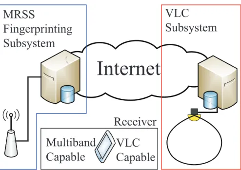
In this dissertation, we focus on developing a new indoor positioning architecture that does not require any extra infrastructure and has long life cycle. The study approach focuses on the following technologies; visible light communication (VLC) that uses next generation light bulb as transmitter and multiband received signal strength (MRSS) fingerprinting created from existing wireless infrastructure.
Chapter 1 presents an introduction to the localization technology. First, we explain the need of indoor positioning system, including the key performance evaluation index for positioning system. Then, we move on to introduce our proposed architect, which does not require any modification on the core equipments after being implemented.
We deploy machine learning algorithms in both subsystems to ensure the system involvement throughout the system.
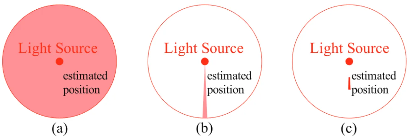
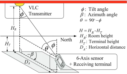
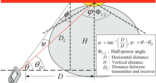
Chapter 2 presents VLC based positioning subsystem architecture. The detailed investigation on characteristics of VLC based positioning subsystem is presented in this chapter. Based on system characteristic, field of view (FOV) limit and sensitivity limit, we proposed a switching estimated receiver position (SwERP) scheme that can improve positioning accuracy more than 80 % over the conventional VLID system.
Chapter 3 presents an additional module that help eliminating sensitivity limit requirement to enable SwERP scheme. To be specific, nearest transmitter classification (NTC) method based on optical orthogonal code (OOC) is used instead of relying on the presence of sensitivity limit. Moreover, based on FOV limit we propose a physical layer simulation model as a reference for future simulation purpose.
Chapter 4 is the proposal on deploying frequency diversity in received signal strength (RSS) fingerprinting, denoted as multiband received signal strength (MRSS) fingerprinting, which can improve positioning accuracy of the conventional RSS fingerprinting system over 50%. The characteristics and parameters that affect the positioning accuracy are provided in this chapter.
Chapter 5 concludes this dissertation. Design and implementation guidelines are suggested based on the performance study of the proposed indoor positioning architecture. The future possible developments based on this proposed architecture are also explained.
by
A dissertation submitted in partial satisfaction of the requirements for the degree of Ph.D. in Engineering
Graduate School of Science and Technology Keio University, Yagami Campus
Keio University
1858
CA
LAMVS GLADIO FORTIOR
Visible Light Communication and Multiband Received Signal Strength Fingerprinting
August 2011
Chinnapat Sertthin
Copyright 2011 by
Chinnapat Sertthin
Abstract
An Indoor Positioning Architecture Based on Visible Light Communication and Multiband Received Signal Strength Fingerprinting
by
Chinnapat Sertthin
Doctor of Philosophy in Engineering Keio University, Yagami Professor Tomoaki Ohtsuki, Chair
In the recent years positioning has become basis for a number of emerging technologies such as wide area ubiquitous network, robotics, cognitive radio and LTE release 9+. Location information can provide additional context for location-aware mobile stations. The mean- ing and the relevance of data can be interpreted differently as the mobile station’s location changes with time. The outdoor localization can be achieved by the assist of GPS; neverthe- less, GPS accuracy in indoor environment is highly degraded due to the effects of multi-path component and obstacles. Numerous of indoor positioning systems have been proposed;
such as ultra wide band (UWB) system, Pseudolite that requires extra infrastructures and high complexity transceiver for synchronization due to the property of time-of-arrival (TOA) method. Therefore, indoor location determination for mobile stations imposes a significant challenge for the success of ubiquitous and pervasive wireless computing.
In this dissertation we focus on developing a new architecture that could be an eco-friendly solution for indoor positioning system that does not require any extra infrastructure, has long life cycle, and does not generate extra carbon footprint during the implementation. The proposed platform must be able to access from anywhere, anytime, anyone and anything.
We focus on the high compatibility function of the proposed platform, of which can be seamlessly implemented on the existing infrastructure. In the approach we focus on the following technologies, visible light communication (VLC) and multiband received signal strength (MRSS) fingerprinting. The studied highlight system characteristic, difficulty and breakthrough.
To my late grandmother who wished to see me complete my study, and my family for all of the love and support.
Contents
List of Figures v
List of Tables ix
1 Introduction 1
1.1 Background of Indoor Positioning Systems . . . . 2
1.2 Principle of Localization Technology . . . . 4
1.2.1 Access Methods . . . . 4
1.2.2 Measurement Types . . . . 6
1.2.3 Techniques in Positioning System . . . . 6
1.2.4 Limitations . . . . 10
1.3 Common Components of Indoor Positioning Systems . . . . 12
1.3.1 Sensing Technologies . . . . 13
1.3.2 Related Indoor Positioning Systems . . . . 14
1.4 Signal Characteristics . . . . 15
1.4.1 Reflection . . . . 16
1.4.2 Diffraction . . . . 16
1.4.3 Transmission . . . . 18
1.4.4 Scattering . . . . 18
1.4.5 Similarity and Differences . . . . 19
1.5 Motivation of This Research . . . . 20
1.6 Proposed Positioning System Architecture . . . . 20
1.6.1 Visible Light Communication Subsystem . . . . 21
1.6.2 MRSS Fingerprinting Subsystem . . . . 24
1.6.3 Positioning Engine (Machine Learning) . . . . 26
1.7 Advantage and Disadvantage of Each Subsystem . . . . 28
1.8 Approaches and Contributions . . . . 28
1.9 Organization . . . . 30
2 VLC Based Positioning Subsystem Architecture 34
2.1 Proposed Infrastructure . . . . 34
2.1.1 Visible Light Communication (VLC) . . . . 35
2.1.2 Visible Light Identification System (VLID) . . . . 36
2.1.3 6-Axis Sensor . . . . 38
2.1.4 Positioning Display System (PDS) . . . . 39
2.2 Proposed System Characterestics . . . . 41
2.2.1 Positioning Characteristics . . . . 41
2.2.2 FOV Limit . . . . 42
2.2.3 Sensitivity Limit . . . . 44
2.3 Experimental Setup . . . . 47
2.3.1 Receivable Range . . . . 49
2.3.2 Positioning Estimation . . . . 49
2.3.3 Information Fusion and Integration . . . . 50
2.3.4 Angulations Conversion . . . . 50
2.4 Proposed Positioning Modules . . . . 52
2.4.1 General Orientation Sensor’s Information (GOSI) . . . . 53
2.4.2 Switching Estimated Receiver Position (SwERP) . . . . 54
2.5 Performance Evaluation . . . . 55
2.5.1 Azimuth Angulations Error (βErr) . . . . 55
2.5.2 Receivable Range Investigation Analysis . . . . 56
2.5.3 Relationship Between Tilt Angulations and Estimated Receiver Position 61 2.5.4 Achievable Accuracy . . . . 64
2.5.5 Uncertainty of Terminal’s height (∆H) . . . . 66
2.6 Conclusion . . . . 67
3 Enhancement Modules for VLC Based Positioning Subsystem 69 3.1 Nearest Transmitter Classification (NTC) Method . . . . 69
3.1.1 Received Optical Power Based NTC (N T COP) Method . . . . 70
3.1.2 Optical Orthogonal Code (OOC) . . . . 71
3.1.3 System Description . . . . 73
3.1.4 Proposed OOC Based NTC (N T COC) Method . . . . 76
3.1.5 Performance Evaluation . . . . 78
3.2 Physical Layer Simulation Model . . . . 80
3.2.1 Geometric Optics : GO . . . . 80
3.2.2 Proposed Method . . . . 81
3.2.3 Rotation Matrix . . . . 82
3.2.4 Support Vector Machines . . . . 83
3.2.5 System Model . . . . 84
3.2.6 Performance Evaluation . . . . 85
3.3 Conclusion . . . . 89
4 MRSS Fingerprinting Subsystem Architecture 91
4.1 Basic Infrastructure . . . . 91
4.1.1 Cognitive Radio . . . . 92
4.1.2 Existing Infrastructure . . . . 92
4.1.3 Principle of MRSS Fingerprinting . . . . 94
4.2 Wireless Chanel Characteristics . . . . 96
4.2.1 Empirical Model . . . . 96
4.2.2 Ray-Tracing . . . . 99
4.3 Proposed System . . . 100
4.3.1 Characteristic Between LOS and NLOS . . . 100
4.3.2 KNN MRSS Fingerprinting . . . 101
4.3.3 Frequency Correlation Analysis . . . 102
4.3.4 Correct Estimation Probability Analysis . . . 103
4.4 Experimental Setup . . . 103
4.4.1 LOS Environment . . . 106
4.4.2 NLOS Environment . . . 106
4.5 Performance Evaluation . . . 106
4.5.1 RSS Time Series . . . 106
4.5.2 MRSS Fingerprint . . . 111
4.5.3 Frequency Correlation . . . 111
4.5.4 Correct Estimation Probability . . . 111
4.5.5 Achievable Accuracy . . . 115
4.6 Conclusion . . . 117
5 Conclusion and Future Development 119 5.1 Contributions . . . 120
5.2 Future Development of The Proposed Architecture . . . 120
Bibliography 122
List of Figures
1.1 Rho-Theta location measurement configuration . . . . 7
1.2 Theta-Theta location measurement configuration . . . . 8
1.3 Rho-Rho location measurement configuration . . . . 8
1.4 Geometry of TDOA location method . . . . 10
1.5 Illustration of time resolution (τclk) . . . . 11
1.6 A general wireless positioning system functional block diagram . . . . 13
1.7 Specular reflection with source image . . . . 16
1.8 2D of view wedge diffraction geometry . . . . 17
1.9 Reflection and scattering from a rough surface. . . . 19
1.10 Approximate timeline of the mobile communications standards landscape.[25] 20 1.11 The proposed lifetime indoor positioning solution architect block diagram, each subsystem can either work separately or collaboratively. . . . 21
1.12 Estimated position by (a) only data from VLID, (b) data from VLID and 6- axis sensor (c) data from VLID, 6-axis sensor and switching estimated position technique. . . . 22
1.13 Visible light communication based positioning system . . . . 23
1.14 Simulation of (a) instantaneous RSS (b) RSS fingerprinting of 2.4 GHz band in LOS environment (30 × 50 meter), based on log-normal distribution with 4 transmitters located outside at each corner of the simulation area. . . . 24
1.15 Multiband received signal strength based positioning system . . . . 26
1.16 A machine learning diagram . . . . 27
1.17 Illustration of the proposed architecture. . . . 29
1.18 The overall structure of this dissertation. . . . 33
2.1 Visible Light ID Frame Construction. . . . 35
2.2 Signal Waveform of SC-4PPM. . . . 37
2.3 VLID development kit (Transmitter). . . . 37
2.4 VLID development kit (Receiver). . . . 38
2.5 Outline dimensions of 6-axis sensor AK8976A. . . . 39
2.6 Log format of 6-axis sensor AK8976A. . . . . 40
2.7 GUI of VLC based indoor positioning system (Data analytical module). . . . 40
2.8 GUI of VLC based positioning system (Data acquisition module). . . . 41 2.9 Position is estimated from Tilt and Azimuth angulations data from 6-axis
sensor. . . . 42 2.10 An illustration of Tilt angulations plane. ERP A shows the line-ofsight, ERP
B and C are the nearest and furthest position from the transmitter. . . . 43 2.11 An illustration of incident angle of normal light source (ψ) and transmitter’s
half-power angle (Φ1/2). . . . . 43 2.12 An illustration of transmitter (Tx) and its mirror, which are used in geometric
optic calculation. . . . 45 2.13 Illustration of difference between FOV (ψc) Limit, and Sensitivity (RxS)
Limit. FOV limit is unmodifiable physical attribution of the receiver. On the other hand, sensitivity limit is a property of received optical power (Pr), which is modifiable. . . . 45 2.14 Experimental environment the VLC transmitter is attatached at the ceiling
and the receiver is attached with 6-axis sensor to measured the angulations data. . . . 46 2.15 Experimentation on error distance estimation, 44 oriented positions with ran-
dom tilt angle (ϕ) were experimented. . . . 47 2.16 Illustration of the experiments and simulation procedures, simulation param-
eters are adjusted to fit the configuration of the experiments [41]. . . . . 48 2.17 General architecture for data fusion. . . . . 50 2.18 Experimented log file of 6-Axis sensor, the first three columns show the sam-
ples acquired time (hour: min: second), which is used as fusion indicator with data from VLC based positioning GUI. . . . 51 2.19 Experimented data from VLC based positioning GUI. The first column shows
experimented order, where second and third show coordination of experimentd positions. Column four to six show the samples acquired time (hour: min:
second). . . . 51 2.20 Angulations conversion, the data from 6-axis sensor is mapped in to angle
reference with VLC transmitter. . . . 52 2.21 Position is estimated from receivers ψc, ϕ and β from 6-axis sensor. . . . . . 53 2.22 Azimuth (βErr) error distribution analysis. . . . 56 2.23 Positions that azimuth error occur higher than the investigated value (100, 75
and 50 degree). . . . 57 2.24 Comparison of the relationship between terminal’s tilt angle (ψc = 25, 17.5
and 10 degree) and furthest receivable point (in the case of effects from FOV only, effects from channel DC gains, and experimental results, respectively). . 58 2.25 Illustration of FOV Limit of ψc = 25, 17.5 and 10 degree with RXS = 16 nW. 59 2.26 Illustration of Sensitivity Limit of RXS = 16, 20 and 24 nW withψc = 25o. . 59 2.27 Relationship of RMSED among estimated receiver positions and tilt angle
(under receiver’s FOV = 25,17.5, 10 degree configuration). . . . 60
2.28 Illustration of switching angle (ϕS) calculation, derived from intersection point of estimated receiver position A and C polynomial 6th order trend line of
receiver’s FOV = 25, 17.5, 10 degree configuration. . . . . 61
2.29 Illustration of improper switching angle (ϕI) and switching error of receiver’s FOV = 25 degree configuration. . . . 62
2.30 Comparison of acheivable RMSED among utilized tilt angles as switching angle (FOV=25, 17.5, 10 degree). . . . 63
2.31 Effect of Azimuth angulations error on achievable RMSED of each positioning scheme (ψc =25, 17.5, 10 degree). . . . 65
2.32 Cumulative distribution function of error distance from receiver’s ψc = 25, 17.5 and 10 degree configuration. . . . 66
2.33 Effect of terminals height uncertainty on achievable RMSED of each position- ing schemeψc = 25, 17.5 and 10 degree configuration. . . . 67
3.1 Block diagram of the modified VLC transceiver for the proposed NTC method. 75 3.2 Simulation environment with the dimension of 6 m× 12 m × 3 m. . . . . . 75
3.3 Time resolution (τclk) and its relationship with Time-of-Flight (τfk). . . . 77
3.4 An impact of oversampling (Oc) on auto-correlation (θXX) function. . . . 78
3.5 An illustration of oversampling ratio (Oc) and correctly classified nearestTx. 79 3.6 Performance ofN T COC and N T COP in different TSNRs. . . . 79
3.7 An illustration of A) 3D cone function B) All possible conic sections and conditions . . . . 82
3.8 an illustration of simulation environment with the dimension of 6 m × 12 m × 3 m. . . . 84
3.9 Azimuth angulations distribution from simulation environment. . . . . 85
3.10 All possible LOS propagation paths calculated from geometric optics. . . . . 86
3.11 Reflected propagation paths calculated from geometric optics. . . . 86
3.12 Example of FOV’s cone projection and training set for SVM. . . . 87
3.13 An illustration of transmitters and its mirrors. Only transmitter and its mir- rors that classified as inbound region are calculated . . . . 87
3.14 The proposed method percentage of computation over conventional system. In general cases only 20 % of computation is required . . . . 88
3.15 Number of training samples required for SVM to classify each type of conics section . . . . 88
4.1 Infrastructure of MRSS fingerprinting based positioning system. . . . 93
4.2 Multiband RF Fingerprint diagram A) Training phase, MRSS are premea- sured. B) Positioning phase, instantaneous MRSS are compared with MRSS database. . . . . 94
4.3 Frequency time diversity technique. . . 101
4.4 Experimental site configuration at The University of Electro-Communications, Choufu Campus, Advanced Wireless Communication Research Center (AWCC) building, 4th floor; 6 APs was distributed in every room around experimental area. . . 104 4.5 Experimental site configuration at Keio University, Yagami Campus, building
24, 3rd floor, Nakagawa laboratory; 6 APs was distributed in every room around experimental area. . . 105 4.6 Time series of MRSS of both frequency band (2.4 and 5 GHz) at position 11.
The x−axis shows the measured time in second. The y−axis shows received signal strength in dBm. . . 108 4.7 The received signal strength of multiband fingerprint from AP 02 (LOS envi-
ronment). Thex−axis and y−axis shows the location of experimental site in centimeter. The z−axis shows the received signal strength level in dBm. . . 109 4.8 The received signal strength of multiband fingerprint from AP 08. Thex−axis
andy−axis shows the location of experimental site in centimeter. Thez−axis shows the received signal strength level in dBm. . . 110 4.9 Frequency correlation among fingerprint locations, which created from 3 types
of area consisting of 49 locations. . . 112 4.10 Comparison of correct estimation probability at each nearest position, NCEP,
achieved by 4NN classifier utilizing Manhattan (L1) distance. . . 113 4.11 Comparison of correct estimation probability at each nearest position, NCEP,
achieved by 4NN classifier utilizing Euclidean (L2) distance. . . 114 4.12 The mean error from L1 and L2, consequentially, comparison of single band
and multiband, among KNN methods. Thex-axis showsWzof the measured MRSS during training phase. . . . 116 5.1 The future posibility of the proposed indoor positioning architect block dia-
gram, VLC based positioning system is used to calibrate MRSS fingerprinting. 121
List of Tables
1.1 Comparison of advantage and disadvantage among access methods . . . . 5
1.2 Advantages and disadvantages of each subsystem . . . . 28
1.3 Problems of existing schemes and the contribution of the proposed schemes . 31 2.1 Standard of Visible Light ID System . . . . 35
2.2 Parameters of VLC Development Tool Kit . . . . 36
2.3 Specification of 6-Axis Sensor Model AK8976A3 . . . . 38
2.4 Difinition of 6-Axis Sensor AK8976A Log File3 . . . . 39
2.5 Parameters of Experimental Environment . . . . 46
2.6 Parameters of Experimental Environment . . . . 49
2.7 Percentage of Error Under Investigated Angle . . . . 55
2.8 Calculated Switching Angle (ϕS) . . . . 61
2.9 Performance Comparison among Conventional System and the Propose Scheme 64 2.10 N % of Error Distance . . . . 64
3.1 Codeword Sets of an Optimal (341,5,1)−Code [45] . . . . 72
3.2 Simulation Parameters I . . . . 74
3.3 Simulation Parameters II [24] . . . . 76
3.4 Simulation Parameters III . . . . 81
4.1 Model Constants for IEEE 802.16 Model for 2.5 2.7 GHz Band . . . . 97
4.2 Terrain Types . . . . 97
4.3 Training Phase Experimental Parameters of LOS Environment . . . 107
4.4 Training Phase Experimental Parameters of NLOS Environment . . . 107
4.5 Positioning Phase Experimental Parameters of NLOS Environment . . . 107
4.6 Correct Estimation Probability Enhancement at Each Nearest Position Achieved by 4NN Classifier of L1: Manhattan Distance . . . 115
4.7 Correct Estimation Probability Enhancement at Each Nearest Position Achieved by 4NN Classifier of L2: Euclidean Distance . . . 115
4.8 Achievable Accuracy Comparison Among Dist(L1): Manhattan Distance and Algorithms. . . 117
4.9 Achievable Accuracy Comparison Among Dist(L2): Euclidean Distance and Algorithms. . . 117
Acknowledgments
First of all, I would like to show my deepest gratitude to Panasonic Scholarship and Tokio Marine Kagami Memorial Foundation Scholarship for their kind support during my Master and Ph.D degree. I am grateful for the opportunity I was entrusted with, and being able to contribute back to the society through this research. I wish that this research can improve many people’s quality of life, and can be utilized as foundation for location base service very long time. This dissertation has been a long journey. I will not be able to complete this journey with kind support from my colleagues, professors and family.
I wish to acknowledge following group of people whom had utmost helped me on my early research life. Firstly, my previous Professor Masao Nakagawa who spent a lot of time teaching me how to do research, and also giving full authority to me on collaboration work with NTT Innovation Laboratory. Prof. Kobuta and Dr. Kuwano from NTT Network Innovation Laboratory who scarify their time coming to research meeting every month at Keio University. Ass. Prof. Takeo Fujii, Ass. Prof. Ousamu Takyu, and Prof. Yohtaro Umeda who had been assisting me from the very begging until my graduation. My dearest research fellows Dr. Koichi Adachi, thank you very much for teaching me many thing from research to Japanese culture, and previous Nakagawa laboratory’s members especially Ms.
Emiko Tsuji who had help me so much to understand Japanese working culture.
It is very unfortunate that Prof. Nakagawa had early retire due to his health condition. I would like to express my gratitude towards Prof. Tomaki Ohtsuki who had wonderfully take care of me since Professor Nakagawa retirement. I am indebted to his diligence in constantly stimulating me towards the completion of this dissertation. Furthermore, I would also like to express my gratitude for the panel who examined this dissertation, Prof. Iwao Sasase, Prof. Yukitoshi Sanada, and Prof. Hiroshi Shigeno. Their critical review and constructive suggestions added an extra layer of polish to this dissertation.
I would also like to express my appreciation to every professors and staffs in the GCOE program, especially Ms. Maki Adachi, Ms. Yuko Izuta, and Ms. Chinatsu Ichikawa. My fellow Research Assistants (RAs) in the GCOE program, Ass. Prof. Mamiko Inamori, Dr. Maduranga Liyanage, Dr. Alex Fung, and Mr. Oussama Souihli for the stimulating research discussions that helped give my research some perspective. As a member of Ohtsuki Laboratory, I would also like to take advantage of this opportunity to express my thanks towards my other colleagues for their support and encouragement. Particularly, Mr. Jihoon Hong and Mrs. Norharyati Binti Harum for their kind assistances on every aspect. Last but not least, I wish to express my heartfelt thanks to my family who have always been a great source of support and encouragement for me.
Chapter 1 Introduction
In the recent years positioning has become basis for a number of emerging technologies such as wide area ubiquitous network [1], robotics, cognitive radio [2] and LTE release 9+ [3].
Location information can provide additional context for location-aware mobile stations. The meaning and the relevance of data can be interpreted differently as the mobile station’s location changes with time [4]. The outdoor localization can be achieved by the assist of global positioning system (GPS); nevertheless, GPS accuracy in indoor environment is highly degraded due to the effects of multi-path component and obstacles. Numerous indoor positioning systems have been proposed; such as ultra wide band (UWB) system, Pseudolite that requires extra infrastructures and high complexity transceiver for synchronization due to the property of time-of-arrival (TOA) method. Therefore, indoor location determination for mobile stations imposes a significant challenge for the success of ubiquitous and pervasive wireless computing.
Positioning estimation or location determination refers to a process used to obtain loca- tion information of a mobile station (MS) with respect to a set of reference positions within a predefined space. In many literatures, this process is usually also widely known as radiolo- cation [4], position location [5], geolocation [6], location sensing [7], or localization [8]. This dissertation will primarily use positioning but all of these terms are also used interchange- ably throughout the document. A system developed to determine or estimate the location of a targeting unit is called a positioning system. The term positioning system will be used to represent the system throughout this document. An existing infrastructure refers to a previously installed infrastructure for the other purpose such as light bulb for the purpose of illumination, mobile phone infrastructure or wireless local area networks (WLANs), for the purpose of communication. An emerging wireless infrastructure refers to the future wireless technology infrastructure that will be implemented for communication purpose to its sub- scribed user. A set of coordinates or reference points within the predefined space is typically used to indicate the physical location of the entity. For example, an indoor positioning sys- tem may include position information such as a floor number, a room number, and other reference objects to represent an entity’s position.
In this dissertation we focus on developing a new architecture that could be an eco-friendly solution for indoor positioning system that does not require any extra infrastructure, has long life cycle, and does not generate extra carbon footprint during the implementation. The proposed platform must be able to access from anywhere, anytime, anyone and anything.
We focus on the high compatibility function of the proposed platform, of which can be seamlessly implemented on the existing infrastructure. In the approach we focus on the following technologies, visible light communication (VLC) and multiband received signal strength (MRSS) fingerprinting. The studied highlight system characteristics, difficulty and breakthrough solution. First, this chapter presents the background of indoor positioning systems, identifies the challenges of such systems, and briefly describes indoor positioning systems. Next, the assumptions of study, the overview of approaches, and the contributions are presented. Finally, the organization of this dissertation is outlined.
1.1 Background of Indoor Positioning Systems
The success of location service technologies provides an incentive to the research and devel- opment of indoor positioning systems. Most of the outdoor location based services such as Google Map or Foursquare1 are provided based on GPS system support. Unfortunately, the GPS system cannot be used effectively inside buildings and in dense urban areas owing to the reasons explained in the preceding context. As the result, many divertive technologies are being developed. As a result, indoor positioning systems require alternative means to detect the MS’s location without relying on the direct radio frequency (RF) signal from GPS satellites. Infrared, RF, and ultra sound signals are major technologies used for indoor posi- tioning systems [6]. Different types of sensors are required to detect these signals depending on its characteristics. Such as, a photodiode is used as a sensor to detect signals that lie in the range of infrared to visible light. Sensors process the received signal and convert by the selected algorithm into quantifiable metric such as distance or latitude and longitudes for later location determination [6]. Unlike outdoor areas, the indoor environment imposes different challenges on location discovery due to the dense multipath effect and building ma- terial dependent propagation effect. Thus, an in-depth understanding of signal characteristic for positioning is crucial for efficient design and implementation.
Concurrently, there has been an increasing deployment of new wireless infrastructures such as WLANs, digital terrestrial broadcasting system (DTBS), Worldwide Interoperabil- ity for Microwave Access (WiMax), and femtocell for mobile communication by many or- ganizations. Thus, the popularity of wireless infrastructure opens a new opportunity for location-based services. In addition to wireless infrastructure, smart ambient environment is enabled by visible light communication (VLC) is also attracting many attentions. The focus of this dissertation is to enable new indoor positioning system architecture based on VLC and wireless technology without deploying additional infrastructure. We consider a terminal
1Foursquare is a location-based social networking website based on hardware for mobile devices.
that poses VLC and multi-frequency band capability as a kind of sensor device. Location information has become a mandatory requirement for many emerging technologies such as cognitive radio and LTE release 9+ [3]. We are convinced that our proposed architecture can possibly become a prevalent solution for many emerging technology of the future. Kr- ishnamurthy [4] identifies four areas of challenges in position location in mobile environment which are performance, cost and complexity, security, and application requirements. We elaborate our proposed architecture with the preceding issues are elaborated as follows.
• Performance: Accuracy is the most important metric used to evaluate performance of positioning system; usually error distance between the estimated location and the actual mobile location. The report of accuracy should include the confidence interval of the estimated distance error. Other essential performance metrics are delay, coverage, scalability and capacity of the positioning system. The delay metric refers to the time taken between sensing of the location to reporting the information. The capacity metric measures the number of location estimations that a system can process per unit time.
The coverage metric reports the boundary of a space that location information can be estimated. Scalability is a metric that suggests how well the system performs when it operates with a larger number of location requests and a larger coverage [9]. The proposed architecture uses existing infrastructure, of which are installed everywhere.
Therefore, low delay, high coverage, scalability and capacity can be achieved. Details of the proposed architecture are described in chapters 2 to 4.
• Cost and Complexity: The cost incurred by a positioning system can come from the cost of extra infrastructure, additional bandwidth, fault tolerance and reliability, and nature of deployed technology. The cost may include installation and survey time during the deployment period. Our proposed architecture utilizes purely existing infrastructure. Thus, implementation cost, and communication bandwidth can be saved. Moreover, existing communication signals can also be used for location sensing.
After the system becomes operational, the extra power consumption at each mobile can be considered as a cost for the positioning system [9]. However, the proposed architecture solely uses existing infrastructure, only marginal power consumption is increased from additional positioning server that we introduce as shown in Fig. 4.1.
The complexity of the signal processing and algorithms used to estimate the location is another issue that needs to be balanced with the performance of positioning systems.
Trade-off between the system complexity and the accuracy affects the overall cost of the system. Therefore, we use only low-complexity algorithm to illustrate the advantage of the proposed architecture.
• Application Requirements: There are three major application requirements for the location information, the granularity, the performance, and the availability. All of which, we had explained in the preceding parameters. The necessities are depending
on the type of application. Firstly, the granularity can be classified into temporal gran- ularity and spatial granularity. Temporal granularity determines the frequent at which the location information is requested, while spatial granularity indicates the level of location information detail. Secondly, the performance requirements can be the combi- nation of any performance metrics discussed above. Based on the types of applications, the requirement of location information entities may be different. For example, utiliz- ing position information at a centralized server is more appropriate for application such as user tracking. Based on the entity that estimates the location information, there are two approaches for location systems: self-positioning and remote-positioning [4].
• Security: Users privacy is one of the most important issue for mobile user, the position of any mobile user can be easily inquire via remote-positioning. Thus, location infor- mation should be made available only to those with authorized access. It is also related to how the system determines the location information and the type of application.
For example, GPS device can derives its own position from the GPS satellites which is completely. On the other hand, a location tracking such as the E-911 system [10] with the main purpose to capture the user location can be misused by unauthorized groups if there is no security protection in place. Thus, the location system requires security protocol embedded within the system to protect the location information. Unfortu- nately, the security of the system is limited by the location sensing technique. For instance, a positioning system that reuses the communication signals for the purpose of location detection cannot completely secure the MS’s privacy because of its active nature [9].
1.2 Principle of Localization Technology
The need to locate people and objects as soon as possible have always been an important part of many organizations and industries, such as in robotic, telemetry and logistics. With the increasing sophistication of wireless technology, it is now possible to remotely locate objects or people within a predefined time frame.
In this section, we discuss types and techniques used in localization technology. The type of localization technology can be majorly classified by either the access methods or measurement classes. Both types based on the same technique which are either ranges or angulations [11].
1.2.1 Access Methods
The access method can be classified in to three major types, which are received signal based, time of arrival based and angle of arrival based types. Three of which can be used to explain any localization technology that enable distance measurement, and estimated location from
analysis of specific physical characteristic. Details of each access method are provided as follows and also in Table 1.1. We use all of the mentioned access methods advantages to compromise their disadvantage and create solution architecture for indoor positioning that can fully operate in any environment. Details of how we utilize each access method in our proposed architecture are provided in section 1.6
Received Signal Strength (RSS)
The signal strength of received signals from at least three transmitters are used to determine the location of the object or person being tracked. The greatest advantage of RSS method is that the accuracy of the system is irrelevant with modulation scheme, and system bandwidth.
We use this access method as one of key technology to enable our proposed platform solution.
Time of Arrival (TOA)/Time Difference of Arrival (TDOA)
Both TOA and TDOA are based on time access method, which use measured elapsed time for a transmission between a transmitter and a receiver. TOA method is based on the exact time difference between transmitters and receiver. Therefore, synchronization between trans- mitters and receiver becomes significantly important. On the other hand, TDOA method is based on time differences from transmitters to receiver, only synchronization among transmit- ters is required. Moreover, the system bandwidth has direct impact on positioning accuracy in multipath environment.
Angle of Arrival (AOA)
This method is for determining the direction of propagation of a received signal. By using direction sensitive antennas on a receiver, the direction to a transmitter can be obtained.
In practical wireless systems, the measurement of the difference in received phase at each element in the antenna array is used for calculating AOA. In our proposed platform AOA is achieved by the embedded 6-Axis sensor that provides angulations information.
Table 1.1: Comparison of advantage and disadvantage among access methods
Method Advantage Disadvantage
TOA High positioning accuracy can be achieved
Achievable accuracy is depended on system bandwidth
AOA Generally used with TOA method to enhance positioning accuracy
More than one transmitters are re- quired to perform AOA
RSS Achievable accuracy is irrelevant with system bandwidth and modu- lation types
Low positioning accuracy owing to multipath reflections and interfer- ences
1.2.2 Measurement Types
Distance measurement has two major classes, which are instantaneous measurement and fingerprinting method. The major difference between both classes is an instantaneous mea- surement estimate position based on prior knowledge of source location with only one time measurement. On the other hand, fingerprinting method does not require the prior knowl- edge of the transmitters’ coordination. Premeasured of desired signals must be conduct to create the database in relationship to coordinate in the usage area, which will be used to estimate position.
Instantaneous Measurement
Instantaneous measurement refers to detection of a mobile terminal by a single measurement within signal range of a fixed location so that the mobile is known to be within an area around that location. The measured accuracy of this class is lower than the other due to the effects of multipath and Doppler effects. However, it is the most popular measurement class because pre-measurements of the desired signals are not required.
Fingerprinting (Database)
RSS fingerprinting, or radio map [12], uses the statistical approach. Rather than estimating distance to the transmitters and performing triangulation to estimate position, RSS fin- gerprinting estimates positions by recognizing correlation between measured RSS and the premeasured RSS database; denoted as fingerprint. Therefore, exact locations of the wire- less infrastructures are not required. RSS fingerprinting consists of two phases, which are training and positioning phases. In the training phase, fingerprint of each location is cre- ated as reference database. In the positioning phase, the instantaneous measured RSSs are compared to the fingerprint, from the training phase to estimated location.
1.2.3 Techniques in Positioning System
Four geometric arrangements for calculating location coordinates by the combination of basic measurements of distances, (ρ) and angulations (θ) are described
Distance (ρ) and Angulations (θ)
When both direction finding and distance measurement capability are available, only one terminal is needed to determine the position coordinates of the target as shown in Fig. 1.2.
The target is located on the intersection between a circle whose radius is ρ, the distance between fixed terminalTxand targetRx, and a bearing line that is at an angle ofθreferenced to north.
( , )
R x y
x( 0, 0 )
T
xx y
θ ρ
North
Figure 1.1: Rho-Theta location measurement configuration
If the distance is estimated by RSS the perimeter line may result as a contour rather than circle. Coordinates of Rx can be derived as
x=ρ·sin(θ), y=ρ·cos(θ) (1.1)
Two Angulations (θ)
Directional antennas can be used at two or more fixed terminals to find target location when the coordinates of the terminals are known relative to a reference point. The geometric procedure for calculation location is called triangulation. The advantage of this method is that synchronization and modulation type have no impact on positioning accuracy. When coordinates of Tx1 and Tx2 are known, the angles of arrival, θ1 and θ2 of the signal reference clockwise from north are measured; as in Fig. 1.2. Coordinate ofRx can be derived as
x=y·tan(θ1), y = y2·tan(θ2)−x2
tan(θ2)−tan(θ1) (1.2)
Spherical Curves
Time-of-arrival (TOA) location is determined by trilateration using distance data only. Dis- tance can be estimated using received RSSI data or time-of-flight (TOF) measurements, where the transmitter and receiver must have synchronized clocks. In this method, three or more fixed positions are required.
x y
θ
1θ
2North
( )
1 1
,
1R
xx y
( )
1
0, 0 T
x( )
2 2
,
2T
xx y
Figure 1.2: Theta-Theta location measurement configuration
x y
( )
1 1, 1
Rx x y
( )
1 0, 0
Tx Tx2
(
x y2, 2)
ρ
1ρ
2Figure 1.3: Rho-Rho location measurement configuration
Regarding Fig. 1.3, if we can find the distances ρ1 and ρ2, we can determine the location of Rx from the intersection points of two circles. If there is no other knowledge to eliminate the ambiguity, a third fixed terminal is required.
In the case of TOA, assuming that all of the transmitters are synchronized, the one-way distance between Rx to Tx1 or Tx2 can be derived from relationship between propagation speed of light, c, and receive times, t. The transmission time is defined as t0, and received time fromTx1 and Tx2 are t1 and t2 consequently.
ρ1 = (t1−t0)·c, ρ2 = (t2−t0)·c (1.3) The equations of the two circles are
ρ21 =x2+y2, ρ22 = (x−x2)2+ (y−y2)2. (1.4) These two nonlinear equations can be solved to find x and y.
Hyperbolic Curves
Hyperbolic curves are used in time difference of arrival (TDOA), which has the advantage over TOA on synchronization. In TDOA method synchronization among fixed transmitters and receiver are not required [11][13]. Nevertheless, the achievable accuracy is low, comparing with TOA method.
The TDOA method uses time difference in the reception of that starting point at the sev- eral fixed transmitter, not the actual TOF of the signal from the target to the fixed stations.
Therefore, one time difference value is not enough to calculate the two coordinate values of the receiver position. Thus, in order to have sufficient data to find receiver’s coordinate, TDOA requires one more reference station than TOA. Geometric layout of TDOA in two dimensions is shown in Fig. 1.4, the clock of Tx1 and Tx2 are synchronized but Rx’s clock is not. So, t0 is unknown. The difference of the distances between the two fixed stations and the target is d = d2 −d1 = c(t2 −t1). The locus of points of d is a constant, which described hyperbola. Thus, the estimated position is located somewhere on that hyperbola.
The expression for the hyperbola is x2 a2 −y2
b2 = 1. (1.5)
Expressing a and b in terms of the known quantities ∆d and D, we have
a2 = (∆d/2)2 (1.6)
b2 = (D
2 )2
−a2 (1.7)
The equations (1.5)−(1.7) are not sufficient to find the coordination of the receiver.
Hence, the time of arrival at a third fixed transmitter, Tx3, is needed to pinpoint the target location.
d
1d
2D
x3
T
( )
2
/ 2, 0 T
xD
( )
1
/ 2, 0
T
x− D
( , )
R x y
xFigure 1.4: Geometry of TDOA location method
1.2.4 Limitations
Normally, distance measurement system design involves compromises among parameters of accuracy, bandwidth, clock rate, measurement time, and complexity. High accuracy in a short time needs a high clock rate and consequently high bandwidth. A large bandwidth, in turn, means greater noise power and reduced range and high clock rates increase complexity and current consumption, and cost.
In this subsection, the basic terms and factors those have effect on positioning system are introduced. The ability to use radio transmission for distance measurement, and the estimated location accuracy that can be achieved depend on basic parameters of the signal, as well as the nature of its propagation.
Time Resolution
Figure 1.5 expects that the initiator’s time base clock has been added. A pulse is transmit- ted and the time interval until reception is measured. The distance resolution is directly proportional to the period of the clock. The one-way distance resolution, ∆d, of a pulse signal with a 100MHz clock can be calculated as follows.
Tc= 1/100 MHz = 10 ns, c= 3·108 m/s
∆d = (Tc·c) = 3 m (1.8)
In case of radar system assuming the same configuration, (1.8) must be divided by 2 to
1 2 3 4 5 6 7 TC
Actual TOF Measured TOF
T
xR
xτ
ClkFigure 1.5: Illustration of time resolution (τclk) find the one-way distance resolution, ∆d, as in (1.9)
∆d= (Tc·c)/2 = 1.5 m (1.9)
The minimum measurement period is equal to the time of flight.
Bandwidth Resolution
The system bandwidth is a factor in the resolution of the time of detection. Note that while the resolution is involved, the influence of the bandwidth is different from that of the clock rate dealt with in section 1.2.4 and therefore bandwidth is discussed separately here. The bandwidth referred to is the total bandwidth of the signal path between the generation of the pulse in the transmitter and its detection in the receiver. Therefore, it includes transmitter and receiver intentional and unintentional filtering, as well as the frequency response of transmitter and receiver antennas and that of the propagation path, which is not a constant function of frequency.
In effect, the pulse rise time depended on the bandwidth, according to the relation- ship (1.10)
Bbb =k· 1 2·Tr
(1.10)