マイコン制御教育用手書き文字実時間表示システム
15
0
0
全文
(2) ^?@M^t*¥^^ (^ZgPA) ^37^ m\^ Rgfc61^10^. Journal of Hokkaido University of Education (Section II A) Vol. 37, No. 1 October, 1986. A Microcomputer-controlled Re'al-Time Display System of Free-Hand. Drawing for Educational Uses. Sekiji YAMAGATA Physics Laboratory, Asahikawa College, Hokkaido University of Education Asahikawa 070. -7^ ^yM^H^1S^^^?^v^T^ V, Tag ^l-. t? -t-N i'a. ^mm^±st-w\^KW^i. Summary This paper describes a real-time display system of free-hand drawing controlled by a microcomputer. This system enables figures drawn on a sheet of paper on an input tablet which is made of electric resistive paper to be simultaneously displayed on a television CRT and on a screen using a laser apparatus. We present the structures of the apparatus, a summary of its function, and some experimental results.. 1. Introduction. In the class room, we use various tools for communication. There are two modes of communication one from a teacher to his students and the other from students to a teacher. Examples of the tools used for the former mode are blackboards and over-head projectors, which utilize intuitive and visible information and reduce misunderstanding by the students. On the other hand, there are fewer tools for the latter made, only tests and reports which lack simultaneity, and mordern tools like response-analyzers which convey strictly limited information. Tools which help students to express themselves could dramatically improve the classroom situation. The system presented here has features of a blackboard and of an over-head projector; it functions as a notebook, test and report; and it can help students to convey their ideas. It displays on a CRT and on an arbitary screen by means of laser apparatus the figures drawn on an input-tablet. (51).
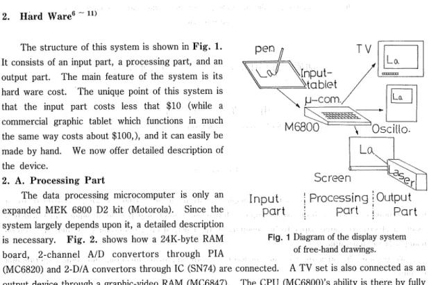
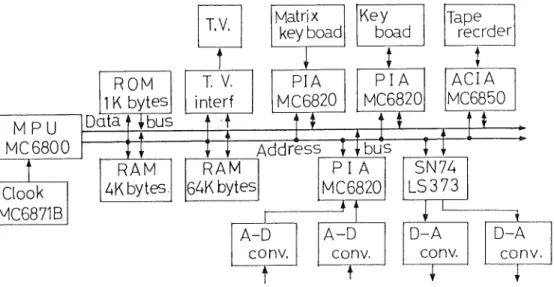
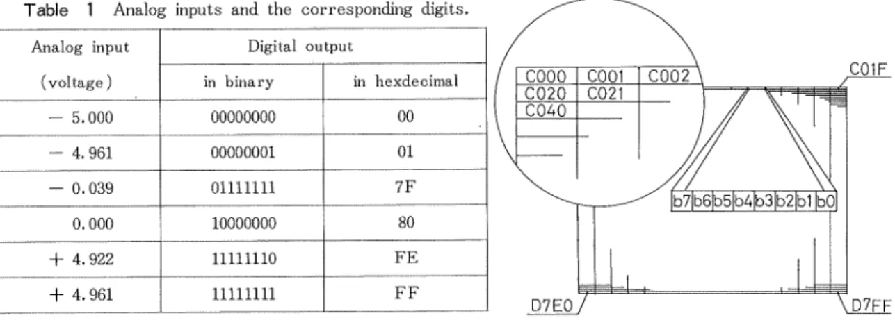
(3) 52. Sekiji YAMAGATA. whose main mechanism is a carbon-paper with applied electric fields in horizontal and vertical directions. The input-tablet is cheap and convenient, so that it can be produced in quantity. Distribution of the tablets to the students will help them to express themselves, as well as help the teacher to examine the responses of the students. This presentation includes descriptions of the apparatus and its operation and the role played by the microcomputer.1 ~ 5> Experiments have proved the system to be effective, especially for a. television display which duplicates the original figure precisely.. 2. Hard Ware6 -11). The structure of this system is shown in Fig. 1.. TV. pen. It consists of an input part, a processing part, and an output part. The main feature of the system is its. Lo. I:. ^^. hard ware cost. The unique point of this system is. that the input part costs less that $10 (while a commercial graphic tablet which functions in much the same way costs about $100,), and it can easily be. made by hand. We now offer detailed description of the device.. Screen. 2. A. Processing Part The data processing microcomputer is only an. expanded MEK 6800 D2 kit (Motorola). Since the system largely depends upon it, a detailed description is necessary. Fig. 2. shows how a 24K-byte RAM board, 2-channel A/D convertors through PIA. Input | Processing i Output part ; part | part Fig. 1 Diagram of the display system of free-hand drawings.. (MC6820) and 2-D/A convertors through 1C (SN74) are connected. A TV set is also connected as an output device through a graphic-video RAM (MC6847). The CPU (MC6800)'s ability is there by fully utilized. Fig. 3. shows the memory map of the microcomputer. In the map, the 1-0 port and the graphic video-RAM have significance for the system. The 1-0 port's major functions are the A/D convertors. The D/A convertors and a control switching output send signals from the microcomputer. Analog signals taken in by the microcomputer must be converted to digital signals in order to be,processed. The reverse process is necessary for the output because the output laser apparatus is controlled by analog signals. When certain voltages (analog signals) are applied to an A/D convertor, it transforms them to 2-byte digits which are shown in the A/D convertor addresses. (8004 and 8005 of the memory map); when the 2-bytes digits are stored in the D/A converter addresses, the outputs cary corresponding voltages. Fig. 4. compares the input and output signals of the microcomputer. The waves at the top are the analog inputs of the A/D convertor and the dotted waves at the bottom are the output signal fropi the D/A convertor. As the oscilloscope display shows, they coincide very well. Table. 1. shows. (52).
(4) A Microcomputer-controlled Real-Time Display System of Free-Hand Drawing for Educational Uses 53. MPU MC 6800. ROM ]1K bytes]. Data f ^ bus. RAM. ^bytes. Clock. MC6871B. T.V.. Matrix key boad. T. V.. PIA. MC6820. interf. Tape reader. PIA MC6820. ACIA MC6850. t. I:. 1. T. Key boad. Address I [ bus TT SN74 PI A LS373 |6^»K bytes MC6820. 1. RAM. T. J:. A-D. A-D. conv.. T. conv.. T. D-A conv.. T. X. D-A. conv.. Fig. 2 Block diagram of expanded M6800 microcomputer system.. $FFFF ROM AREA $EOOO $DFFF. TVD-02. 27 26 25 24 23. Not Used. 22 21. ;raphic V-RAM. $cooo $BFFF $BOOO $AFFF $A200 SA1FF $AOOO ?9FFF $3000 ?8FFF $8000 ?7FFF. 8FFF FE PD FC. l/8k STACK AREA 4k STATICK RAM. 1-0 PORT. 32k x 2pages D RAM. 20 II 10 CF OE OD oc OB OA 09 08 07 06 05 04 03 02 01 $8000. Hexadecimal Key Boacd Hexadecimal L.E.D.. D~A Converter D-A converter ~O^K Convertor Switching Output D-RAI.I Page Switct^. A CIA A-D Convertor A-D Converter Not Used Matrix Key Board. $0000. Fig. 3 The memory map of this system.. Fig. 4 Experimental results when the system was used as a digital wave memory, (a) above lOOOHz sinewave input and below output signal of the system, and (b) above 2500Hz sinewave mput and below output signal of it.. (53).
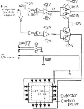
(5) 54. Sekiji YAMAGATA. the analog inputs (voltages) and the corresponding digits expressed in both binary and in hexdecimal systems. (Both systems are presented because both expressions are necessary to describe the microcomputers operations. Henceforth, the numbers without units or notions hexdecimal expressions. For other expressions, untis or notions will be added.) The switching output emits certain voltages or it does not, according to the contents of the switching output address. The addresses from COOO to DFFF are assigned to a graphic video-RAM, but the present usage requires addresses from COOO to D7FF. Fig. 5. shows how the addresses are assigned to the. CRT. The CRT screen is divided into 1800 (or 6144 in the decimal system) rectangles, each assigned to a certain address, which is again divided into 8 squares, each assigned to a certain secton of the address. If a given bit content is 0, the square is white. Table 1 Analog inputs and the corresponding digits. Analog input. Digital output. (voltage). in binary. - 5.000. 00000000. 00. - 4.961. 00000001. 01. - 0.039. 01111111. 7F. 0.000. 10000000. 80. + 4.922. 11111110. FE. + 4.961. 11111111. FF. C01F. in hexdecimal. D7EQ7 \D7FF Fig. 5 The adress assignments oif the CRT.. 2. B. Input Partl8) The input tablet and the switching-box compose the input part. Fig. 6. shows structure. The input tablet's frame is made of plates of synthetic resin and the construction of its' mechanism is shown in Fig. 7. A piece of carbon paper with a uniform electric resistance is an important device. The electrical biases are applied to this paper through 4 or 5 electrodes attached to each of the paper's edges. The electrodes at each edge makes a group, 2 groups' make a pair, connected by an electric and exchanges are caused by the switching signals from the switching-output controled by the microcomputer. A diode is connected to each electrode in such a way that only one direction is allowed for the electric currents between the groups facing each other, i. e. only a downward current between the upper and lower electrode-groups and a current from right to left between the left-and right-side groups. The two currents are perpendicular to each other from nearly strait equipotential lines perpendicular to them, as shown in Fig. 8. A sheet of special resin is placed between the carbon paper and the detecting electrode made from a copper plate. This resin sheet has a point electric current from outside to opposite surface when a point pressure is applied to that point. The detecting electrode is connected to an A/D convertor through an impedance transducer circuit. When the pen touches the input tablet's writing plane, the voltage of the point comes on and is applied to the A/D convertor.. (54).
(6) A Microcomputer-controlled Real-Time Display System of Free-Hand Drawing for Educational Uses. ~+5V. from 47Ki computer. (switch C. [saTgtnTl) "X LSOf—1<741' -12V. A/D conv. (]. T _.4»)-Detector .Carbon. paper. Fig. 6 Input tablet and bias circuit (swiching circuit or box) are shown.. -w^—/ Carbon Paper. ~/ Special Resin Sheet Detector. Plate (Cu). Coordinate Signal to A/D Converter. Swiching Circuit. Swiching Signal from Computer. Fig. 7 Construction of the input tablet.. (55). 55.
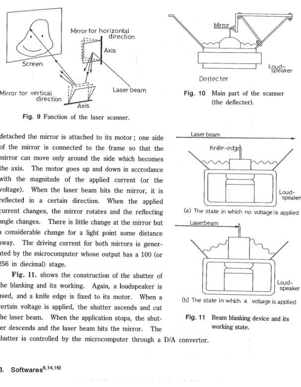
(7) 56. Sekiji YAMAGATA Individual difference of pen-pressure and pen-speed vary the. resistance between the carbon paper and the detecting electrode from a few Ohm to 2K Ohm. As the A/D convertor has a 5K Ohm input impedance, these electrical resistance fluctuations of the carbon paper-detecting electrode are not negligible. The impendence of the transducer circuit is to increase the output impedance of the input tablet, and thus render negligible the changes of the carbon paper-copper plate resistance. The voltage signal of the coordinate given by a pen-touch is stored in the memory of the microcomputer as a converted digital datum. Only after storage are contents of the switching. Fig. 8 Equal potential lines on the carbon paper.. output address changed, and this changes the direction of the equipotential line perpendicularly. The new voltage is agin applied to the A/D converter, and also stored in the memory, and these two piece of data represent the vertical and horizontal components of the pen's position. It takes less than 3 ms. to store data about a point pressure, a time short enough for human drawing speeds. Beside the said input tablet the switch-box contains a control cricuit and two switches connected to the microcomputer. One is the elmination switch and the other is the partial rejection switch. A closure of the elimination switch elminates the displayed figures and restores the initial states, so that a new drawing can be started. A closing of the partial rejection switch causes the pen to as an eraser as long as the switch is closed. 10'11) 2. C. Output part6-" Two methods are used for display: a display utilizing the TV and one utilizing the laser apparatus. Both of them are made of commonly-used devices, and the utilization of either or both of them is easily carried out by a few changes in the soft-ware. For the TV display, the CRT screen is. divided into 256 X 193 pixels (in decimals). The pixels signifying the positions touched by the pen are turned to black from the original white. The way the color of the pixels changes has already been described. ) The unique display process of this system is the one using a laser. The laser beam is deflected two-dimentionaly by the laser scanner according to the input signals. If a light turns on and off 24 times per second, the human eye cannot discern the blinking because of the after image effect. So if a light point caused by the laser beam traces a specified course 24 times per second, all the points along the course light up 24 times per sec., and the figure drawn by the course on the wall or on the screen will glow. The course of the light point is set by the laser scanner. Fig. 9. shows the function of the laser scanner. The laser scanner has two mirrors, both of which have their respective revolving axes perpendicular to the laser beam and to each other. One axis is horizontal and another vertical, so when the one mirror moves, the beam turns vertically and when other mirror moves, the beam turns horizontally. The combined effect of both mirrors enables the scanner to control the position of the. light point. Fig. 10. shows the main part of the scanner. The frame is loud-speaker whose cone is. (56).
(8) 57. A Microcomputer-controtled Real-Time Display System of Free-Hand Drawing for Educational Uses. Mirror for horizontal direction. -] ~ Lay d_-;.. "speaker. Deflecter Mirror for vertical direction. Laser beam. Fig. 10 Main part of the scanner (the deflecter).. Fig. 9 Function of the laser scanner. detached the mirror is attached to its motor ; one side of the mirror is connected to the frame so that the. Laser beam. Knife-edge|). mirror can move only around the side which becomes the axis. The motor goes up and down in accrodance. with the magnitude of the applied current (or the voltage). When the laser beam hits the mirror, it is. Loudspeaker. reflected in a certain direction. When the applied current changes, the mirror rotates and the reflecting angle changes. There is little change at the mirror but. (a) The state in which no voltage is applied Laserbeam. a considerable change for a light point some distance away. The driving current for both mirrors is generated by the microcomputer whose output has a 100 (or. 256 in diecimal) stage. Fig. 11. shows the construction of the shutter of. Loudspeaker. the blanking and its working. Again, a loudspeaker is used, and a knife edge is fixed to its motor. When a certain voltage is applied, the shutter ascends and cut the laser beam. When the application stops, the shut-. (b) The state inwhfch a voltage is applied Fig. 11 Beam blanking device and its. ter descends and the laser beam hits the mirror. The. working state.. shutter is controlled by the microcomputer through a D/A convertor.. 3. Softwares6'14'16'. The flow chart of the program for this system is shown in Fig. 12. The program contains a main program and 6 subprograms: the read subprogr'am, the computation subprogram, the TV display subprogram, the laser projection subprogram, the shuttering subprogram, and the partial rejection subprogram. It is easy to rearrange and to substitute subprograms according to user requirements. The subprograms are sorted into three categories for the convenience of the. (57).
(9) 58. Shigeru TAKEUCHI. Read Sub Pro9ram a point (X,Y) on input tablet Compute Program a coordinate(x,y) Store on memories Disply Sub Program a coocdinate(x,y) on TV. Laser Projection Sub Program. .of. In Need Branking. Yes Shuttering Sub Program. Nou-. Partial Reject Key. Yes. Partial Reject Sub Program. ON. No No. All JRS: Jump to Sub. Reject Key. ON. Routine Program Yes_. All Reject Program. Fig. 12 Flow chart of main program for input and output.. explanations. The categories are A) Data Reading/Computing part, B) Display Part, and C) Partial RejectionlElmination Part. The first part is acomplished by the read subprogram and the computation subprogram, the second either by the TV display subprogram or by the laser-projection. subprogram and the shuttering subprogram, while the third is effected by the partial rejection. (58).
(10) A Microcomputer-controlled Real-Time Display System of Free-Hand Drawing for Educational Uses 59. subprogram.. 3. A. Subprogram of Data Reading/Computing Part The function of this part is to read in the data of the pen's positions, to test them to examine whether they are appropriate or not, and to store the appropriate data in thhe memory area. The stored data are then accessible for the subprograms of the display part.. As we have described, in the explanation of the input tablet, the pens position on the writing plane is signified by the magnitude of the pair of voltages (which compose the data of the horizontal and the vertical components); these are converted into digital signals expressed in hexadecimal numbers. Collection of the coodinate data is controlled by the switching output signals. The coordinate data that are thus read in undergo 3 tests : a ground level test, an identity test, and a noise test. The computeation subprogram performs the test and the whole test take less than 0.33m sec. All data that fail one of these tests are rejected and will not be recorded on the displays. The ground leseltest is to exclude the ground level voltages (nearly 0 vlt.). The construction of the pen implies that when it is not in contact, the voltage read by the A/D convertor is the ground. level voltage, which also signifies the central part of the writing plane. So each time the pen is lifted, the microcomputer reads it as the pen's touching the center of the plane and stores it as data. When the drawing becomes complicated, and the pen is frequently lifted, it causes considerable waste of memory area.. To avoid this, any data with horizontal and vertical componets in the range 7C to 89 are excluded from further operations. Table 1 shows that ground level voltage is turned to the digital signal 80, so that small level voltages from 0.324 Volt. to -0.156 Volt. are ignored by the program. Thus no data reading occurs when the pen is lifted from the plane. But this also makes the area of 5 X 4 dots at the center of the CRT unuseable as draning space.. The identity test is to examine whether the read position of the pen is identical to the position read in one cycle before. If both the points are identical, further operations are unnessary. Without this test, when the pen halts for half a second, the position is read in 185 times and stored as 185 separate dots. The noise test is used to reject noises which are the unintentional signals caused by pickup of the circuits in the switch box, in the microcomputer, and for other electric reasons. If they cause dots on the display, they function as disturbances. So all data are again compared with the data one cycle before. The horizontal and the vertical distances between the pen's present positions and the positions one cycle before are calculated. If the differences between components exceeds 04 (in digit) or either of the distances exceeds 3.6m meter, the stordge in the memory area is postponed. As the drawing speeds rarely exceed 12m/s (3.6mm/0.3ms), data that signify a position out of the said range of former position can be considered as generated by noise. These data are reserved to be compared with the next data. Without the reservation, the data for the head of a newly started line will not be stored in the memory area. Only after these tests, the data is stored in the memory area. The addresses from 0000 to 5FFF are reserved for the memory area, to which the subprograms of the display part refer later. The memory area can store the information for 12287 dots (in decimals).. (59).
(11) 60. Sekiji YAMAGATA. 3. B. Subprogram of Display Part. The display part includes three subprogras : the TV display subprogram, the laser display subprogram, and the shuttering subprogram. The TV display is effected by the TV display subprogram, and the newly stored data are added to the graphic video RAM memories. Two other programs are utilized for the laser display.. (1) The CRT Display on the TV The way to initiate a display on the CRT has already been discussed. Fig. 5. shows the adresses' assignment. It is necessary to calculate the proper address and the right digit to be. stored. The first step is to divide the horizontal datum by 8 (the number of the bits included in an adress), using integer arithmetic. The result is added to D7EO (c. f. Fig. 5.) and the interger remainder is reserved. 3/4 of the vertical component is then calculated, because the vertical length. of the CRT is 3/4 of the horizontal length. The result is then multiplied by 20 and subtracted from the result of the former operation. The result is the address which includes the searched position. The integer remainder is stored in the address, and signified dot is displayed on the TV.. (2) The laser beam display As for as the TV display is concerned, the memory area in not necessary, because the coordinate data are directly stored in the graphic-video RAM to be displayed. The laser display needs continuous references to the memory area, however, since the laser beam has to repeated the pattern of a figure about 24 times per second. Experimentally, it has been found that the repetition can be reduced to 15 times per second for sufficent display. Since the reading and the processing of the data and the function of the shutter requires a certain time, it is occasionally impossible to read the whole memory area 24 times a second. When the figure becomes complicated and many memories are used, it is sometimes impossible to maintain the rate of 15 times per second. To increase the number of data being read in, 9 out of 10 pieces of data are omitted. The distances between the selected dots are calculated, and if some of the distances are too long and the. Movmentof mirror. vibration of the mirrors caused by the jumps is unavoidable, the shutter closing instructions are issued. The shutter's closures shield the laser beam, and they last for 4.0m see., the aproximate time for the cessation of vibration. Fig. 13 shows that while jumps and mirror vibration are taking place, the shutter remains closed. Data selection calculation of the distances, the data outputs and the shutter closing is carried out by the laser projection sobprogram. The work of the shuttering sobprogram is to open the shutter at the proper time.. •X... Delayed ^signal. ^. ^1. ^ CL a-1.. Cutoff\ ;;. region fM; oHaserr^ =F-h. a7mse5\L Brankingl signal. +. Delay time Time. U 3.4m sec,. I. Fig. 13 Concept of the beam blankmg (or shutter) function.. (60).
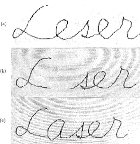
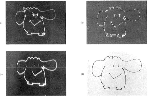
(12) 61. A Microcomputer-controlled Real-Time Display System of Free-Hand Drawing for Educational Uses. 3. C. The Partial Rejectio/Elmination Part6) The switch-box has 2 switches : the par-. (0). u". tial reject switch and the elmination switch. When the partial reject switch is closed, the partial reject subprogram is called. and reads in the position of the pen ; it defines. (b). a square of 16 X 16 dots around it and clears. the area by putting 0 to all the bits within the area. The decreases as the pen nears the edges of the writing plane. The erasing of a square take 1.9m see., Fig. 14 shows the. (°). correction of a display using the partial reject function.. The closed of the elimination switch. Fig. 14 Correction of a display using the partial reject. starts the program again from the intialization. function, (a) wrong writing, (b) Elimination. which clears the memory area and the graphic. caused by the partial reject function, and. Video-RAM addresses, and restores the initial. (c) corrected writing.. state for the display.. 4. Experimental Results and Evaluation. INPUT. Fig. 15. shows an original figure drawn on the. input tablet and its display on the CRT of the TV. The original figure was drawn by pencil on. ('). paper and as the picture shows, the TV display. H1J VWX.Y^. duplicates the original.18>. Fig. 16 (a) shows a figure drawn on a wall by the laser display, (b) is the same figure displayed by an osilloscope. Certain distortions and unnecessary lines are present, in (a). The distortions are due to the scanner s slow responses to the computer signals caused by the intertia of the mirror. The unnessaary lines are due to jumps of the lines on the input figure. The dog's body is. (b). drawn, the pen leaves the writing plane and jumps to one of the eyes. The light point follows the motion. It flashes from the body to the eye, yet a narrow line is left. This sudden motion causes another problem. It vibrates the mirror and blurs. (61). Fig. 15 Comparison between an original figure on the input tablet and the TV display..
(13) 62. Sekiji YAMAGATA. the head of the lines. We can see these problems when the picture (a) is compared with (b). The narrow lines and the blurs are removed by putting a blanking (or a shutter) system between the laser emitter and the mirrors. The shutter shields the laser beam while the mirror is either. flashing or vibrating, (c) in Fig. 16 is the same figure displayed by the laser with the shutter at work. The differences of the pictures (a) and (c) demonstrates the shutter's competence. When the blanking system is used the laser display does very well. If pictures (b) and (d) in Fig. 16 are compared, the omissions are clearly seen. The sensitive oscilloscope shows that the lines are divided into dots. The sampling is one tenth of coordinate. (b). •"vy-n,. w. Fig. 16 Figures on various display devices, (a) laser using display with no blanking, (b) oscilloscope. display, (c). laser display with blanking, and (d) TV display.. date. The dots are connected when they are given by laser display. The picture (d) in this Fig. is. displayed on the CRT of the TV. As the results of the display are good we conclude that a few improvements will make the system capable of practical use. As we mentioned in the introduction, one of the aims of the system is to provide every student in a class with an input tablet controlled collectively by the instructor. It is inefficient to construct microcomputers for each input tablet, so, for the processing part, the adaption of the Time Sharing System (TSS) is necessary. When the TSS is utilized, the microcomputer is able to control several input tablets. A test of four-input tablets TSS has already been carried out.15'171 And a color display of the TSS also has been made.. (62).
(14) A Microcomputer-controlled Real-Time Display System of Free-Hand Drawing for Educational Uses 63. 5. Conclusion Today, graphic tables with the same capability as ours are marketed, but they are designed for personal use and are too expensive for children to handle. This system is planned for educational purposes and its characteristics make it suitable for them. When the adoption of the TSS for the class room is conpleted, its superiority will be obvious. Other possible improvements under consideration are precise color graphics on the CRT, drawing data storage on floppy disks, and the taking of hard copies.12* A test of four-input tables TSS has already been successfully carried out. Reports on these tests will be presented in future articles. Further research will develop the system as a poweful educatioal device.. ACKNOWLEDGENTS The author stayed at the Department of Electronic & Electrical Engineering, University College, London from 1st October, 1983 to 31th July, 1984. The author wishes to thank Prof. E. A. Ash and staff of the department for many useful discussions with regard to the practical applications of this system.. This research started in 1978 as a graduation research program of the physics course to train students in the management of micro-processors. Training of this kind is essential for the teacher of the coming generations. Mr. T. Hashimoto (graduated March, 1982) constructed not only the main system but also the laser scanner ; Mr. H. Watanabe (graduated March, 1983) developed the function of partial rejection a simple input tablet, and the TSS of four-input-tablets ; Mr. H. Egashira (graduated March, 1984) estimated this system for educational uses ; Mr. T. Nomura (graduated March, 1985) developed soft ware for the color display on TV; and Mr, T. Wataki (graduated March,. 1986) developed both the input tablet for using ordinary paper, and the color disply TSS.. References. 1 ) S. Yamagata, T. Mizuno, T. Futou, T. Yamagami and K. Shimizu "TV Display Device for Handwritten Characters and Drawings for Educational Purpose By Means of Microcomputer." Res. Rep. of CAI, Hakodate College, Hokkaido Univ. of Educ., No. 8, pp. 133-181 (Mar. 1980). 2 ) S. Yamagata and K. Shimizu "Study on the Development of Educational Instruments Using Microcomputer, Rep. No. 1 A Display System for Handwritten Characters and Drawings." Res. Rep. Educ. Tech. Center, Hokkaido Univ. of Educ., No. 1, pp. 33-48 (Mar. 1980).. 3 ) S. Yamagata "Real-Time Display System of Free-Hand Drawing Used for Educational Purpose By Means of Microcomputer." The Lectures of 5th CAI Symposium at Sapporo, pp. 5-10. 9th Oct. 1980). 4 ) S. Yamagata "Display System of Free-Hand Drawing for Educational Use. "Trans, IECE, 63-D, 12, pp.. 1066-1071 (Dec. 1980). 5 ) S. Yamagata and T. Hashimoto "Some Improvements of Display Device for Characters and Drawing as Educational Purprse." Papers of Technical Guoup, IECE, JAPAN, ET-5, pp. 5-10 (Sept. 1981).. 6 ) S. Yamagata and H. Watanabe "A Display System for Handwritten Characters and Drawings with Partial Elimination Function." Hokkaido Section Joint Conv. Record of IECE, JAPAN, p. 248 (1982).. (63).
(15) 64 Sekiji YAMAGATA 7 ) S. Yamagata and S. Nakamura "Display Device for Handwritten Characters and Drawings by Means of Microcomputer." Res. Rep. of the Microcomputer Tech. Group, Hokkaido, 5, 8, pp. 2-11 (Aug. 1980). 8 ) S. Yamagata and T. Hashimoto "Expansion of MC 6800 Microprocessor— for Educational Puopose—." 4th Microcomputer Symposium, Sapporo, Res. Rep., pp. 26-33 (Aug. 1981). 9 ) S, Yamagata, T. Hashimoto and H. Watanabe "Study on Teaching Machines Using Microcomputer — Display Device for Handwritten Characters and Drawings—." Res. Rep. of Microcomputer Techn, Group,. Hokkaido, 7, 6, pp. 20-35 Qun. 1982). 10) S. Yamagata "Proposal for a Recording and Display System for Handwritten Characters and Drawing Using Microcomputer." Nat. Conv. Recod of IECE, Japan, S6-8, pp. 1-516-517 (1982),. 11) S. Yamagata and Hashimoto "Study on the Development of Educational Insturments Using Microcomputer, Repor No. 2 Betterment of Few Points Concerning the Display System of Free-Hand Drawing for Educational Use." Res. Rep. Educ. Tech. Center, Hokkaido University of Educ., No. 3, pp. 11-21 (Mar. 1982).. 12) S. Yamagata "Display System with Multi-Channel Free-Hand Drawing Input Tablets by Time Sharing System of Microcomputer." Tech. Rep. Telv. Soc., 6, No. 44, pp. 35-40 (Mar. 1983) 13) S. Yamagata and H. Watanabe "Study on the Development of Educational Instruments Using Microcompu-. ter, Report No. 3 Display System with Multi-Channel Free-Hand Drawing Input Tablets by TSS of Microcomputer." Res. Rep. Educ. Tech. Center, Hokkaido Univ. of Educ., No. 3, pp. 15-25 (Mar. 1983).. 14) S. Yamagata "Simplified Display System of Free-Hand Drawing Controlled by Microcomputer." Trans. IECE, Japan, J67-D, 1, pp. 9-16 Qan. 1984).. 15) S. Yamagata "Display System with 4-Channel Free-Hand Drawing Input Tablets by Time Sharing System of Microcomputer." Trans. IECE, Japan, J67-D, 2, pp. 177-183 (Feb. 1984).. 16) S. Yamagata "Simplified Display System of Free-Hand Drawing Controlled by Microcomputer." SYSTEM COMPUTER CONTROLS, 15, 1, pp. 57-64 (s/p Spirita Publi. Comp., 1984). 17) S. Yamagata "Display System with 4-Channel Free-Hand Drawing Input Tablets by Time Sharing Microcomputer System." SYSTEM COMPUTER CONTROLS, 15, 2, pp. 65-72 (s/p Spripta Publi. Comp., 1984). 18) S. Yamagata and T. Wataki "Simplified Free-Hand Input Tablet for Personal Computer." Hokkaido Section Joint conv. Record of IECE, Japan, p. 289 (Sept. 1985).. (64).
(16)
図
+6


関連したドキュメント
We extend a technique for lower-bounding the mixing time of card-shuffling Markov chains, and use it to bound the mixing time of the Rudvalis Markov chain, as well as two
It is suggested by our method that most of the quadratic algebras for all St¨ ackel equivalence classes of 3D second order quantum superintegrable systems on conformally flat
Nonlinear systems of the form 1.1 arise in many applications such as the discrete models of steady-state equations of reaction–diffusion equations see 1–6, the discrete analogue of
Keywords: continuous time random walk, Brownian motion, collision time, skew Young tableaux, tandem queue.. AMS 2000 Subject Classification: Primary:
Next, we prove bounds for the dimensions of p-adic MLV-spaces in Section 3, assuming results in Section 4, and make a conjecture about a special element in the motivic Galois group
The dynamic nature of our drawing algorithm relies on the fact that at any time, a free port on any vertex may safely be connected to a free port of any other vertex without
In order to be able to apply the Cartan–K¨ ahler theorem to prove existence of solutions in the real-analytic category, one needs a stronger result than Proposition 2.3; one needs
Here we shall supply proofs for the estimates of some relevant arithmetic functions that are well-known in the number field case but not necessarily so in our function field case..
