Title
Magnetostatic Wave Propagation over Different Bias Magnetic
Field
Author(s)
家形 諭
Citation
福岡工業大学総合研究機構研究所所報 第2巻 P19-P22
Issue Date
2020-2
URI
http://hdl.handle.net/11478/1504
Right
Type
Departmental Bulletin Paper
Textversion
Publisher
福岡工業大学 機関リポジトリ
FITREPO
Magnetostatic Wave Propagation over Different Bias Magnetic Field
Satoshi YAKATA (Department of Information Electronics, Faculty of Engineering)
Abstract
The propagation of magnetostatic wave in ferromagnetic material was investigated using micromagnetic simulation. In ferromagnetic medium, magnetostatic wave excited by rf magnetic field and the propagation over different internal magnetic field was observed. It is found that magnetostatic wave partially penetrated through the boundary between the regions which has different magnetic field. After penetration, the amplitude reduced significantly, and the wavelength increased depend on difference of magnetic field strength. The mechanism can be explained by dispersion relation of magnetostatic wave in ferromagnetic material. It is also exhibited application of exchange bias field by attaching anti-ferromagnetic material, Ir25Mn75 on Ni80Fe20 ferromagnetic
medium.
Keywords : magnetostatic wave, exchange bias, antiferromagnet
1. INTRODUCTION
The recent increase of mobile communication device makes explosive increase of data traffic. According to CISCO white paper annual report, it is predicted that the amount of annual data traffic will reach 4.8 Zetta byte by 2022 in whole world, which is 3 times larger than that of 2017. 1) Utilizing of above GHz band in range is
the only solution to support the data traffic increasing significantly. In fact, for the coming next generation network system, it has been mentioned to use above 6 GHz band to realize lower latency and larger data communication between mobile network devices. 2)
However, there are several technical barriers for achieving high frequency telecommunication devices because resonator have to be adapted for high frequency band.
Resonator is the key element for signal processing devices. For the resonator, piezoelectric material, such as quartz, has been used because it can realize high quality factor and temperature stability. On the process of signal resonator, received electric signals are converted to acoustic waves. The acoustic waves propagate on piezoelectric medium and confined between arrayed reflector to filter signals.
While increasing the signal frequency, wavelength and distance between arrayed reflector decreases. Therefore, to retain precision of signal processing for high frequency, it is necessary to suppress volume expansion of piezoelectric material thermal fluctuation. Although there are many studies to suppress thermal fluctuation of piezoelectric material, it would reach physical limit, with increasing signal frequency.
Magnetostatic wave in ferromagnetic material is one of the candidates to solve this thermal problem because the influence of volume expansion to magnetostatic wave could be further less than that of acoustic wave. Actually, the signal processing application
utilizing magnetostatic wave had been studied because magnetostatic wave can handle sub-THz signal and tunable by external magnetic field.3),4) Despite of its characteristic feature,
most of magnetostatic wave signal processing device has not been in practical yet because it could not show wave reflection mechanism which is necessary to realize resonator.
Previously we suggested anti-ferromagnetic material Ir25Mn75
as magnetostatic wave reflector since locally generated bias magnetic field can limit wave penetration from not biased region. we also have exhibited the MSSW propagation was clearly prohibited at the boundary between different biased magnetic field.5)
In this paper, we perform micromagnetic simulation again and explain the principle of wave reflection and behavior of penetrated wave over the boundary of different magnetic field. Though it was reported that the partial reflection of magnetostatic wave can be realized by fabricating physical step on ferromagnetic medium thickness, utilizing exchange bias magnetic field caused by anti-ferromagnet material could be more precise and realize perfect reflection of magnetostatic wave.
We also exhibit that the exchange bias field can be applied on Ni80Fe20 medium attached anti-ferromagnetic material Ir25Mn75 by
the measurement of ferromagnet resonance. 2. EXPERIMENT
2.1 MICROMAGNETIC SIMULATION Micromagnetic simulation was performed by solving Landau-Lifshitz micromagnetic formalism using mumax3 which was developed at Ghent University. 6) In our micromagnetic simulation,
the ferromagnetic medium consists of 10 nm cubic unit cell and forms 7.5 × 30 um rectangular with 10 nm in thickness (Fig. 1).
Satoshi YAKATA
The dimension was chosen to be convenient for actual micro fabrication. Saturation magnetization, exchange stiffness, and intrinsic damping constant were set as 800 emu/cc, 13×10-12 J/m
and 0.01, respectively to emulate typical permalloy (Ni80Fe20)
magnetic properties. Magnetic crystalline anisotropy was not set. External static magnetic field were applied along the short side of rectangular (Y direction in Fig. 1). Magnetostatic wave was excited by applying alternating magnetic field on each cell at X = 0 and ±1 along X direction. Alternating magnetic field is practically induced by rf current with antenna electrode placed on top of the ferromagnetic medium. The amplitude was 10 mT for visual clarity which is quite strong for alternating magnetic field, however it will not influence on characteristic of reflection and propagation for magnetostatic wave. The alternating frequency was fixed between 6 GHz. Nonreciprocity of magnetostatic wave will not be discussed here because the reciprocity is neglectable for Ni80Fe20 medium.
When anti-ferromagnetic material is attached on ferromagnetic material, unidirectional exchange bias magnetic field is induced in ferromagnetic material. To emulate this unidirectional exchange magnetic bias, additional static magnetic field was applied on the region where anti-ferromagnetic material has been attached along external magnetic field.
2.2 FERROMAGNET RESONANCE MEASUREMENT FOR Ni80Fe20/ Ir25Mn75 BILAYER
In this study, Ni80Fe20 (5 nm) and Ni80Fe20 (5 nm)/ Ir25Mn75(5
nm) films were prepared on glass substrate using high vacuum magnetron sputtering system. The base pressure was 5.0×10⁻⁴ Pa
and Ar pressure was 0.5 Pa. Ni80Fe20 and Ir25Mn75 were deposited
continuously without breaking vacuum at room temperature. On deposition, static magnetic field 0.4 T was applied in-plane to form magnetic anisotropy for Ni80Fe20 and induce unidirectional bias
field caused by Ir25Mn75. These samples were cut into 5 mm square
and ferromagnetic spectrum (FMR) were measured using electron spin resonance (ESR) measurement system. On FMR measurement, sample was set in microwave cavity for X-band (9.5 GHz) and static magnetic field was applied and swept from 65 to 165 mT along the formed magnetic easy axis for Ni80Fe20.
3. RESULTS AND DISCUSSION
Figure 2 is the results of our previous work which shows amplitude of magnetization in Z axis for propagated magnetostatic wave in ferromagnetic medium from antenna.6) Magnetostatic wave
was excited at antenna with 6 GHz in frequency under static magnetic field 0.01 T. Colored region in grey represents magnetic biased region with anti-ferromagnetic material. The amplitude of total magnetic field including exchange bias field was shown as Hex
in figure. For example, Hex = 0.05 T indicates sum of static magnetic
field, 0.01 T and exchange bias field, 0.04 T is applied on ferromagnetic material in grey region.
FIG. 1. Schematic illustration of the system setup for micromagnetic simulation.
FIG. 2. Magnetostatic wave propagation crossing different magnetic field. Excitation frequency was fixed to 6 GHz.
FIG. 3. Schematic illustration of the system setup for micromagnetic simulation.
It is well known that the magnetostatic wave has 3 modes, called magnetostatic surface wave (MSSW), magnetostatic forward volume wave (MSFVW) and magnetostatic backward volume wave (MSBVW). 3),7) These modes can be distinguished by relative
direction between static magnetic field and wave vector. In our simulation, since magnetostatic wave propagated perpendicular to external magnetic field and external magnetic field was applied in-plane, one can see magnetostatic surface wave (MSSW) mode is dominant. The wavelength of excited magnetostatic wave was 880 nm that is corresponding to calculated value from dispersion relation eq. (1) of MSSW mode. 7)
𝑀𝑀 is saturation magnetization, 𝛾𝛾 is the gyromagnetic ratio (= 1.84 × 10⁷ Hz/Oe) , 𝐻𝐻 is static magnetic field, 𝑑𝑑 is
thickness of sample, and 𝑘𝑘 is wave number of magnetostatic wave. One can see magnetostatic wave reduces its amplitude significantly after the penetration into this biased region due to reflection at the boundary between different internal magnetic field. The principle of wave reflection can be explained by the shift of dispersion relation.
Figure 3 shows dispersion relationship of MSSW mode for wavelength 0.88 μm and uniform mode (which is called FMR mode). The dispersion relation indicates which magnetostatic wave can exist in ferromagnetic medium. For example, to excite 6 GHz magnetostatic wave with wavelength of 0.88 μm, the magnetic field
H = 0.1 T must be applied. If the magnetic field is not 0.1 T, the
magnetostatic wave with wavelength of 0.88 μm would never be excited (another wave with different wavelength will be excited) It also indicates magnetostatic wave cannot propagate over different magnetic field even the ferromagnetic medium is physically continuous. However, figure 2 shows magnetostatic wave partially propagates over different magnetic field. This phenomenon can be explained as follows. The excited magnetostatic wave consist of various wavelength since applied alternating magnetic field for excitation is inhomogeneous. In this collection of 6 GHz wave, the wavelength 0.88 μm is dominant at H = 0.01 T. When these waves penetrate under biased magnetic field, where Hex is 0.01 T,
dispersion relation will shift and wavelength 1.23 μm will be dominant wave. In this condition, the magnetostatic wave with wavelength of 0.88 μm cannot penetrate into biased field that result in reflection of magnetostatic wave at the boundary of different biased field. Above a certain bias magnetic field, every magnetostatic wave reflected at the boundary which we can call perfect magnetostatic wave reflector. The critical magnetic field which forms perfect magnetostatic wave reflector can be estimated
from dispersion relation of ferromagnet resonance (FMR). The FMR is uniform precession mode of magnetostatic wave. One can say FMR is a kind of magnetostatic wave with infinity wavelength. This FMR dispersion relation is shown in fig. 3. The line indicates the border where magnetostatic wave can exist or not. For example, at magnetic field H = 0.06 T, no magnetostatic wave are allowed with 6 GHz in frequency. As shown in our previous work, utilizing this condition, one can create perfect magnetostatic wave reflector in physically continuous ferromagnetic medium. It has been reported that the strength of bias magnetic field can be modified by the thickness of Ir25Mn75. It also indicates the reflection rate can be
controlled with the thickness of Ir25Mn75. 8)
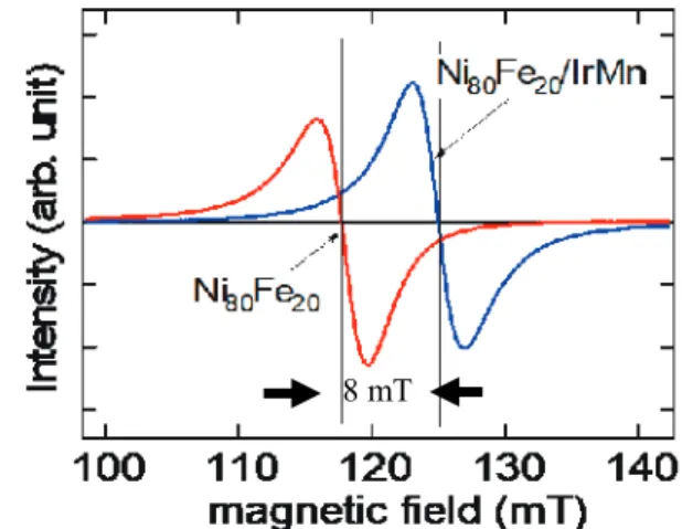
Figure 4 shows FMR spectrum for Ni80Fe20 and Ni80Fe20/
Ir25Mn75 bilayer. Since FMR measurement uses modulation method,
the spectrum shows differential of intensity which is proportional to energy dissipation by exciting magnetostatic wave in Ni80Fe20.
Therefore, the magnetic field at crossing 0 axis represent resonant magnetic field. The dispersion relation can be plotted directly from obtained resonant magnetic field and microwave frequency. In this case, 117 mT and 9.5 GHz for Ni80Fe20, respectively. This result is
corresponding to typical Ni80Fe20 FMR spectrum.
The resonant magnetic field was 125 mT for Ni80Fe20/ Ir25Mn75
bilayer. The value is significantly larger than that of Ni80Fe20. The
difference between resonant magnetic field is 8 mT which indicates the exchange bias magnetic field caused by Ir25Mn75 was applied on
Ni80Fe20.
The exchange bias is the result of facial interaction between Ni80Fe20 and Ir25Mn75. Therefore, the magnetic field strength would
decrease in Ni80Fe20 layer proportional to its depth. However,
magnetostatic wave in MSSW mode propagates on Ni80Fe20 surface
and Ni80Fe20 film is thin enough to neglect magnetic field difference
through the depth. It also can be seen from the FMR spectrum for Ni80Fe20/Ir25Mn75. If exchange bias field distributes through
8 mT
FIG. 4. FMR spectrum for Ni80Fe20 and Ni80Fe20/ Ir25Mn75. 𝑓𝑓𝑀𝑀𝑀𝑀𝑀𝑀𝑀𝑀=2𝜋𝜋𝛾𝛾 �𝐻𝐻 �𝐻𝐻 + 4𝜋𝜋𝑀𝑀 �1 +𝜋𝜋𝑀𝑀(1 − 𝑒𝑒
−2𝑘𝑘𝑘𝑘)
Satoshi YAKATA
Ni80Fe20 depth, it shows broadening of FMR spectrum as a result of
superposition of multiple spectrums. However, the linewidth of FMR spectrum for Ni80Fe20/Ir25Mn75 is mostly equivalent to that of
Ni80Fe20.
4. CONCLUSION
Magnetostatic wave propagation crossing over different magnetic field was observed by using micromagnetic simulation. When magnetostatic wave penetrate into the magnetic biased region, the wave amplitude was reduced, and wavelength increased. Theses phenomenon can be explained by the shift of dispersion relation caused by bias magnetic field.
Bias magnetic field can be applied by attachment of antiferromagnet material on ferromagnetic medium. In our FMR experiment for Ni80Fe20/Ir25Mn75, magnetic shift was observed due
to exchange bias.
5. ACKNOWLEDGMENT
This work was supported by the Electronics Research Laboratory from Fukuoka Institute of Technology.
(2019, 10,18 受付) References
1) Cisco Visual Networking Index: Forecast and Trends 2017–2022, 201
9.
2) 総務省:電波政策 2020 懇談会 報告書, 2020.
3) W. S. Ishak, “Magnetostatic Wave Technology: a Review.,” Proc. IEEE, vol. 76, no. 2, pp. 171–187, 1988.
4) 内海要三 and 堤誠, “静磁波(Msw)デバイスの動向,” テレビジョン
学会誌, vol. 38, no. 12, pp. 1053–1062, 1984.
5) mumax3 micromagnetic simulation, https://mumax.github.io/
6) S. Yakata, “magnetostatic wave propagation in magnetically biased
ferromagnetic film”, 福岡工業大学エレクトロニクス研究所所報, 第 33 巻, pp. 17-20, 2016.
7) Daniel D. Stancil · Anil Prabhakar. Spin Waves Theory and Applications. Springer, 2009.
8) M. Ali et al., “Antiferromagnetic layer thickness dependence of the IrMn/Co exchange-bias system,” Phys. Rev. B - Condens. Matter Mater. Phys., vol. 68, no. 21, pp. 1–7, 2003.