Transport properties of strongly correlated 2D electrons confined in microchannels
Author Jui‑Yin Lin
Degree Conferral Date
2018‑09‑30
Degree Doctor of Philosophy Degree Referral
Number
38005甲第21号 Copyright
Information
(C) 2018 The Author
URL http://doi.org/10.15102/1394.00000718
Okinawa Institute of Science and Technology Graduate University
Thesis submitted for the degree
Doctor of Philosophy
Transport properties of strongly correlated 2D electrons confined in
microchannels
by
Jui-Yin Lin
Supervisor: Denis Konstantinov
September, 2018
Declaration of Original and Sole Authorship
I, Jui-Yin Lin, declare that this thesis entitled Transport properties of strongly corre- lated 2D electrons confined in microchannels and the data presented in it are original and my own work.
I confirm that:
• No part of this work has previously been submitted for a degree at this or any other university.
• References to the work of others have been clearly acknowledged. Quotations from the work of others have been clearly indicated, and attributed to them.
• In cases where others have contributed to part of this work, such contribution has been clearly acknowledged and distinguished from my own work.
• None of this work has been previously published elsewhere, with the exception of the following:
Nonlinear transport of the inhomogeneous Wigner solid in a channel geometry, Physical review B 94, 195311 (2016) [1]
Sliding of an electron crystal of finite size on the surface of superfluid 4He confined in a microchannel, Physical review B 98, 085412 (2018) [2]
Date: September, 2018 Signature:
iii
Abstract
Transport properties of strongly correlated 2D electrons confined in microchannels
Wigner crystal is the solid phase of strongly correlated electrons. The main theme of this thesis work is employing a two-dimensional Wigner solid (WS) formed on the surface of liquid helium to probe interplay between, on the one hand, strong internal forces arising from electron-electron interaction and, on the other hand, external forces due to substrate and applied electrostatic potentials. To accomplish these studies we developed and employed a number of microchannel devices to confine WS system and measure its transport properties. First, we characterize the transport properties of a homogeneous electron crystal, an island of WS, and an inhomogeneous electron crystal in a microchannel geometry. We show how interplay between transport regimes of two individual electron crystals effect the overall I-V curves. A further study of WS system of varied size demonstrates how the energy dissipates from the edges of electron crystal through emission of ripplons, which thus affects the breaking of the strong coupling of WS with substrate excitations. Then, by introducing an external spatial periodic potential, we observed suppression of WS-ripplon coupling and re- entrant melting of WS when the amplitude of external potential is sufficiently high.
We interpret these phenomena as arising from the structural phase transitions in WS confined in a microchannel with spatially varied potential. This work is also relevant to the general study of the Frenkel-Kontorova model of interacting particles subject to a periodic substrate potential. Finally, some interesting features in the transport of strongly-correlated electrons have been studied in a T-shaped microchannel geometry.
In particular, experiments showed a breakdown of the conventional Drude bahaviour at sufficiently low temperatures and high electron densities, which could be due to effect of inertia of the surface excitations coupled to the WS.
v
Acknowledgment
Theses must acknowledge assistance received in the following areas:
• Designing the research: Denis Konstantinov, Alexander V. Smorodin, Alexander O. Badrutdinov, David Rees
• Sample fabrication: Laszlo Szikszai, Alexander V. Smorodin, Alexander O. Badrut- dinov, David Rees
• Executing the research: Alexander V. Smorodin, Alexander O. Badrutdinov, David Rees
• Analyzing the data: Alexander V. Smorodin, Alexander O. Badrutdinov, David Rees
• Interpreting the data/research: Denis Konstantinov, Alexander V. Smorodin, Alexander O. Badrutdinov, David Rees
vii
Abbreviations
2DEG two-dimensional electron gas BC scattering Bragg-Cherenkov scattering
BTE Boltzmann transport equation CVD chemical vapor deposition
DL dimple lattice
DSF dynamical structure factor EBL electron-beam lithography
EL electron liquid FEM finite element model FK model Frenkel-Kontorova model
GS Ground state
IDC inter-digital capacitor
KTHNY theory Kosterlitz-Thouless-Halperin-Nelson theory MOSFET metal-oxide-semiconductor field effect transistor
QTT quantum transport theory RIE reactive ion etching
SG equation sine-Gordon equation SSE surface-state electron
WS Wigner solid
ix
Nomenclature
c speed of light (2.997 924 58 × 10
8ms
−1)
~ Planck constant (1.054 572 66 × 10
−34Js) k
BBoltzmann constant (1.380 658 × 10
−23JK
−1)
ε
0permittivity of vacuum (8.854 × 10
−12C
2/(Jm))
Herelative permittivity of liquid helium (1.056 for
4He, 1.042 for
3He) e electrical charge of electron (1.602 × 10
−19C)
m
emass of electron (9.109 × 10
−31kg) α surface tension of liquid
4He
(3.76 × 10
−4kg/s
2at 0.6 K) (3.72 × 10
−4kg/s
2at 0.88 K) (3.69 × 10
−4kg/s
2at 1.1 K)
ρ volume density of liquid
4He (145.1 kg/m
3about 1 K)
xi
Contents
Declaration of Original and Sole Authorship iii
Abstract v
Acknowledgment vii
Abbreviations ix
Nomenclature xi
Contents xiii
List of Figures xv
List of Tables xvii
Introduction 1
1 Electrical transport in highly correlated electron systems 3
1.1 Bound states of electrons on liquid helium surface . . . . 5
1.2 Overview of transport theories . . . . 8
1.3 Scatterers: vapor atoms and ripplons . . . . 10
1.4 Electron-electron interaction . . . . 13
1.5 Nonlinear transport of electron crystal . . . . 16
1.6 Summary . . . . 20
2 Experimental methods 21 2.1 Device structure and manufacturing process . . . . 21
2.2 Experimental setup . . . . 24
2.3 Measurements and analysis . . . . 27
3 Inhomogeneous WS and multiple BC plateaus 33 3.1 Experiment . . . . 33
3.2 Results and Discussion . . . . 35
3.3 Summary . . . . 37
xiii
xiv Contents 4 Effect of finite size of WS on its nonlinear transport 41
4.1 Theoretical framework . . . . 41
4.2 Experiment . . . . 42
4.3 Results . . . . 44
4.4 Discussion . . . . 49
4.5 Summary . . . . 52
5 WS in microchannel subject to spatial periodic potential 53 5.1 Frenkel-Kontorova model . . . . 53
5.2 Experiment . . . . 55
5.3 Results . . . . 56
5.3.1 Phase diagram of electron system without applying periodic po- tential . . . . 56
5.3.2 Effect of periodic potential . . . . 57
5.4 Discussion . . . . 61
5.5 Summary . . . . 62
6 Electron flow in T-channel geometry 63 6.1 Experiment . . . . 63
6.2 Results . . . . 63
6.3 Discussion . . . . 67
6.4 Summary . . . . 68
Conclusion 69
Bibliography 71
List of Figures
1.1 µ
−14He(n
e) vs T . . . . 4
1.2 µ
−14Hevs T at n
e= 3.2 × 10
8cm
−2. . . . 5
1.3 SSE above bulk liquid helium . . . . 6
1.4 Probability density of bound SSE eigenstates . . . . 7
1.5 Fractional population of the ground state . . . . 8
1.6 µ
4He, µ
3Hevs T . . . . 11
1.7 τ (E
⊥) vs T . . . . 12
1.8 SE on an uneven interface . . . . 13
1.9 Topological defects in a hexagonal 2D lattice . . . . 15
1.10 Cherenkov radiation . . . . 17
1.11 BC scattering of WS . . . . 18
1.12 BC scattering: dimple lattice and nonlinear mobility . . . . 18
1.13 Force balance for an electron in dimple . . . . 19
2.1 FET vs. microchannel device . . . . 22
2.2 Microchannel device . . . . 23
2.3 Microchannel device in a copper cell . . . . 24
2.4 Liquid helium film in the channel . . . . 25
2.5 Parallel-plate capacitor model . . . . 26
2.6 n
eestimation . . . . 27
2.7 Lump circuit model . . . . 28
2.8 Locus for lump circuit . . . . 29
2.9 Time-resolved transport measurement for SSEs in BC scattering regime 31 2.10 Current I
outmeasured by a lock-in amplifier for WS in nonlinear trans- port regime . . . . 31
3.1 Inhomogeneous-WS microchannel device . . . . 34
3.2 I
outvs V
pp. . . . 36
3.3 dI
out/dV
invs V
inand V
G. . . . 38
4.1 Resistance oscillations under ac conditions . . . . 43
4.2 Finite-size effect microchannel device . . . . 44
4.3 Data sets S1D1-S1D3 measured in Sample 1 . . . . 45
4.4 Data sets S1D4-S1D6 measured in Sample 1 . . . . 46
4.5 Data sets S2D1-S2D3 measured in Sample 2 . . . . 47
4.6 Data sets S1D4, S1D5 measured in Sample 2 . . . . 48
xv
xvi List of Figures
4.7 E
s(max)vs L
WS. . . . 50
5.1 FK model . . . . 53
5.2 Periodic potential device . . . . 55
5.3 I vs V
sg, V
ch. . . . 56
5.4 I vs V
in, ∆V
F. . . . 58
5.5 GS of odd/even number of particles in one period . . . . 59
5.6 I vs V
sg, ∆V
F. . . . 60
6.1 T-shaped microchannel device . . . . 64
6.2 Flow of SSEs in T-channel at T = 0.4 K . . . . 65
6.3 Temperature dependence of current difference I
R− I
T. . . . 66
List of Tables
1.1 KTHNY predictions for a 2D isotropic system. . . . 14
xvii
Introduction
Understanding transport properties of strongly correlated electron systems is one of the important fundamental problems of modern condensed-matter physics. Supercon- ductivity is one famous example of a non-trivial transport property arising from the electron-electron interaction. The transport of electrons in such systems is a compli- cated affair that involves different processes, such as stochastic scattering processes with background scatterers, interaction of electrons with each other and with an ex- ternal driving field, etc. In general, all this processes are interconnected with each other.
The classical equation for transport of particles that involves the stochastic scat- tering processes in a dilute gas system is the Boltzmann transport equation (BTE):
df dt =
∂f
∂t
collision
, (1)
where f = f (~ r, ~ p, t) is the distribution function of particle in the phase space. It essentially describes the balance of forces due to, on the one hand, an external drive and, on the other hand, collisions with background scatterer. In a quantum mechanical treatment, the description of scattering is more intricate and involves quantum corre- lation functions, but the mechanism of force balance is universal. An average physical quantity of interest is described by the trace of a corresponding quantum mechanical operator over the statistical operator ρ, the density matrix operator, that must satisfy ˆ the quantum Liouville equation:
i ~
∂ ρ ˆ
∂t = − h ˆ ρ, H ˆ
i
, (2)
where H ˆ is the Hamiltonian of the system studied. Similarly to the classical kinetic theory, the quantum transport theory (QTT) derives system’s transport properties from the quantum Liouville equation using various approximations, such as the linear response approximation, etc. The main task in both classical and quantum transport theories is to deal with the scattering term, and the situation becomes significantly more complicated when the interactions between particles comprising the system can not be ignored. Unlike in the dilute weakly interacting systems which can be well described theoretically by the properties of the individual particles, qualitatively new behavior of a strongly correlated system, such as the superconductivity mentioned earlier, usually can not be predicted from a single-particle description. Strong inter-particle interaction results in a collective behavior, therefore new global and macroscopic properties may
1
2 Introduction appear. As often happened in the history of science, experimental observations of such new properties happen earlier than their theoretical development.
On the theoretical side, quantum Monte Carlo methods and density functional theory provide certain understanding of strongly correlated system. Nevertheless, such studies are significantly impeded by complexity of the problem and insufficiency of computation resources. As an alternative pathway, some theoretical models can be studied experimentally using a well controlled physical system [? ]. For example, some unsolved standard theoretical models of strongly interacting systems, such as the Hubbard and Frenkel-Kontorova models, has been recently studied using ultracold atoms and ions [3? ? –5]. Such experiments allowed not only to probe correlation effects between atoms and ions but also study effects of their interaction with external (substrate) potentials which can have great implications, for example, for the general study of friction [6].
Surface State Electrons (SSEs) floating above a free surface of liquid helium is a very promising candidate system for such studies. Unlike in other two-dimensional electron systems, the nature of background scatters is very well understood and theoretically described [7, 8]. Owing to a weak interaction with polar liquid, SSEs essentially reside in vacuum at a relatively large distance of 10 nm above the liquid and interact with each other by the unscreened Coulomb repulsion. In general, the potential energy of electron-electron interaction is much larger than electron kinetic energy and the system crystallizes into the solid phase already at temperatures about 1 K. Unique nature of the substrate, a quantum liquid which does not solidify down to the temperature of absolute zero, allows to study regime of strong coupling of SSEs to surface deformations.
This brings additional intriguing properties to the strongly-corrected system of SSEs on liquid helium.
This thesis is mainly about the experimental study of the transport properties of strongly-correlated SSE system, especially focusing on its solid phase. Experimentally, we study SSEs in microchannel devices which are built using microfabrication meth- ods, and measure electrical transport of SSEs subject to various device geometries and configurations of applied electrostatic potentials depending on the particular topic of research. In Chapter 1, we will briefly describe general properties of SSEs and out- line main theoretical frameworks used to describe electrical transport in this system.
The microfabricated devices and experimental methods will be briefly described in
Chapter 2. Different experiments with SSEs in such devices will be described in the
following four chapters (Chapters 3-6). This thesis will end with our prospective for
future studies.
Chapter 1
Electrical transport in highly correlated electron systems
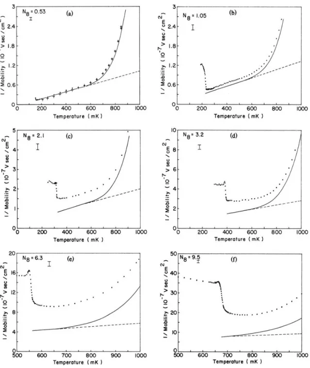
After the theoretical proposals of SSE system on liquid helium were introduced in 1969 [9, 10], many experiments with this system have been reported. It can be expected that SSE could serve as an ideal system for testing approaches in QTT because the properties of SSE scatterers are well known. It was found that for a dilute SSE system, the predictions of QTT are comparable with the experimental results. However, when approaching the strongly correlated regime at high electron densities, discrepancies between theoretical predictions and experimental observations become prominent. For example, in 1984 R. Metrota et al. have reported a systematic measurements of SSE mobility at different temperatures for various SSE densities n
e[11]. As shown in Fig. 1.1, for the liquid phase of SSEs the deviation of single-electron theory from experimental data increases with increasing n
e. For example, at n
e= 0.53 × 10
8cm
−2the experimental data are well described by the theoretical curve, see Fig. 1.1 (a).
However, at n
e= 3.2 × 10
8cm
−2the discrepancy between experimental data and theoretical curve is significant, see Fig. 1.1 (d).
Clearly, the single-electron approximation fails under the condition of high n
eand low temperatures. Unfortunately, the up-to-date theoretical models which attempt to include the inter-electron interaction are still unable to account for the discrepancy.
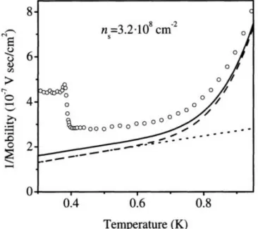
Inclusion of electron-electron interaction into the transport theory has been discussed by Monarkha and Kono in Chapter 3.3 of the book Two-dimensional Coulomb liquids and solids [7]. Predictions of many-electron theory are shown in Fig. 1.2. The theo- retical prediction (solid curve) for highly correlated electrons can only partly explain the observed increase in the resistance of SSE. The discrepancy between theory and experiment is still an open question.
At lower temperatures a sudden jump in the resistance seen in Figs. 1.1 and 1.2 indicates that the SSEs crystalize into a solid phase, i.e. the Wigner solid (WS). The transport of WS is nonlinear and rather complicated due to resonant coupling between WS and capillary waves on helium surface. This mechanism of resonant coupling be- tween WS and ripplon is related to coherent emission of ripplons by moving electron lattice; the corresponding transport regime is called the Bragg-Cherenkov (BC) scat- tering [? ]. This regime is rich of interesting physical phenomena discussed later in this thesis.
3
4 Electrical transport in highly correlated electron systems
Figure 1.1: Inverse mobility vs temperature for various densities. The elec-
tron densities denoted by N
8is in units of 10
8cm
−2. The solid dots and cross symbols
are the experimental data. The curves are the theoretical predictions of the single-
electron approximation (dashed: consider ripplon scattering only; solid: ripplon and
helium gas atoms). Figures are reproduced from [11].
1.1 Bound states of electrons on liquid helium surface 5
Figure 1.2: Inverse mobility vs temperature for SSEs with electron density n
e= 3.2 × 10
8cm
−2. The experimental data (open circle) are taken from Fig. 1.1 (d). The dashed curve is the theoretical result of the single-electron approximation for ripplon and helium gas atom scattering, the dotted curve is for ripplon scattering only. The solid curve is the prediction of many-electron theory. Figure is reproduced from [7].
This chapter will start with the description of the structure of quantized states of SSE. Then, the general theoretical frameworks used to describe electrical trans- port in strongly-correlated electron systems will be briefly reviewed in Sect. 1.2. The single-electron interaction with two kinds of background scatterers in our system, the vapor atoms and ripplons, will be discussed in Sect. 1.3. The consequences of the strong electron-electron interaction in SSEs are discussed in Sect. 1.4. The final sec- tion Sect. 1.5 will be focused on the Bragg-Cherenkov scattering, which is the main theme of the experimental studies described in this thesis.
1.1 Bound states of electrons on liquid helium surface
SSEs residing above the surface of liquid helium form a stable physical system. To
illustrate the basic structure of SSEs, we consider the following simplified model of a
particle of charge −e (e > 0) in vacuum (relative permittivity = 1) at a distance z
away from the plane interface of liquid helium (with relative permittivity
He). Helium
is an inert atom that heads the noble gas group in the periodic table. Its 1s orbitals are
fully occupied. Owing to the Pauli exclusion principle, an additional electron in the
vicinity of He atom must have its wavefunction to be orthogonal to occupied atomic
states, which leads to the strong repulsion between electron and He atoms. Therefore, a
strong repulsive force will prohibit electrons from entering liquid helium. The resulting
potential barrier at the liquid helium surface V
0is about 1 eV [12, 13]. In addition
6 Electrical transport in highly correlated electron systems
Figure 1.3: Simplified classical model for a single electron along liquid he- lium. A particle of charge −e representing electron floats above the free surface of liquid helium at a distance z. The image charge +eΛ locates below the electron at the same distance z inside the liquid helium.
to a strong short-range repulsion, there is a long-range attraction between electrons and bulk liquid. Whenever an electrical charge locates near a dielectric, instantaneous dipole moments of the polar atoms comprising the dielectric medium are induced. The electric field produced by induced dipoles exerts an attractive force on the electron.
The repulsive barrier and attractive potential are entirely responsible for the bound surface states of electrons above liquid helium.
For a flat unconfined liquid helium surface, the method of electrical images is used to yield an effective image charge q
0= +e
((He−1)He+1)
located inside the liquid at the same distance z from the liquid surface. Thus, the potential energy of electron at distance z can be approximated as
U
e(z) = V
0θ (−z) − k
eΛ
z + z
0e
2θ (z) + eE
⊥z, (1.1) where Λ =
4((He−1)He+1)
is a dimensionless constant much less than 1, θ (z) is the unit step (Heaviside) function, and E
⊥is the magnitude of an external electrical field applied normal to the surface. The parameter z
0' 1 Å is introduced in order to avoid the singularity of the image potential at the liquid helium surface [14]. Because V
0is much larger than the typical eigen-energies of electron in the potential Eq. (1.1), the simplified model with V
0→ ∞ and z
0→ 0 is usually used. When E
⊥= 0, the corresponding 1D Schrödinger equation is identical to that of the radial motion of electron in the hydrogen atom. The quantized energy levels along z axis for SSEs thus can be written as
ε
(⊥)n= − Λ
2R
en
2u − 0.65
n
2meV u − 7.5
n
2K, n = 1, 2, 3... , (1.2)
1.1 Bound states of electrons on liquid helium surface 7
Figure 1.4: Probability density of SSE eigenstates. Schematic diagram of the potential energy of interaction and the first three eigenstates of a single SSE above liquid helium surface.
where R
eis the effective Rydberg constant for SSE. The corresponding wave-functions are
Ψ
n(z) = R
10(z), n = 1, 2, 3... , (1.3) where R
10(r) is the well-known expression for the radial wavefunction of electron in the hydrogen atom. The probability density of the first three eigenstates and the image potential are plotted in Fig. 1.4.
Eq. (1.2) is obtained under the condition E
⊥= 0. In most cases of the experiments with SSE system, an external electric field E
⊥is applied normal to the liquid helium surface. For weak E
⊥the correction to eigen-energy can be considered in the first order perturbation theory, which results in the linear Stark shift:
δε
(⊥)n' eE
⊥hn |z| ni . (1.4)
For sufficiently strong E
⊥, that is such that the image potential can be disregarded, Eq. (1.1) results in a triangular-shaped potential well. Therefore,
ε
(⊥)n= eE
⊥ζ
lγ
F, (1.5)
where γ
F=
2meeE⊥~2
1/3and ζ
lis the l-th zero of the Airy function, Ai (−ζ
l) = 0 [15].
The corresponding wave-functions are
Ψ
n(z) = constant × Ai
"
z − ε
(⊥)neE
⊥! γ
F#
. (1.6)
8 Electrical transport in highly correlated electron systems
Figure 1.5: Fractional population of the ground state. Fractional population of the ground state plotted against temperature for different relations between holding electric field E
⊥and electron density. The dotted curve is the ratio of Q
b/Q
c, where Q
band Q
care the partition functions of the bound states Q
b= P
∞l=1
e
−ε(⊥)l /Tand the continuous spectrum states (determined by the container length L
z) Q
c=
q
meT8π~2
L
z, re- spectively. The ground state population is calculated according to
nn1=
exp(−ε(⊥) 1 /T) P
lexp(−ε(⊥)l /T)
, where n is the electron density. The dashed curve is evaluated for E
⊥= 9 V/cm.
Figure is reproduced from [7].
In the presence of E
⊥, the binding energy of a ground state electron and the energy difference between different eigenstates substantially increases. Accordingly, the frac- tional population of the ground state increases with E
⊥. As shown in Fig. 1.5, the fractional population of the ground state is almost 100% even for rather small pressing fields E
⊥. Correspondingly, for typical temperatures and pressing fields used in the experiments, SSEs are mostly in the ground state. Therefore, we can safely ignore occupancy of the higher eigenstate and focus on the transport of electrons confined in a 2D plane.
1.2 Overview of transport theories
In transport experiments we are interested with an effect of driving force on the motion
of the whole electron system. In a semiclassical theory, the relation between the electron
drift velocity v
dand the external driving field E ~
exis obtained from the BTE using
the relaxation time approximation. As outlined in the Introduction, BTE accounts
for stochastic scattering processes occurring in the system due to interaction with
background scatterers. Although the stochastic scattering events are random, a moving
1.2 Overview of transport theories 9 electron will receive more impacts from the collisions in the direction opposite to its motion. The number of such impacts is proportional to the velocity of the moving electron. The impacts due to background scatterers, therefore, give rise to the frictional force on an electron subjected to a driving force. The frictional force and the random background collisions must be related. The internal relationship of these microscopic forces is manifested in the so-called fluctuation-dissipation theorem. Without external driving force, the equation of motion including the thermal noise is
m v ˙ = −mγv + η, (1.7)
where γ is a coefficient appearing in the frictional force in the units of T
−1and η is the fluctuating force (noise) due to collisions with background scatterers. The solution to Eq. (1.7) is
v(t) = v
0e
−γt+ 1 m
Z
t0
dt
0η(t
0)e
−γ(t−t0), (1.8) where v
0= v(0). The physical meaning of the introduced coefficient γ is clear. It represents the inverse of the time scale during which an electron relaxes to attain equi- librium with the background thermal bath (the relaxation time approximation). For a large thermal bath we typically assume that the background noise η is white, that is the corresponding correlation function can be represented as hη(t
0)η(t
00)i = Γδ (t
0− t
00), where Γ is a measure of strength of thermal fluctuations. Then, by equating, on the one hand, the statistical average hv
2i obtained using Eq. (1.8) and, on the other hand, its thermal equilibrium average, a useful relationship between fluctuating and thermal equilibrium quantities can be obtained. For example, for a classical system we obtain the relation Γ = 2mγk
BT . In other words, the frictional dissipation rate γ, that is the inverse of the relaxation time, is related to measure of the strength of fluctuations in the background scatterers Γ. This relation represents the famous fluctuation-dissipation theorem.
Now let’s consider a system under an applied external electric field. The full deriva- tive in the BTE, see Eq. (1) in the Introduction, can be expressed as
df dt = ∂f
∂t + ~ p
m · 5 ~
rf + F ~
ex· 5 ~
pf. (1.9) Assuming that the system has an uniform density ( 5 ~
rf = 0) and has attained an equilibrium (
∂f∂t= 0), we have
df
dt = F ~
ex· 5 ~
pf = e ~ E
ex· 5 ~
pf, (1.10) where F ~
ex= e ~ E
ex. Under the relaxation time approximation, RHS of BTE can be expressed as
∂f
∂t
c
= f
eqγ − f γ = − f − f
eqτ , (1.11)
10 Electrical transport in highly correlated electron systems where γ = 1/τ , f
eqγ and f γ represent the rates of scattering in and out of the given volume of the phase space, respectively. Therefore,
f = f
eq− eτ ~ E
ex· 5 ~
pf = f
eq− eτ X
b
E
b∂f
∂p
b. (1.12)
The electric current density is J
a= e V
Z d
3~ r
Z d
3~ p
(2π ~ )
3f v
a≡
3
X
b=1
σ
abE
b, (1.13)
where σ
abis the conductivity tensor. For a quantum Fermi gas, f
eq=
1e(ε−εF)/kB T+1
, σ
ab= δ
abneM2τ= σ
aa. Eq. (1.13) represents the Ohm’s law, where σ
abis the Drude con- ductivity
i. The condition of force balance between the driving field and the stochastic scattering events automatically results in a terminal (drift) velocity, v
d, of the electron system.
The general framework to describe the single SSE transport is similar to the clas- sical Drude-Lorentz model [7, 16–18] outlined above. In a quantum treatment, the electron conductivity can be derived using the memory function expressed in terms of the electron density-density correlation function and its time and space Fourier trans- form, the equilibrium dynamical structure factor (DSF) [7? ]. The conductivity of SSEs can be written using the effective collision rate γ
eff, which is determined by the ripplon scattering at low temperatures and vapor-atom scattering at high temperatures and in general depends on the electron density n
e, in the form of σ = e
2n
e/m
eγ
eff. When n
eis sufficiently large, many-body effects become important, in particular the multiple scattering events involving at least two background scatterers. The relaxation time ap- proximation may be no longer applicable. When the scattering time becomes shorter than the momentum relaxation time, the initial state of the system at each collision event do not correspond to the equilibrium state of the background. The retardation effects become important, and spectrum of fluctuating force exerted on electrons devi- ate from the white noise. This results in the correlations between particle motion and complicates the mathematical description of the scattering processes. For strongly cor- related electron systems, the electron-electron interaction makes the equilibrium DSF hard to describe [19, 20]. For SSEs, in some cases it is still possible to incorporate effects of strong electron-electron interaction into the expression for equilibrium DSF using concept of the fluctuating many-electron field [7]. Nevertheless, in many cases the theoretical predictions of the many-body QTT are unable to explain experimental observations in SSEs, c.f. our earlier discussion and Fig. 1.2. Up to now, a complete theoretical tool for describing the electrical transport of electrons on helium is still missing.
1.3 Scatterers: vapor atoms and ripplons
There are two kinds of background scatterer in the system of SSEs floating above the free surface of liquid helium. One is the vapor atoms of helium, and the other is the
i
The Hall conductivity σ
abalso can be derived from the conductivity tensor.
1.3 Scatterers: vapor atoms and ripplons 11 capillary waves of the liquid surface, or ripplons in its quantized form. The number of both kinds of background scatterers decreases with cooling. The scattering rate by vapor helium atoms has been found to be independent of the SSE energy of the motion parallel to the liquid surfaces, and depends linearly on the density of vapor helium atoms n
(a)[7, 18, 21]
n
(a)(T ) =
M
aT 2π ~
3/2exp
− Q T
, (1.14)
where Q is the evaporation constant and M
ais the mass of the helium atom. Therefore, while n
(a)increases exponentially as the temperature rises, the electron mobility µ decreases exponentially with temperature
µ = 8ea
03π ~ An
(a)∝ T
−3/2exp Q
T
, (1.15)
where a
0is the effective Bohr radius of SSE and A is the scattering cross section of a He atom [18].
Figure 1.6: Comparison of µ
4Heand µ
3Heas a function of temperature.
Temperature dependence of µ
3Heis qualitatively same as the µ
4Hedata. The vapor- atom regime is shifted to lower temperatures for the
3He surface than that for the
4He case due to the higher vapor pressure of
3He. In the case of
4He, the gradual increase of µ
4Hebelow 700 mK is due to the crossover from atom- to ripplon-dominated scattering regime. Figure is reproduced from [22].
At low temperatures T < 0.7 K, the vapor density is extremely low. Therefore,
the SSE scattering is dominated by ripplons. The number of ripplons is described
by the Bose distribution function, and only the low energy ones are involved in the
momentum relaxation of SSEs, q ≤ 2k, where q is the wave number of ripplons and
k is the wave number of SSEs corresponding to their thermal motion along the liquid
12 Electrical transport in highly correlated electron systems surface. For ripplons with such q their energy ~ ω
qk
BT , which is the consequence of the ripplon dispersion relations ω
q= p
α/ρq
3/2. The corresponding density of such ripplons, therefore, decreases linearly with decreasing temperature [7, 14]:
n
(r)q(T ) = 1 e
~ωq kBT
− 1
' k
BT
~ ω
q. (1.16)
As a result, electron-ripplon scattering rate decreases linearly with T . For liquid
3He which has higher vapor pressure than
4He at the same T , the electron-vapor scattering extends to a lower temperature region, as shown in Fig. 1.6 [22]. At sufficiently low T , the mobility drops abruptly. This is caused by the Bragg-Cherenkov scattering when the SSEs are in solid phase. This will be discussed in the Sect. 1.5.
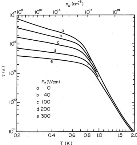
Figure 1.7: Momentum relaxation time τ as a function of temperature for various values of pressing field F
z. Below T ≈ 0.7 K, the ripplon scattering becomes dominant and shows significant F
zdependence. Note that Ohmic mobility µ = eτ /m
e. Figure is reproduced from [18].
The electron-ripplon interaction is described by the displacement function ξ(r) of
the liquid surface entering into the polarization interaction potential of an electron
with helium. It is strongly affected by the SSE probability distribution near the in-
terface. As discussed in Sect. 1.1 the SSE wavefunction Ψ
n(z) is strongly affected by
the pressing field E
⊥, therefore the electron-ripplon scattering is expected to depend
on E
⊥. Intuitively, at high E
⊥the coupling of electrons and ripplons increases, so SSE
1.4 Electron-electron interaction 13
Figure 1.8: A single SSE on an uneven surface. The diagram shows the wave function of an electron which do not follow the interface displacement (a) and for an electron that remains in the bound state (b). Figure is reproduced from [7].
mobility decreases [18, 23]. The momentum relaxation time of SSE for various values of pressing field E
⊥is shown in Fig. 1.7 [18]. The coupling term in electron-rippon interaction which is linearly proportional to E
⊥mainly results from the fact that an electron wave fuction in the bound surface state should be zero at the helium vapor- surface intreface, see Fig. 1.8 [7]. Therefore, when an electron encounters ripplons it should follow the surface displacement which results in the interaction potential energy U
int≈ eE
⊥ξ, where ξ is the surface displacement.
1.4 Electron-electron interaction
There is no intrinsic difference between scattering of an electron from another electron and that from other sources of scatterers, like vapor atoms and ripplons. Electron- electron collisions preserve total momentum of particles like other collisions do. But when describing the dynamics of the system of electrons under the influence of the en- vironment, electron-electron scattering within the electron system does not contribute to the momentum balance between the external forces applied to the electron system and the friction forces from their background scatterers. In other words, the exchange of momentum between electrons does not change the total momentum of the elec- tron system, therefore, it doesn’t affect the long-wavelength conductivity directly [?
]. The electron-electron interaction mainly affects the electron distribution function f
(in the classical kinetic equation treatment) or the density matrix ρ (in the quantum
treatment) [7, 24]. In the case when the corresponding momentum and energy redistri-
bution within the electron system is mainly governed by the inter-electron interaction,
the regime of electron transport is called the complete control regime. In another case
when only the energy redistribution is governed by the electron-electron collisions, it
is called the partial control regime. The redistribution of f (~ r, ~ p, t) is strongly related
to the relation between electron-electron collision rate ν
e-eand momentum/energy re-
laxation rate γ, and thus influences the transport properties significantly. The study
14 Electrical transport in highly correlated electron systems Table 1.1: KTHNY predictions for a 2D isotropic system.
Solid Hexatic Liquid
Dislocations bound in pairs free free
Disclinations bound in pairs free
Positional correlations quasi-long range short range short range
Elastic constant 6= 0 0 0
Bond-orientational correlations long range quasi-long range short range The difference between the three phases predicted by KTHNY theory. There are difference on two levels: (1) the presence of different types of topological defects, and (2) the type and range of correlations [8].
of strongly correlated electron systems is largely about the competition between indi- vidualistic and collective behavior of electrons.
Correlations between electron motion due to mutual interaction between parti- cles have large impact on statistical properties of SSEs. Owing to the property of self-organization, this is largely manifested in the emergence of some kind of ordered structures, such as the spatially ordered Wigner crystal [25]. Wigner crystal is the solid phase of the electrons in a structureless positive background. When the poten- tial energy of interaction between electrons U
eebecomes significantly larger than the kinetic energy K
e, the electrons eventually localize at the lattice sites in order to reduce their total energy. The ratio of the mean interaction energy to the mean ki- netic energy is called the plasma parameter, Γ ≡ hU
eei / hK
ei. For the system of SSEs floating above liquid helium, Γ = e
2√
πn
e/k
BT . The transition for SSEs into the solid phase is expected to occur at Γ = 130. The spatial structure of WS in SSEs on liquid helium is a 2D hexagonal lattice [8]. According to the KTHNY (Kosterlitz-Thouless- Halperin-Nelson) theory, melting of WS occurs in two stages through two continuous phase transitions: solid phase to hexatic phase, and hexatic phase to liquid phase. The phase transition is mediated via the unbinding of pairs of topological defects: disclina- tions and dislocations, as shown in Fig. 1.9. A disclination is an orientational defect that can be viewed as a particle having the wrong number of nearest neighbors, the so-called coordination number. A dislocation is a bound pair of disclinations of +1 and −1 coordination numbers. It maintains the long distance ordering with a much lower energy than an isolated disclination. The unbinding of dislocations will cause the system to loose its long-distance order and its resistance to shear stress. The response to shear stress is a key property to distinguish between solid and liquid phases. The melting of WS is generally mediated via the spontaneous unbinding of dislocations due to thermodynamic instability. In KTHNY theory, WS is elastic and characterized by the shear modulus G. The temperature dependence of the shear modulus can be ex- pressed as G(T ) = G − (1 − A · T /T
c), where T
cis the temperature of the first melting transition from the solid phase to the hexatic phase, and A is an constant which can be determined from the experiments [8].
There are two phonon modes of WS excitation spectrum. In long-wavelength limit,
the longitudinal phonon mode coincides with the 2D plasmon spectrum, while the
transverse mode follows the usual sound-like dispersion relation [7]. In WS, the phonon
1.4 Electron-electron interaction 15
Figure 1.9: Topological defects in a triangular lattice. (a) Isolated disclina-
tions. For a hexagonal lattice (coordination number is 6) there are disclinations with
coordination 5 and 7. They are indicated by (-) and (+) respectively and can be viewed
as topological charges. Note that a disclination is characterized by a mismatch in ori-
entation and the energy of such a defect is large. (b) Isolated dislocation. A dislocation
is a tightly bound pair of +1 and −1 disclinations. The ordering at long distance will
not be disrupted by a dislocation. And consequently such a bound pair has a much
lower energy. Figure is reproduced from [8].
16 Electrical transport in highly correlated electron systems modes and the motion of dislocations strongly interact with ripplons (one of the back- ground scatterers). The interaction of WS with a soft liquid substrate can result in a complicated dynamics associated with polaronic states when an electron becomes self-trapped into a surface dimple that it creates [26]. The coupled WS-dimple sys- tem can show striking behaviour, such as the nonlinear conductivity of WS in the Bragg-Cherenkov scattering regime and decoupling (sliding) transition [27? ].
1.5 Nonlinear transport of electron crystal
Cherenkov radiation (Nobel Prize in 1958) occurs when a charged particle moves in a medium at a speed faster than or equal to the phase velocity of the electromagnetic radiation it triggers in the medium [28, 29]. Although exact theory for this effect involves a full quantum mechanical treatment, main features of Cherenkov radiation are classical or semiclassical in origin. A moving charged particle polarizes the polar atoms of the medium. The coherent response of the medium as a whole is described by the distribution of electrical dipoles induced by the charged particle along its trajectory.
When the charged particle velocity v
pis faster than the local phase velocity of light in the medium, the induced dipole distribution is asymmetric and has a non-zero total dipole moment which radiates EM waves. Cherenkov radiation, accordingly, has a threshold velocity for the moving particle v
p(th)= c/ √
, where c is the speed of light in vacuum, and is the relative permittivity of medium. The propagation direction of the collective wavefront tangent to all circular wavefronts of the radiated EM waves is at an angle θ
cto the direction of the moving charged particle. This characteristics angle θ
ccan be interpreted qualitatively in terms of "shock waves" like the supersonic bomb or the bow shock from the moving object on liquid surface, see Fig. 1.10 [30].
The angle θ
cis approximately defined by the travel distance of the moving particle and the travel distance of the wave triggered at time t
0= t − ∆t,
θ
c≈ cos
−1v
wave× ∆t v
p× ∆t
, (1.17)
where v
waveis the phase velocity of the triggered wave. At v
p= v
wave, that is θ
c= 0, the Cherenkov radiation wavefront is moving in the same direction as particle.
For an array of moving particles, the Cherenkov waves emitted by different particles would interfere with each other. For the particles in an ordered structure, such as the Wigner crystal on the surface of liquid helium, the interference of the capillary waves generated by moving electrons is constructive when the wave vector ~ q of radiated ripplons equals the reciprocal lattice vectors G ~ of WS, see Fig. 1.11. This is similar to the Bragg scattering of X-rays or neutrons from a lattice. Enhancement in the amplitude of the radiated ripplons increases the collision rate of electrons with such ripplons, which results in strong increase of the momentum loss of WS. Therefore, the frictional drag force dramatically increases and results in the terminal velocity of WS:
v
BC= v
G= p
αG/ρ, (1.18)
where G is the magnitude of the reciprocal lattice vector. This is the model of the
Bragg-Cherenkov scattering which was introduced in 1997 by Dykman and Rubo [? ]
1.5 Nonlinear transport of electron crystal 17
Figure 1.10: Cherenkov radiation. Spherical wavelets of EM field radiated by a particle traveling with a speed less (on the left) and greater (on the right) than the speed of light in the medium. For υ > c/ √
, an electromagnetic "shock" wave appears moving in the direction given by the Cherenkov angle θ
c. Figure is reproduced from [30].
in order to explain the anomalous electrical conductivity observed in SSEs [27, 31]. In the BC scattering regime, the strong coupling between the WS and coherently emitted ripplons occurs. The constructive interference of surface waves form a commensurate dimple lattice (DL) underneath the electron lattice, such that the deepened surface deformation increases the friction force on electrons and slows down WS, see Fig. 1.12 (a). Under this condition, the effective electron mass increases and the WS mobility decreases dramatically. The drift velocity of the electron lattice is locked at v
BCso the electrical current of SSEs is I
BC= en
ev
BCw, where w is the width of WS. Therefore, in the BC scattering regime the differential conductivity of SEEs dI/dV ≈ 0, until decoupling occurs.
The decoupling of WS from dimples has been shown to be strongly related to the external driving force F
extapplied to the WS [27, 32, 33]. The two systems decouple when F
extis larger than some threshold value, F
ext(th). For example, as shown in Fig.
1.12 (b), the WS mobility abruptly jumps up when the driving voltage V
inexceeds 0.16 V for upward sweep and gets back to its value in the BC scattering regime when V
inis lower than 0.135 V for the downward sweep. The threshold voltages for both sweeps vary from run to run within about 10 %. A classical model aimed to explain origin of the threshold driving force F
ext(th)was proposed by Vinen who used a simple classical argument [34]. The terminal velocity of WS in the BC scattering regime results from the balance between the driving force F
extand the friction forces exerted on WS. Vinen considered this friction force F
DL(k)directed opposite to the WS motion as arising from the reaction force N ~ exerted on WS from the dimple lattice, see Fig. 1.13.
Correspondingly, he related the friction force F
DL(k)to the pressing force F
WS(⊥)≈ eE
⊥18 Electrical transport in highly correlated electron systems
(a) (a)
(a) (b)
Figure 1.11: BC scattering of moving WS. (a) Cherenkov radiation of a single moving particle when υ
p= υ
wave. The corresponding Cherenkov angle θ
cis zero. (b) Bragg-Cherenkov emission of surface waves by a moving WS on the surface of liquid helium.
(a)
(b)
Figure 1.12: Dimple lattice and WS nonlinear mobility. (a) Schematic view
of the surface deformation (dimple lattice) induced by the WS on liquid helium. (b)
Nonlinear conductivity of WS in the BC scattering regime and sliding transition. Figure
is reproduced from [27].
1.5 Nonlinear transport of electron crystal 19
Figure 1.13: Force balance for an electron in dimple. The reaction force N ~ on electron from liquid surface must balance the normal force F
WS(⊥)and an external driving force F
ext(not shown).
exerted on the electron perpendicular to the 2D plane by F
DL(k)= F
WS(⊥)∂ξ
∂x
x=xe
, (1.19)
where x
eis the position of the electron, and ξ is the vertical displacement of the liquid surface in the z direction. Note that the similar expression for the friction force F
k=
∂U∂xintcan be derived from the expression for the electron-ripplon coupling, U
int≈ eE
⊥ξ, which has been discussed in Sect. 1.3. Therefore, for a given value of the pressing electric field and a dimple profile ξ(x) there exists a maximum friction force F
DL,th(k)when the local slope attains maximum. Beyond this value the decoupling, or sliding, between WS and DL occurs, which leads to a sudden jump of WS conductivity as shown in Fig. 1.12 (b). However, this simple model does not account for bistable behaviour seen in this figure.
BC scattering occurs when the WS velocity approaches the resonance velocity of ripplons and results in the constructive interference of surface waves forming a commen- surate lattice of dimples. The physics is essentially described by the textbook problem of a forced harmonic oscillator, where surface vibrations represent the harmonic oscil- lator and the normal force exerted on the surface by WS represent the periodic driving of oscillator. The amplitude of the oscillator is essentially the depth of the dimple ξ.
For an oscillator without damping ξ will become infinity. It is, of course, unphysical.
To avoid this unphysical result, Vinen introduced a phenomenological damping coeffi-
cient v
dto account for the energy dissipation in the oscillator (the surface waves) and
found that ξ decreases with increasing v
d[34]. He suggested that damping arises from
two effects: the natural damping of the capillary waves and radiative loss of capillary
waves from an electron crystal of finite size. This hints that the sliding properties of
the WS can depend on its size. However, no experimental studies of such finite-size
effects where done in this system until now.
20 Electrical transport in highly correlated electron systems
1.6 Summary
In this chapter, we briefly reviewed the fundamental concepts of the transport theory
(Sect. 1.2),the electron-ripplon and electron-atom scattering (Sect. 1.3), the electron-
electron interaction and phase transition in SSEs (Sect. 1.4), and the non-linear trans-
port of WS (Sect. 1.5). In the following chapters we describes our experiments where
we aimed at achieving further understanding of some puzzling transport properties
in the strongly-correlated SSE system on liquid helium, in particular focusing on the
nonlinear transport of WS in the Bragg-Cherenkov scattering regime.
Chapter 2
Experimental methods
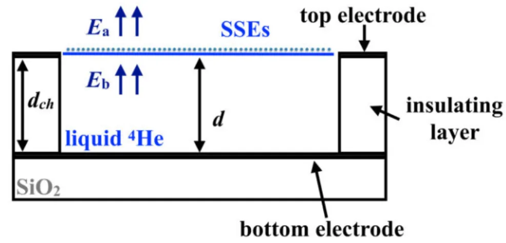
Recently, it was demonstrated that confining electrons in capillary-condensed mi- crochannel structures facilitates control of the electron system by imposed electrostatic potentials and allow to observe new interesting features associated with the electron transport and phase transitions in the system, such as a clocked electron transport [35], discrete transport through a point-contact constriction [36, 37], suppressed and re-entrant melting of a quasi-1D electron crystal [38–40], stick-slip motion of WS [33], inhomogeneous WS [1], etc. Motivated by these works, we designed and fabricated several microchannel devices for different research topics. We introduced varied config- urations of external potential imposed by microscopic electrode structures introduced along the microchannel. In most of our devices, there are two reservoirs located sym- metrically on the two ends of a long microchannel in order to provide source of constant SSE flow in the microchannel. One of our device, which will be described in details in Chapter 6, features three such reservoirs connected by a T-shape microchannel. The transport properties of SSEs subjected to the external electrostatic potentials of varied configurations are measured by the standard capacitive (Sommer-Tanner) method and further characterized by the analysis of a lump circuit model.
2.1 Device structure and manufacturing process
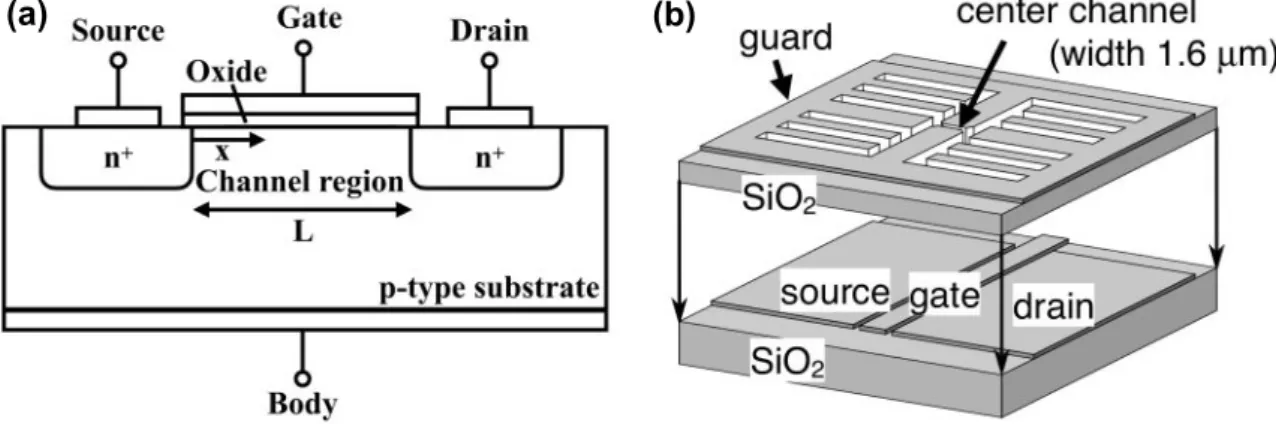
In general, the experimental device to study electrical transport in SSEs has the same structure as one for 2DEG in semiconductors. As shown in Fig. 2.1, the device to study electron transport consists of an active channel through which electrons flow from the source to drain. For the system of SSEs floating above liquid helium, we need a channel structure to maintain liquid helium in the source, drain and gate electrode ares. The channels are etched in the insulating material, therefore the depth of channels is defined by the thickness of the insulating layer. The guard electrode on the top of insulating layer is used to avoid charging of the top of the insulating layer. It also helps to confine electrons inside the channel. More negative voltage V
guconfines SSEs stronger such that the effective width of the charged system in a channel can be tuned by V
gu. Therefore, in order to have an independent control of the width of the electron system in the center microchannel an independent top electrode, the split-gate electrode, is usually introduced along the center microchannel.
21
22 Experimental methods
(a) (b)
Figure 2.1: Schematic view of the device for SSE experiments. (a) Cross sec- tion of a n-type Metal-Oxide-Semiconductor Field Effect Transistor (MOSFET). An electrical potential applied to the Gate electrode controls electron density in channel region. The current of electrons is measured between Source and Drain. (b) Schemat- ics of a microchannel device used for SSE transport measurements. The device has a double-layered structure with a top and bottom metal electrodes separated by an insulting layer. The center channel connects two reservoirs of SSEs. The SSEs are confined in the area above center channel by the negative-biased top guard electrode V
gu. The SSE surface density n
ein the center channel is controlled by the voltages applied on the bottom gate electrode and V
gu. Figure is reproduced from [41].
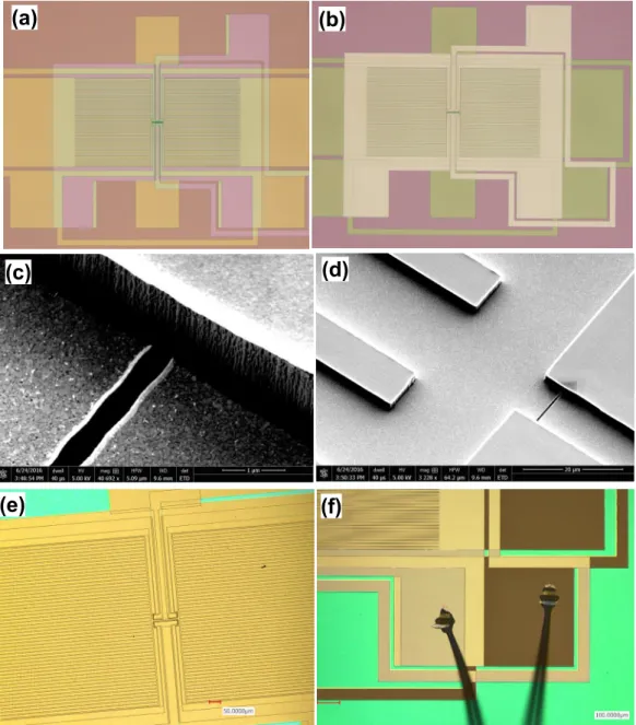
Exemplary images of one of the used devices are shown in Fig. 2.2. All the mi- crochannel devices used here are composed of two patterned gold layers separated by an insulating layer. The two layers of gold electrode can be distinguished by the colors in Fig. 2.2 (b). The bottom layer contains the reservoir electrodes, whose functions are similar to the Source and Drain in MOSFET, and the center microchannel electrode, whose functions are similar to the Gate in MOSFET. The top layer is composed of the guard and split-gate electrodes. Those two layers of microscopic structure are prepared by the lithography techniques. For the pattern of spatial resolution higher than 1 µm, the layer is prepared by the electron-beam lithography (EBL) technique. Otherwise, the micro structure is prepared by the UV lithography technique. The insulating layer varies for different microchannel devices from hard-baked photoresist to silicon nitride.
The insulating layer of hard-baked photoresist was made by OFPR or Shipley on hot
plate at 250
◦C for 30 minutes. The silicon nitride insulating layer was prepared by
the chemical vapor deposition (CVD) technique. The overall process of sample manu-
facture starts from the bottom gold layer, then adds a homogenous layer of insulating
material of desired thickness. After finishing the top layer on the flat insulating layer,
the sample was treated with reactive ion etching (RIE) with sulfur hexafluoride gas un-
til the insulating material is removed and the bottom layer becomes exposed (Fig. 2.2
(e)). Because the etching rate for gold is much slower than the insulating material and
the RIE is highly anisotropic, the top-layer gold pattern will act as a mask for etching
and result in a vertical groove along the pattern’s edge. In this manner, the channel
structure is created (Fig. 2.2 (c) and (d)). The final step of the sample manufacture
is to make the connections between the electrodes and the 8-lead side braze by a wire
2.1 Device structure and manufacturing process 23
(a) (b)
(c) (d)
(e) (f)
Figure 2.2: Images of microchannel device at different preparation stages.
(a) (Microscopic image) The top view of sample after top-layer development. (b)
(Microscopic image) The top view of sample after lift-off. The bottom layer is covered
by a layer of insulating material which makes it darker than the top layer. (c) & (d)
Scanning electron microscopic images of sample after etching. The walls of channel
are vertical and sharp. (e) Microscopic image of sample after etching. The bottom
layer is exposed such that the colors of bottom and top layers are almost the same. (f)
Microscopic image of the wire bond on the sample electrodes.
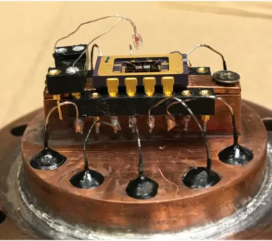
24 Experimental methods bonder (Fig. 2.2 (e) and Fig. 2.3).
2.2 Experimental setup
Figure 2.3: Photograph of a microchannel device mounted in a copper cell.
Each microchannel device was mounted horizontally in a vacuum-tight copper cell, see Fig. 2.3. A tungsten filament placed above the device at the distance about 5 mm served as the electron source for charging the liquid
4He surface in all microchannels.
The vacuum-tight copper cell was filled with liquid
4He and the level of bulk liquid
4He inside the cell was maintained to be slightly lower than the level of the microchannel device (about 1 mm). All the microchannels, therefore, are filled with the liquid
4He by capillary action. The suspended helium surface in the microchannel will curve due to the Van der Waals attraction of liquid to the walls of the microchannel. The radius of curvature R
cof the liquid surface depends on the height of the device above the bulk helium level h, as shown in Fig. 2.4 [42]. For the channel of 10-µm width, the depth of the liquid
4He meniscus ζ
0is expected to be smaller than 50 nm. If the suspended helium film is charged, the electron pressure will result in the decrease of R
c= α/
ρgh +
2n2ee20He
, where α is the surface tension of liquid helium, and g is the
acceleration due to gravity [43]. For n
e≈ 10
13m
−2, we have ζ
ne≈ 240 nm. For a sample
of 5-µm channel width, ζ
0≈ 12 nm and ζ
ne≈ 60 nm. In the experiments described in
the following chapters, we use device with the width of microchannel in the range from
5 to 10 µm, and channel depth in the range from 0.55 to 1.6 µm. The reduction of
liquid helium thickness for such microchannels is approximately 10 % of the physical
channel height for electron density n
e∼ 10
13m
−2for such microchannels. Therefore,
for the sake of simplicity the liquid helium height in the channel is assumed to be the
geometrical height of channel. This simplification mainly affects the estimation of n
efrom the parallel-plate capacitor approximation.
2.2 Experimental setup 25
Figure 2.4: Schematic sketch of the suspended helium film in a corrugated surface. Figure is reproduced from [42].
It is convenient to use a simplified capacitance model to find a relation between the density of electrons in the microchannel and voltages applied to different electrodes of the device [37]. First, we define the total capacitance of the liquid surface in the central microchannel C
Σ= C
bottom+ C
top, where C
bottomand C
topare capacitances between the liquid surface and channel’s bottom and top electrodes, respectively (see Fig. 2.5)).
It is also convenient to introduce the dimensionless coupling constants α = C
top/C
Σand β = C
bottom/C
Σ, which satisfy the obvious relation α + β = 1. Then, the potential at the uncharged liquid surface can be written as V
s= αV
top+ βV
bottom. When the device is charged with electrons, the potential of the charged liquid surface V
ehas to be the same everywhere, owing to high mobility of the surface electrons on liquid helium.
The value of V
eis determined by voltages applied to the reservoir’s bottom and guard electrodes and amount of electrons in the reservoir, and is assumed to be fixed once the device is charged
i. Then, by the definition of capacitance we can write for the total charge Q of electrons in the channel Q = C
Σ(V
e− V
s). A further simplification can be made by assuming a uniform density distribution of electrons in the channel, that is Q = −en
eS, where n
eis the areal density of surface electrons, e > 0 is the electron charge, and S is the channel area. Such a parallel-plate capacitance approximation is partially justified by a large aspect ratio (∼ 10) of a wide and shallow microchannel used in our device. Using C
bottom=
0S/d, where d is the height of the microchannel in our device, we obtain required relation
n
e=
0βed (αV
top+ βV
bottom− V
e) =
0βed (V
s− V
e) . (2.1) In addition to the simplified capacitance model mentioned above, the electron den- sity n
ecan be calculated by numerically solving the Poisson equation with the aid of finite-element model (FEM). We define an electrostatic model of our channel, where the SSE system is represented by an equipotential plane along the helium surface at
i


![Figure 2.4: Schematic sketch of the suspended helium film in a corrugated surface. Figure is reproduced from [42].](https://thumb-ap.123doks.com/thumbv2/123deta/6957877.2273234/44.892.175.725.172.414/figure-schematic-sketch-suspended-corrugated-surface-figure-reproduced.webp)